EP0147843B1 - Awning - Google Patents
Awning Download PDFInfo
- Publication number
- EP0147843B1 EP0147843B1 EP84116295A EP84116295A EP0147843B1 EP 0147843 B1 EP0147843 B1 EP 0147843B1 EP 84116295 A EP84116295 A EP 84116295A EP 84116295 A EP84116295 A EP 84116295A EP 0147843 B1 EP0147843 B1 EP 0147843B1
- Authority
- EP
- European Patent Office
- Prior art keywords
- strips
- awning
- cloth shaft
- another
- shaft
- Prior art date
- Legal status (The legal status is an assumption and is not a legal conclusion. Google has not performed a legal analysis and makes no representation as to the accuracy of the status listed.)
- Expired
Links
Images


Classifications
-
- E—FIXED CONSTRUCTIONS
- E04—BUILDING
- E04F—FINISHING WORK ON BUILDINGS, e.g. STAIRS, FLOORS
- E04F10/00—Sunshades, e.g. Florentine blinds or jalousies; Outside screens; Awnings or baldachins
- E04F10/02—Sunshades, e.g. Florentine blinds or jalousies; Outside screens; Awnings or baldachins of flexible canopy materials, e.g. canvas ; Baldachins
- E04F10/06—Sunshades, e.g. Florentine blinds or jalousies; Outside screens; Awnings or baldachins of flexible canopy materials, e.g. canvas ; Baldachins comprising a roller-blind with means for holding the end away from a building
- E04F10/0633—Arrangements for fastening the flexible canopy material to the supporting structure
-
- E—FIXED CONSTRUCTIONS
- E04—BUILDING
- E04F—FINISHING WORK ON BUILDINGS, e.g. STAIRS, FLOORS
- E04F10/00—Sunshades, e.g. Florentine blinds or jalousies; Outside screens; Awnings or baldachins
- E04F10/02—Sunshades, e.g. Florentine blinds or jalousies; Outside screens; Awnings or baldachins of flexible canopy materials, e.g. canvas ; Baldachins
- E04F10/06—Sunshades, e.g. Florentine blinds or jalousies; Outside screens; Awnings or baldachins of flexible canopy materials, e.g. canvas ; Baldachins comprising a roller-blind with means for holding the end away from a building
- E04F10/0685—Covers or housings for the rolled-up blind
-
- Y—GENERAL TAGGING OF NEW TECHNOLOGICAL DEVELOPMENTS; GENERAL TAGGING OF CROSS-SECTIONAL TECHNOLOGIES SPANNING OVER SEVERAL SECTIONS OF THE IPC; TECHNICAL SUBJECTS COVERED BY FORMER USPC CROSS-REFERENCE ART COLLECTIONS [XRACs] AND DIGESTS
- Y10—TECHNICAL SUBJECTS COVERED BY FORMER USPC
- Y10S—TECHNICAL SUBJECTS COVERED BY FORMER USPC CROSS-REFERENCE ART COLLECTIONS [XRACs] AND DIGESTS
- Y10S160/00—Flexible or portable closure, partition, or panel
- Y10S160/90—Vertical type venetian blind
Definitions
- the invention relates to an awning according to the preamble of claim 1 as z. B. is disclosed in US-A-1 622 245.
- z. B. the awning shown in US-A-2 060 582 has the disadvantage that two separate fabric shafts are required, which complicates the construction considerably; and that the two strips of cloth are connected to one another by a zipper, whereby a relatively large area of the cloth is exposed to the wind; this in turn requires a particularly strong training of the frame.
- CH-A-274 744 shows a sun blind in which the transverse covering strips are fastened at a distance from one another over part of their width on two fabric belts that can be rolled up on the fabric shaft, while the part of the strips pointing outwards hangs freely downwards.
- Such a construction is relatively complicated, offers problems with the hanging strips both when rolling and when unrolling, and was therefore not able to assert itself.
- the covering usually runs between two supporting parts, namely a drop profile, which is attached to articulated arms, drop arms or the like, and a cloth shaft, on which it can be rolled up.
- a drop profile which is attached to articulated arms, drop arms or the like
- a cloth shaft on which it can be rolled up.
- the covering In the unrolled state, the covering is exposed to the wind pressure, which not only requires a high tensile strength of the covering, but also a massive and consequently seeming cumbersome structural design of the frame, in particular the articulated arms or similar display means, which is also reflected in high manufacturing costs.
- the invention has now set itself the task of creating an awning that can withstand stronger wind gusts despite relatively light construction and avoids the disadvantages of known awnings mentioned. This is achieved according to the invention by the features described in the characterizing part of claim 1.
- US-A-591 918 was also recognized, but with its strips composed of individual lobes it already belongs to another genus, since it does not pose the problem of wind pressure. Moreover, the individual battens would be too stiff to bulge under wind pressure if they did not let air through between them.
- a cover designed in this way hardly differs visually from the cover formed in one piece in the unclamped or extended state.
- the slits between the strips open more or less and allow the moving air to pass through for the most part, so that the remaining air congestion that presses on the strips is very low.
- the clothing which is thus loaded much less, can therefore be made lighter, which also applies to the frame or the exhibition means.
- This also makes constructions that appear easy to look at possible, which due to their small dimensions can still be installed in confined spaces, which reduces the manufacturing costs. If the fabric is damaged, only the damaged strips have to be replaced.
- the storage of clothing of different sizes and color combinations is cumbersome and time-consuming.
- the strip shape now offers the possibility of assembling the required covering width from individual strips - possibly even of different widths.
- the choice of colors and their sequence can be varied according to the wishes of the customers.
- Fig. 1 shows schematically a roller blind or awning 11, the covering 17 is fixed on one end to the fabric shaft 13 and the other on a drop profile 16.
- the cloth shaft 13 is rotatably mounted and actuated in a known manner on (not shown) support elements.
- Articulated arms 14 which carry the drop profile 16 are articulated on pivot bearings 15.
- the strips 18 can be the same width or, as in the example, have different widths.
- the strips 18 run in the rolling direction. In the idle state, the longitudinal edges 10 of two adjacent strips touch each other.
- the strips 18 can be arranged so closely next to one another in one plane, that the longitudinal edges 10 are closed.
- Each strip 18, 18 ' is preferably fastened in the center of the drop profile 16, so that the longitudinal edges 10 of the strips 18' can bulge from below with the formation of slots 30 when the wind is loaded.
- the attachment can also be carried out on the longitudinal edge of each strip facing the main wind direction; However, it is more stable to fasten it to at least two points on the front ends of the strips by means of a strip, a clamping profile or the like.
- Holes 20 are provided in the drop profile 16 for the fastening of the fabric strips 18 'at intervals corresponding to the strip widths, which holes can be provided in a known manner with retaining springs 22 for holding a push button 21 each on the strips 18, 18'.
- any other construction of such a quick fastener is possible. In the case of large winds, however, such a resilient attachment may not be secure enough, so that a connection that cannot be released in the locked state is more appropriate.
- the thickened end of the push button 21 can also be inserted into the wide end of a keyhole opening, which is arranged in a slider on the drop profile 16, whereupon the slider is moved so that the narrower part of the keyhole opening the neck of the push button 21 below the grips thickened end and so holds.
- the longitudinal edges of the strips 18 can be opened with devices that open under pressure, such as, for. B. a plurality of interlocking, elastic barbs, zipper-like connectable or releasable form-fitting connections or the like.
- the edge of the fabric strips 18 can also be provided, for example, with a bristle strip 23, the bristles of adjacent fabric strips 18 interlocking, opposing the opening of the slots with a certain resistance and in this way avoiding fluttering in low winds.
- the strips 18 ' can also be connected to one another between the longitudinal edges of mutually adjacent strips of fabric by a connecting seam with elastically stretchable threads 24, in particular made of elastic polyurethane plastic, which likewise gives a certain counterforce against opening of the slots 30.
- elastically stretchable threads 24 in particular made of elastic polyurethane plastic, which likewise gives a certain counterforce against opening of the slots 30.
- plastic is recommended because natural rubber ages too quickly when exposed to sunlight. If the closing force that can be achieved by a seam extending over the entire length of the strip is too great, it is also possible to carry out the seam only intermittently, ie with interruptions.
- This problem can e.g. 7 can be solved in that the longitudinal edges of the strips 18 are held under tension in relation to their central zones in that the hemstitch 48 intended for the insertion of the clamping bars or inserts 40 is made convex, so that in the extended, tensioned state . the peripheral zones are somewhat shorter than the central zones.
- the strips 18 can also be stabilized transversely to the rolling or tensioning direction. This can e.g. B. by transverse reinforcing inserts or by using stretch-free textile material, such as glass fiber, happen, whereby the shrinkage of the strips in the transverse direction - in the longitudinal direction - can be prevented or at least kept small.
- Very rigid transverse threads can also be used in relation to the longitudinal threads in order to improve the transverse stability.
- the longitudinal edges can be reinforced with tensile strength or more elastic than the central zone.
- the reinforcement of the longitudinal edges can be done by the formation of hems, a thicker selvedge, the application of tensile edge bands or the like, but this has the disadvantage that the covering roll is fixed when rolling through the thicker edge zones and the middle zones sag. Again, this can lead to delays.
- a reinforcement of the Longitudinal edges without increasing the thickness achieved by sewing the edge seam with a slight pretension (e.g. crimp crepe with elastic thread) in a zigzag; or the edge warp threads are selected from more or less elastic material during the manufacture of the fabric strips.
- Another advantage of the slat concept is that certain warps or folds are usually very difficult to avoid both when sewing and when delivering the folded awning fabrics. Slats do not necessarily have to be sewn lengthways, but are delivered rolled. This solved two problems in one fell swoop. Even in the case of very wide awnings, a fabric shaft support has been installed to prevent sagging, which means that dust and dirt are rubbed into the fabric and that there are traces of grinding that can no longer be removed, so that the entire covering must be replaced . With the striped covering, a damaged or soiled strip can easily be replaced.
Abstract
Description
Die Erfindung betrifft eine Markise nach dem Oberbegriff des Anspruches 1, wie sie z. B. in der US-A-1 622 245 geoffenbart ist. Weiters weist z. B. die in der US-A-2 060 582 gezeigte Markise den Nachteil auf, dass zwei getrennte Tuchwellen erforderlich sind, was die Konstruktion beträchtlich kompliziert ; und dass die beiden Tuchstreifen durch einen Zippverschluss miteinander verbunden sind, wodurch eine relativ grosse Tuchfläche dem Wind ausgesetzt ist ; dies erfordert wiederum eine besonders starke Ausbildung des Gestells. Weiters zeigt die CH-A-274 744 einen Sonnenstoren, bei dem an zwei auf der Tuchwelle aufrollbaren Stoffgurten die querverlaufenden Bespannungsstreifen über einen Teil ihrer Breite im Abstand voneinander befestigt sind, während der nach aussen weisende Teil der Streifen frei nach unten hängt. Eine solche Konstruktion ist verhältnismässig kompliziert, bietet sowohl beim Aufwie beim Abrollen Probleme mit den herabhängenden Streifen und konnte sich daher nicht durchsetzen.The invention relates to an awning according to the preamble of claim 1 as z. B. is disclosed in US-A-1 622 245. Furthermore, z. B. the awning shown in US-A-2 060 582 has the disadvantage that two separate fabric shafts are required, which complicates the construction considerably; and that the two strips of cloth are connected to one another by a zipper, whereby a relatively large area of the cloth is exposed to the wind; this in turn requires a particularly strong training of the frame. Furthermore, CH-A-274 744 shows a sun blind in which the transverse covering strips are fastened at a distance from one another over part of their width on two fabric belts that can be rolled up on the fabric shaft, while the part of the strips pointing outwards hangs freely downwards. Such a construction is relatively complicated, offers problems with the hanging strips both when rolling and when unrolling, and was therefore not able to assert itself.
Die Bespannung verläuft in aller Regel zwischen zwei Tragteilen, nämlich einem Ausfallprofil, das an Gelenkarmen, Fallarmen oder dergleichen befestigt ist, und einer Tuchwelle, auf der sie aufrollbar ist. Im abgerollten Zustand ist die Bespannung dem Winddruck ausgesetzt, der nicht nur eine hohe Reissfestigkeit der Bespannung, sondern auch eine massive und mithin schwerfällig erscheinende konstruktive Ausbildung des Gestells, insbesondere der Gelenkarme oder dergleichen Ausstellmittel verlangt, was sich auch in hohen Herstellungskosten niederschlägt.The covering usually runs between two supporting parts, namely a drop profile, which is attached to articulated arms, drop arms or the like, and a cloth shaft, on which it can be rolled up. In the unrolled state, the covering is exposed to the wind pressure, which not only requires a high tensile strength of the covering, but also a massive and consequently seeming cumbersome structural design of the frame, in particular the articulated arms or similar display means, which is also reflected in high manufacturing costs.
Man hat daher auch schon die Aufteilung einer grösseren Bespannungsfläche in mehrere kleinere Einzelmarkisen vorgeschlagen, z. B. in der FR-A-829 881 für eine um eine Gebäudeecke reichende Markise, doch ist eine solche Konstruktion wegen der Notwendigkeit einer Mehrzahl von Tuchwellen mit eigenem Antrieb und Ausstellmitteln ausserordentlich aufwendig.It has therefore already been proposed to divide a larger covering area into several smaller individual awnings, e.g. B. in FR-A-829 881 for an awning extending around a building corner, but such a construction is extremely complex because of the need for a plurality of fabric shafts with its own drive and exhibiting means.
Die Erfindung hat sich nun zur Aufgabe gestellt, eine Markise zu schaffen, die trotz verhältnismässig leichter Konstruktion auch stärkeren Windböen standhalten kann und die erwähnten Nachteile bekannter Markisen vermeidet. Dies gelingt erfindungsgemäss durch die im kennzeichnenden Teil des Anspruches 1 beschriebenen Merkmale. Dem gegenüber wurde auch die US-A-591 918 gewürdigt, die aber mit ihren aus einzelnen Lappen zusammengesetzten Streifen bereits einer anderen Gattung angehört, da sich bei ihr das Problem des Winddrucks gar nicht stellt. Ueberdies würden die einzelnen Latten zu steif sein, um sich unter Winddruck aufzuwölben, wenn sie nicht zwischen einander Luft durchliessen.The invention has now set itself the task of creating an awning that can withstand stronger wind gusts despite relatively light construction and avoids the disadvantages of known awnings mentioned. This is achieved according to the invention by the features described in the characterizing part of claim 1. On the other hand, US-A-591 918 was also recognized, but with its strips composed of individual lobes it already belongs to another genus, since it does not pose the problem of wind pressure. Moreover, the individual battens would be too stiff to bulge under wind pressure if they did not let air through between them.
Eine derart ausgebildete Bespannung unterscheidet sich im ausgespannten bzw. ausgefahrenen Zustand optisch kaum von den einstückig ausgebildeten Bespannungen. Bei Windangriff öffnen sich die Schlitze zwischen den Streifen mehr oder weniger weit und lassen die bewegte Luft grossteils passieren, so dass der noch verbleibende, auf die Streifen drückende Luftstau sehr gering ist. Die somit erheblich geringer belastete Bespannung kann daher leichter ausgeführt sein, was auch für das Gestell bzw. die Ausstellmittel zutrifft. Dadurch werden auch optisch leicht erscheinende Konstruktionen möglich, die infolge ihrer geringen Dimensionierung noch an beengten Stellen montierbar sind, wodurch sich die Herstellkosten vermindern. Bei einer Beschädigung der Bespannung sind lediglich die beschädigten Streifen zu ersetzen.A cover designed in this way hardly differs visually from the cover formed in one piece in the unclamped or extended state. In the event of a wind attack, the slits between the strips open more or less and allow the moving air to pass through for the most part, so that the remaining air congestion that presses on the strips is very low. The clothing, which is thus loaded much less, can therefore be made lighter, which also applies to the frame or the exhibition means. This also makes constructions that appear easy to look at possible, which due to their small dimensions can still be installed in confined spaces, which reduces the manufacturing costs. If the fabric is damaged, only the damaged strips have to be replaced.
Die Lagerhaltung von Bespannungen verschiedener Grösse und Farbzusammenstellungen ist umständlich und aufwendig. Die Streifenform bietet nun die Möglichkeit, die jeweils erforderliche Bespannungsbreite aus - gegebenenfalls sogar verschieden breiten - Einzelstreifen zusammenzustellen. Zudem kann die Farbenwahl und deren Folge den Wünschen der Kunden entsprechend variiert werden.The storage of clothing of different sizes and color combinations is cumbersome and time-consuming. The strip shape now offers the possibility of assembling the required covering width from individual strips - possibly even of different widths. In addition, the choice of colors and their sequence can be varied according to the wishes of the customers.
Vorteilhafte Verbesserungen und weitere Ausbildungen werden, wie in den Unteransprüche erwähnt, vorgeschlagen. Den Zeichnungen sind Ausführungsbeispiele der Erfindung in schematischen Darstellungen zu entnehmen. Es zeigen
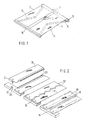
- Fig. 1 eine Markise mit ab- bzw. aufrollbarer Bespannung in einer perspektivischen Darstellung,
- Fig. 2 verschiedene Verbindungsmöglichkeiten zwischen den Längsrändern der Streifen und eine Befestigung der Streifen am Ausfallprofil in perspektivischer Darstellung,
- Fig. 3 einen schematischen Querschnitt durch eine Markise,
- Fig. 4a und 4b Querschnitte eines Markisenausschnittes am tuchwellenseitigen Ende der Streifen.
- Fig. 5 eine Doppelmarkise im Querschnitt und
- Fig. 6 eine Bespannung in der Draufsicht,
- Fig. 7 den Endbereich eines Streifens in der Draufsicht.
- 1 an awning with a roll-up or roll-up covering in a perspective view,
- 2 different connection options between the longitudinal edges of the strips and an attachment of the strips to the drop profile in a perspective view,
- 3 shows a schematic cross section through an awning,
- 4a and 4b cross sections of an awning cutout at the cloth shaft end of the strips.
- Fig. 5 is a double awning in cross section and
- 6 a covering in a top view,
- Fig. 7 shows the end region of a strip in a top view.
Fig. 1 zeigt schematisch eine Rollblende bzw. Markise 11, deren Bespannung 17 einerends an der Tuchwelle 13 und anderends an einem Ausfallprofil 16 befestigt ist. Die Tuchwelle 13 ist in bekannter Weise an (nicht dargestellten) Tragelementen drehbar gelagert und betätigbar. An Schwenklagern 15 sind Gelenkarme 14 angelenkt, die das Ausfallprofil 16 tragen.Fig. 1 shows schematically a roller blind or awning 11, the covering 17 is fixed on one end to the
Die mithin einerseits vom Ausfallprofil 16 und andererseits von der Tuchwelle 13 getragene Bespannung 17 aus flexiblem Textilmaterial ist in Streifen 18 aufgeteilt. Die Streifen 18 können gleich breit sein oder, wie im Beispiel, unterschiedliche Breiten haben. Die Streifen 18 verlaufen in Abrollrichtung. Im Ruhezustand berühren einander die Längsränder 10 zweier benachbarter Streifen.The covering 17 made of flexible textile material, which is carried on the one hand by the
Auch nach Fig. 2 können die Streifen 18 in einer Ebene so dicht nebeneinander angeordnet sein, dass die Längsränder 10 geschlossen.sind. Jeder Streifen 18, 18' ist am Ausfallprofil 16 vorzugsweise mittig befestigt, so dass sich die Längskanten 10 der Streifen 18' bei Windbelastung von unten unter Ausbildung von Schlitzen 30 aufwölben können. Die Befestigung kann auch auf dem der Hauptwindrichtung zugekehrten Längsrand jedes Streifens erfolgen ; stabiler ist jedoch eine Befestigung an wenigstens zwei Stellen der Stirnenden der Streifen mittels einer Leiste, eines Klemmprofils oder dergleichen.2, the
Für die Befestigung der Stoffstreifen 18' sind im Ausfallprofil 16 in - den Streifenbreiten entsprechenden Abständen - Löcher 20 vorgesehen, die zum Festhalten je eines Druckknopfes 21 an den Streifen 18, 18' in bekannter Weise mit Haltefedern 22 versehen sein können. Selbstverständlich ist jede andere Konstruktion eines solchen Schnellverschlusses möglich. Bei grossen Windstärken ist jedoch eine derartig federnde Befestigung gegebenenfalls nicht sicher genug, so dass eine im Verriegelungszustand unlösbare Verbindung zweckmässiger ist. Zu diesem Zweck kann das verdickte Ende des Druckknopfs 21 zusätzlich in das breite Ende einer Schlüssellochöffnung eingeführt werden, die in einem Schieber am Ausfallprofil 16 angeordnet ist, worauf der Schieber so verschoben wird, dass der schmälere Teil der Schlüssellochöffnung den Hals des Druckknopfs 21 unterhalb des verdickten Endes umgreift und so festhält.
Um auch bei sehr geringer Steifheit der Streifen 18 schon bei geringem Luftzug ein Flattern zu vermeiden, können die Längsränder der Streifen 18 mit unter Druckbelastung sich öffnenden Einrichtungen, wie z. B. einer Vielzahl ineinander greifender, elastischer Widerhäkchen, reissverschlussartig verbind- bzw. lösbarer Formschlussverbindungen oder dergleichen versehen sein.In order to avoid fluttering even with a slight draft, even with very low stiffness of the
Auch kann der Rand der Stoffstreifen 18 beispielsweise mit einem Borstenstreifen 23 versehen sein, wobei die Borsten einander benachbarter Stoffstreifen 18 ineinandergreifen, dem Oeffnen der Schlitze einen gewissen Widerstand entgegensetzen und auf diese Weise ein Flattern bei geringer Windstärke vermeiden.The edge of the
Die Streifen 18' können auch zwischen den Längsrändern einander benachbarter Stoffstreifen durch jeweils eine Verbindungsnaht mit elastisch dehnbaren Fäden 24, insbesondere aus elastischem Polyurethan-Kunststoff, miteinander verbunden sein, die ebenfalls eine bestimmte Gegenkraft gegen ein Oeffnen der Schlitze 30 ergibt. Die Verwendung von Kunststoff empfiehlt sich deshalb, weil Naturgummi bei Sonnenbestrahlung allzu schnell altert. Falls die von einer über die ganze Streifenlänge reichenden Naht erzielbare Schliesskraft zu gross sein sollte, ist es auch möglich, die Naht nur absatzweise, also mit Unterbrechungen auszuführen.The strips 18 'can also be connected to one another between the longitudinal edges of mutually adjacent strips of fabric by a connecting seam with elastically
An den Enden über die Breite der Streifen 18 verlaufende Nähte können zur Befestigung der Bespannung am Ausfallprofil 16 dienen, wobei allerdings auch eine im wesentlichen punktförmige Verankerung mittels Gummifäden möglich ist. Durch solch eine elastische Verankerung können die Streifen 18 besonders weit voneinander abheben, so dass eine ausgezeichnete Luftdurchlässigkeit der Bespannung erzielbar ist. Andererseits bietet die Verankerung mittels des Schnellverschlusses 20-22 bestimmte Vorteile bei der individuellen Zusammenstellung von Bespannungen, die so rasch zu der gewünschten Breite und Farbmusterung leicht ausgetauscht werden können.Seams at the ends across the width of the
Gemäss Fig. 3 können die in Abrollrichtung verlaufenden Streifen 418, 518 an der Tuchwelle 113 mit ihren Enden in zwei Nuten 36, 37 verlaufen, die entlang des Tuchwellenmantels in Umfangsrichtung versetzt angeordnet und mit Hilfe von Klemmstäben bzw. Einsatzstücken 40, 41 befestigt sind. Entsprechend sind die anderen Enden der Streifen 418, 518 in zwei im Ausfallprofil 416 nebeneinander verlaufenden Nuten 38, 39 mit Hilfe von Klemmstäben bzw. Einsatzstücken 42, 43 befestigt. Der Abstand der paarweise angeordneten Nuten 36, 37 und 38, 39 voneinander ist zweckmässig so klein gewählt, dass die Streifen 418, 51Bim ausgefahrenen Zustand dicht übereinander liegen.According to FIG. 3, the
Normale Stoffstreifen würden zwar auf der Tuchwelle und dem Ausfallprofil satt nebeneinander liegen, in der Mitte aber klaffen, was bei einer Streifenbreite von 200 mm und einer ausgefahrenen Länge von 300 cm bei üblichen Markisenstoffen Schlitze 30 von 1-3 cm ergibt. Dadurch fallen störende Licht- bzw. Sonnenstreifen durch die Bespannung, die unschön aussieht, wie aus Fig. 6 ersichtlich ist.Normal strips of fabric would lie snugly next to each other on the fabric shaft and the drop profile, but would gap in the middle, which, with a strip width of 200 mm and an extended length of 300 cm, would result in
Dieses Problem kann z. B. gemäss Fig. 7 dadurch gelöst werden, dass die Längsränder der Streifen 18 gegenüber ihren Mittelzonen dadurch unter Zugspannung gehalten werden, dass der für den Einschub der Klemmstäbe bzw. Einsatzstücke 40 bestimmte Hohlsaum 48 konvex ausgebildet wird, so dass im ausgefahrenen, gespannten Zustand. die Randzonen etwas kürzer sind als die Mittelzonen. Es können aber auch die Streifen 18 quer zur Roll- oder Spannrichtung stabilisiert werden. Dies kann z. B. durch quer verlaufende Versteifungseinlagen oder durch die Vewendung dehnungsfreien Textilmaterials, beispielsweise Glasfasergewebe, geschehen, wodurch der Schrumpf der Streifen in Querrichtung - bei Zugbeanspruchung in Längsrichtung - verhindert oder zumindest klein gehalten werden kann. Es können auch im Verhältnis zu den Längsfäden sehr steife Querfäden verwendet werden, um die Querstabilität zu verbessern.This problem can e.g. 7 can be solved in that the longitudinal edges of the
Die Längsränder können zugfest verstärkt oder elastischer als die Mittelzone ausgebildet werden. Die Verstärkung der Längsränder kann durch die Ausbildung von Säumen, eine dickere Webkante, das Aufbringen von zugfesten Randbändern oder dergleichen geschehen, was aber den Nachteil hat, dass der Bespannungswickel beim Aufrollen durch die dickeren Randzonen festgelegt ist und die Mittelzonen durchhängen. Dies kann im Lauf der Zeit wiederum zu Verzugserscheinungen führen. Zweckmässig wird eine Verstärkung der Längsränder ohne Dickenzuwachs dadurch erzielt, dass die Randnaht mit leichter Vorspannung (z. B. Kräuselkrepp mit elastischem Faden) eventuell im Zick-Zack genäht wird ; oder es werden bereits bei der Herstellung der Stoffstreifen die Randkettfäden aus mehr oder weniger elastischem Material gewählt.The longitudinal edges can be reinforced with tensile strength or more elastic than the central zone. The reinforcement of the longitudinal edges can be done by the formation of hems, a thicker selvedge, the application of tensile edge bands or the like, but this has the disadvantage that the covering roll is fixed when rolling through the thicker edge zones and the middle zones sag. Again, this can lead to delays. A reinforcement of the Longitudinal edges without increasing the thickness achieved by sewing the edge seam with a slight pretension (e.g. crimp crepe with elastic thread) in a zigzag; or the edge warp threads are selected from more or less elastic material during the manufacture of the fabric strips.
Mit Hilfe des gemäss Fig. 3 gezeigten Prinzips ist auch eine Doppelmarkise nach Fig. 5 möglich, wie sie als Ständermarkise, zur Abdeckung von Glashäusern oder dergleichen zum Einsatz kommt. Die beiden Bespannungen bilden Streifen 418, 518 und werden auf einer Tuchwelle 113 auf- bzw. abgerollt. Ihr anderes Ende ist an je einem Ausfallprofil 516 und 516' befestigt.With the aid of the principle shown in FIG. 3, a double awning according to FIG. 5 is also possible, such as that used as a stand awning, for covering glass houses or the like. The two coverings form strips 418, 518 and are rolled up or rolled off on a
Die Streifen 418 können alternativ auch über eine Umlenkrolle 44 über eine Ebene 418" geführt werden, die dann dieselbe Neigung wie diejenige der Streifen 518 haben kann.The
Die Erfindung ist nicht auf die dargestellten Ausführungsformen beschränkt. So kann die Tuchwelle beispielsweise mit vier Nuten versehen sein.The invention is not restricted to the illustrated embodiments. For example, the fabric shaft can be provided with four grooves.
Ein weiterer Vorteil des Lamellenkonzepts liegt aber auch darin, dass sowohl beim Nähen als auch beim Liefern der zusammengefalteten Markisenstoffe gewisse Verwerfungen oder Faltenbildungen meist nur sehr schwer zu vermeiden sind. Lamellen müssen aber in der Längsrichtung nicht unbedingt genäht werden, sondern werden gerollt geliefert. Damit hat man zwei Probleme mit einem Schlag gelöst. Auch bei sehr breiten Markisen wird zur Vermeidung des Durchhängens bisher eine Tuchwellenstütze eingebaut, die zur Folge hat, dass Staub und Schmutz in den Stoff eingerieben werden und dass es Schleifspuren gibt, die nicht mehr zu beseitigen sind, so dass die gesamte Bespannung ausgewechselt werden muss. Bei der streifenförmigen Bespannung kann einfach ein beschädigter oder beschmutzter Streifen problemlos ausgewechselt werden.Another advantage of the slat concept is that certain warps or folds are usually very difficult to avoid both when sewing and when delivering the folded awning fabrics. Slats do not necessarily have to be sewn lengthways, but are delivered rolled. This solved two problems in one fell swoop. Even in the case of very wide awnings, a fabric shaft support has been installed to prevent sagging, which means that dust and dirt are rubbed into the fabric and that there are traces of grinding that can no longer be removed, so that the entire covering must be replaced . With the striped covering, a damaged or soiled strip can easily be replaced.
Bei dem Beispiel nach Fig. 4a und 4b befinden sich in der hier längs geschlitzten hohlen Tuchwelle 213 in einem der Breite der Streifen 18 entsprechenden axialen Abstand Schnekkengetriebe 47, mit denen die Streifenenden jeweils mittig in Art einer Jalousie mit lotrechten Lamellen verbunden sind. In der geschlossenen Lage liegen die Streifen 18 in einer durch die Tuchwellenachse gehenden Ebene. In der in Fig. 4a gezeigten Position sind die Streifen 18 gegenüber der Tuchwelle 213 mit Hilfe der Schneckengetriebe 47 um 90 Grad verdreht worden, so dass zum Beispiel Wind in Richtung parallel zur Zeichenebene durchstreichen kann. In Fig. 4b schliesslich ist gezeigt, wie die Streifen 18, die andernends am Ausfallprofil 16 betestigt sind, auf die die Schneckengetriebe 47 enthaltende Tuchwelle 213 aufgerollt werden können. Die Betätigung der Schneckengetriebe erfolgt in allgemein bekannter Weise.In the example according to FIGS. 4a and 4b there are
Claims (7)
Priority Applications (1)
| Application Number | Priority Date | Filing Date | Title |
|---|---|---|---|
| AT84116295T ATE37579T1 (en) | 1983-12-30 | 1984-12-24 | AWNING. |
Applications Claiming Priority (2)
| Application Number | Priority Date | Filing Date | Title |
|---|---|---|---|
| CH699383 | 1983-12-30 | ||
| CH6993/83 | 1983-12-30 |
Publications (3)
| Publication Number | Publication Date |
|---|---|
| EP0147843A2 EP0147843A2 (en) | 1985-07-10 |
| EP0147843A3 EP0147843A3 (en) | 1985-08-14 |
| EP0147843B1 true EP0147843B1 (en) | 1988-09-28 |
Family
ID=4318252
Family Applications (1)
| Application Number | Title | Priority Date | Filing Date |
|---|---|---|---|
| EP84116295A Expired EP0147843B1 (en) | 1983-12-30 | 1984-12-24 | Awning |
Country Status (5)
| Country | Link |
|---|---|
| US (1) | US4794971A (en) |
| EP (1) | EP0147843B1 (en) |
| JP (1) | JPS60156856A (en) |
| AT (1) | ATE37579T1 (en) |
| DE (2) | DE3400242C1 (en) |
Families Citing this family (16)
| Publication number | Priority date | Publication date | Assignee | Title |
|---|---|---|---|---|
| JPH01118029U (en) * | 1988-01-29 | 1989-08-09 | ||
| JPH01148431U (en) * | 1988-03-18 | 1989-10-13 | ||
| EP0351459A1 (en) * | 1988-07-18 | 1990-01-24 | Masayoshi Fukushi | Sub-awning sheet support assembly |
| US5450890A (en) * | 1993-10-01 | 1995-09-19 | Rite-Hite Corporation | Roll-up strip curtain barrier apparatus |
| US5542463A (en) * | 1993-10-01 | 1996-08-06 | Rite-Hite Corporation | Roll-up strip curtain barrier apparatus |
| FR2842244B1 (en) * | 2002-07-11 | 2005-04-29 | Tavernier Serge De | PROTECTIVE DEVICE AGAINST SOLAR RADIATION |
| DE102005030973A1 (en) † | 2005-06-30 | 2007-01-11 | Webasto Ag | Roller blind arrangement for a motor vehicle |
| KR100864223B1 (en) | 2007-06-04 | 2008-10-17 | 김만수 | Sunscreen having up and down vent hole |
| US7784480B2 (en) * | 2007-09-13 | 2010-08-31 | Bravo Sports | Canopy with ventilation |
| US7798162B2 (en) * | 2007-09-13 | 2010-09-21 | Bravo Sports | Canopy with reinforced eaves |
| US7753064B2 (en) * | 2007-09-13 | 2010-07-13 | Bravo Sports Corporation | Canopy latch system |
| US7775229B2 (en) * | 2008-08-29 | 2010-08-17 | Bravo Sports | Canopy with one or more side awnings |
| US20120102707A1 (en) * | 2010-11-02 | 2012-05-03 | Chicology, Inc. | Method for manufacturing shade of a blind |
| US20120103539A1 (en) * | 2010-11-02 | 2012-05-03 | Chicology, Inc. | Shade Structure |
| US20140345811A1 (en) * | 2013-05-21 | 2014-11-27 | Gary McDaniel | Garage door opening covering |
| US9850663B1 (en) * | 2014-05-05 | 2017-12-26 | Carefree/Scott Fetzer Company | Awning canopy cover and connection system |
Citations (3)
| Publication number | Priority date | Publication date | Assignee | Title |
|---|---|---|---|---|
| US591918A (en) * | 1897-10-19 | 1897-10-19 | friedrich | |
| US1622245A (en) * | 1925-04-27 | 1927-03-22 | Regal Shoe Company | Awning |
| EP0108424A1 (en) * | 1982-11-09 | 1984-05-16 | Abatenda di Serafini Giovanni | Sunshade fitting convertible into veranda curtain fitting |
Family Cites Families (40)
| Publication number | Priority date | Publication date | Assignee | Title |
|---|---|---|---|---|
| US26965A (en) * | 1860-01-31 | Filter | ||
| DE449203C (en) * | 1927-12-19 | Hugo Mueller | Adjustable sun roof for windows, balconies etc. | |
| US1318820A (en) * | 1919-10-14 | Vehicle-canopy | ||
| DE614499C (en) * | 1935-06-11 | Maschf Augsburg Nuernberg Ag | Device for tensioning flag-like lengths of fabric | |
| DE70451C (en) * | TH. DANION in Rennes, Dep. Ille et Vilaine, Frankreich | Roll-up curtain with transverse bees curved in the width direction | ||
| US544371A (en) * | 1895-08-13 | ortmann | ||
| US709913A (en) * | 1902-05-14 | 1902-09-30 | Burton T Lamb | Awning. |
| GB190915519A (en) * | 1909-07-03 | 1910-04-28 | Charles Edwards | Ventilated Roller Blinds. |
| US1573159A (en) * | 1923-05-07 | 1926-02-16 | Louis N Gross | Ventilated sunshade |
| US1557058A (en) * | 1924-11-13 | 1925-10-13 | Knud Murck And Thomas J Gilmou | Shade roller |
| US1649943A (en) * | 1925-11-23 | 1927-11-22 | Boeck Harry | Sun blind |
| US1750271A (en) * | 1927-11-07 | 1930-03-11 | Kasan Louis | Awning |
| US1786048A (en) * | 1928-01-11 | 1930-12-23 | Highway Trailer Co | Flexible cover for dumping bodies |
| US2060582A (en) * | 1933-01-20 | 1936-11-10 | Geo B Carpenter & Co | Awning |
| DE641382C (en) * | 1934-03-30 | 1937-01-29 | Anton V J Godan | Rollable strip curtain |
| US2100976A (en) * | 1936-07-06 | 1937-11-30 | Chester H Norton | Venetian shade |
| FR829881A (en) * | 1936-12-01 | 1938-07-08 | Device for awnings or blinds with pyramidal extension | |
| DE695045C (en) * | 1937-12-14 | 1940-08-14 | Maschf Augsburg Nuernberg Ag | en long length of fabric |
| US2173275A (en) * | 1937-12-31 | 1939-09-19 | Houmere Walter | Fabric venetian blind |
| US2207420A (en) * | 1939-09-20 | 1940-07-09 | Carl M Thomas | Window covering |
| US2314508A (en) * | 1941-08-14 | 1943-03-23 | Ernest J Monteleone | Display device |
| US2384377A (en) * | 1943-08-02 | 1945-09-04 | Frederick W Holstein | Combination sliding and rolling light screen |
| FR905154A (en) * | 1943-09-01 | 1945-11-27 | Balatum Nv | Sun protection blinds |
| US2426133A (en) * | 1945-10-09 | 1947-08-19 | Crown Fastener Corp | Awning structure |
| US2572257A (en) * | 1946-08-27 | 1951-10-23 | Eugene G Gerner | Sheet metal panel |
| CH274744A (en) * | 1949-10-19 | 1951-04-30 | Buetzberger Otto | Openable sun blinds. |
| US2898983A (en) * | 1956-11-30 | 1959-08-11 | Chamberlain Corp | Roll-up awning |
| FR1229964A (en) * | 1959-03-26 | 1960-09-12 | Dewez Sa | Store |
| FR1249000A (en) * | 1960-02-22 | 1960-12-23 | High comfort awning with accelerated ventilation | |
| FR82430E (en) * | 1962-10-10 | 1964-02-07 | Fermetures Mischler | Closing device with parallel slats for all types of windows |
| CH423556A (en) * | 1963-10-30 | 1966-10-31 | Boshoven Hans | Signal device with a passing flag on a barge |
| US3351163A (en) * | 1964-02-27 | 1967-11-07 | Bromsregulator Svenska Ab | Automatic slack adjuster for vehicle brakes |
| FR1480262A (en) * | 1966-03-29 | 1967-05-12 | New Venetian blind | |
| FR2033508A5 (en) * | 1969-02-26 | 1970-12-04 | Burnet Marcel | |
| US3952758A (en) * | 1971-09-03 | 1976-04-27 | Addison Frank F | Canopy |
| GB1404624A (en) * | 1972-10-05 | 1975-09-03 | Polyweld Plastic Co Ltd | Display devices |
| DE2514941C3 (en) * | 1975-04-05 | 1984-06-20 | Clauss Markisen, 7311 Bissingen | awning |
| NZ183871A (en) * | 1976-05-19 | 1980-12-19 | Clopay Corp | Roller blind adjustable width roller and shade |
| IT1081049B (en) * | 1977-08-03 | 1985-05-16 | Ri Ri Italia Spa | ARTICULATED SUPPORT FOR ROLLING SHUTTERS |
| DE2913888C2 (en) * | 1979-04-06 | 1983-01-05 | Hunter Douglas Industries B.V., 3008 Rotterdam | Louvre blinds with vertical slats |
-
1984
- 1984-01-05 DE DE3400242A patent/DE3400242C1/en not_active Expired
- 1984-12-24 DE DE8484116295T patent/DE3474330D1/en not_active Expired
- 1984-12-24 EP EP84116295A patent/EP0147843B1/en not_active Expired
- 1984-12-24 AT AT84116295T patent/ATE37579T1/en active
- 1984-12-25 JP JP59272154A patent/JPS60156856A/en active Pending
-
1987
- 1987-02-06 US US07/011,458 patent/US4794971A/en not_active Expired - Fee Related
Patent Citations (3)
| Publication number | Priority date | Publication date | Assignee | Title |
|---|---|---|---|---|
| US591918A (en) * | 1897-10-19 | 1897-10-19 | friedrich | |
| US1622245A (en) * | 1925-04-27 | 1927-03-22 | Regal Shoe Company | Awning |
| EP0108424A1 (en) * | 1982-11-09 | 1984-05-16 | Abatenda di Serafini Giovanni | Sunshade fitting convertible into veranda curtain fitting |
Also Published As
| Publication number | Publication date |
|---|---|
| EP0147843A3 (en) | 1985-08-14 |
| JPS60156856A (en) | 1985-08-17 |
| EP0147843A2 (en) | 1985-07-10 |
| DE3400242C1 (en) | 1985-03-28 |
| ATE37579T1 (en) | 1988-10-15 |
| US4794971A (en) | 1989-01-03 |
| DE3474330D1 (en) | 1988-11-03 |
Similar Documents
| Publication | Publication Date | Title |
|---|---|---|
| EP0147843B1 (en) | Awning | |
| DE602004011159T2 (en) | Attaching a roller blind curtain | |
| DE69929776T2 (en) | TRANSLUCENT CELLULAR WINDOW SCREEN | |
| DE3525515A1 (en) | Curtain with adjustable visibility protection slats | |
| DE60303097T2 (en) | Cellular structure and method for producing a cellulase structure | |
| DE2339699A1 (en) | LAMELLA CURTAIN | |
| DE60208978T2 (en) | Architectural cover | |
| DE7008554U (en) | CURTAIN WITH BLIND-LIKE PARALLEL, ANGLE-ADJUSTABLE SLATS. | |
| DE19710194C2 (en) | Roman blind | |
| DE3207850A1 (en) | Strip for a vertical strip curtain and method of manufacture thereof | |
| DE3615349C2 (en) | ||
| DE4019434C2 (en) | Awning valance | |
| DE4416397C2 (en) | awning | |
| DE4320007C1 (en) | Woven or knitted material web for use in blind - featurs pockets that are woven into web for accommodating hangers, weighting plates | |
| EP0693614A1 (en) | Shading device | |
| DE3346746C1 (en) | Sun-shade | |
| DE3622999A1 (en) | Blind | |
| DE19638777C2 (en) | awning | |
| DE19713812C2 (en) | Textile structures | |
| WO1994023170A1 (en) | Strip of woven or knitted material for a blind | |
| DE2553470C2 (en) | Fabric strip for a valance for an awning | |
| DE1921643C (en) | Rod fabric for sun visors | |
| EP1370167A1 (en) | Tape combination for positioning slats on a slatted frame | |
| DE102006034428B4 (en) | Sunscreen with a Tuchbehang | |
| DE202005003436U1 (en) | Marquee fabric for a marquee formed from several parallel fabric runs fastened together at their edge regions by means of overlapping joints generally useful for different functions |
Legal Events
| Date | Code | Title | Description |
|---|---|---|---|
| PUAI | Public reference made under article 153(3) epc to a published international application that has entered the european phase |
Free format text: ORIGINAL CODE: 0009012 |
|
| PUAL | Search report despatched |
Free format text: ORIGINAL CODE: 0009013 |
|
| AK | Designated contracting states |
Designated state(s): AT CH DE FR GB LI NL SE |
|
| AK | Designated contracting states |
Designated state(s): AT CH DE FR GB LI NL SE |
|
| 17P | Request for examination filed |
Effective date: 19860116 |
|
| 17Q | First examination report despatched |
Effective date: 19860826 |
|
| R17C | First examination report despatched (corrected) |
Effective date: 19870205 |
|
| GRAA | (expected) grant |
Free format text: ORIGINAL CODE: 0009210 |
|
| AK | Designated contracting states |
Kind code of ref document: B1 Designated state(s): AT CH DE FR GB LI NL SE |
|
| REF | Corresponds to: |
Ref document number: 37579 Country of ref document: AT Date of ref document: 19881015 Kind code of ref document: T |
|
| REF | Corresponds to: |
Ref document number: 3474330 Country of ref document: DE Date of ref document: 19881103 |
|
| GBT | Gb: translation of ep patent filed (gb section 77(6)(a)/1977) | ||
| ET | Fr: translation filed | ||
| RAP4 | Party data changed (patent owner data changed or rights of a patent transferred) |
Owner name: LOHAUSEN, VIKTOR |
|
| NLT2 | Nl: modifications (of names), taken from the european patent patent bulletin |
Owner name: VIKTOR LOHAUSEN TE OBERHEINRIET, BONDSREPUBLIEK DU |
|
| PLBE | No opposition filed within time limit |
Free format text: ORIGINAL CODE: 0009261 |
|
| STAA | Information on the status of an ep patent application or granted ep patent |
Free format text: STATUS: NO OPPOSITION FILED WITHIN TIME LIMIT |
|
| 26N | No opposition filed | ||
| PGFP | Annual fee paid to national office [announced via postgrant information from national office to epo] |
Ref country code: DE Payment date: 19900224 Year of fee payment: 7 |
|
| PGFP | Annual fee paid to national office [announced via postgrant information from national office to epo] |
Ref country code: GB Payment date: 19911121 Year of fee payment: 8 |
|
| PGFP | Annual fee paid to national office [announced via postgrant information from national office to epo] |
Ref country code: FR Payment date: 19911127 Year of fee payment: 8 |
|
| PGFP | Annual fee paid to national office [announced via postgrant information from national office to epo] |
Ref country code: AT Payment date: 19911129 Year of fee payment: 8 |
|
| PGFP | Annual fee paid to national office [announced via postgrant information from national office to epo] |
Ref country code: SE Payment date: 19911205 Year of fee payment: 8 |
|
| PGFP | Annual fee paid to national office [announced via postgrant information from national office to epo] |
Ref country code: NL Payment date: 19911231 Year of fee payment: 8 |
|
| PGFP | Annual fee paid to national office [announced via postgrant information from national office to epo] |
Ref country code: CH Payment date: 19920330 Year of fee payment: 8 |
|
| PG25 | Lapsed in a contracting state [announced via postgrant information from national office to epo] |
Ref country code: DE Effective date: 19920901 |
|
| PG25 | Lapsed in a contracting state [announced via postgrant information from national office to epo] |
Ref country code: GB Effective date: 19921224 Ref country code: AT Effective date: 19921224 |
|
| PG25 | Lapsed in a contracting state [announced via postgrant information from national office to epo] |
Ref country code: SE Effective date: 19921225 |
|
| PG25 | Lapsed in a contracting state [announced via postgrant information from national office to epo] |
Ref country code: LI Effective date: 19921231 Ref country code: CH Effective date: 19921231 |
|
| PG25 | Lapsed in a contracting state [announced via postgrant information from national office to epo] |
Ref country code: NL Effective date: 19930701 |
|
| NLV4 | Nl: lapsed or anulled due to non-payment of the annual fee | ||
| GBPC | Gb: european patent ceased through non-payment of renewal fee |
Effective date: 19921224 |
|
| PG25 | Lapsed in a contracting state [announced via postgrant information from national office to epo] |
Ref country code: FR Effective date: 19930831 |
|
| REG | Reference to a national code |
Ref country code: CH Ref legal event code: PL |
|
| REG | Reference to a national code |
Ref country code: FR Ref legal event code: ST |
|
| EUG | Se: european patent has lapsed |
Ref document number: 84116295.1 Effective date: 19930709 |