EP0147746A2 - Elektronenbestrahlungsgerät - Google Patents
Elektronenbestrahlungsgerät Download PDFInfo
- Publication number
- EP0147746A2 EP0147746A2 EP84115442A EP84115442A EP0147746A2 EP 0147746 A2 EP0147746 A2 EP 0147746A2 EP 84115442 A EP84115442 A EP 84115442A EP 84115442 A EP84115442 A EP 84115442A EP 0147746 A2 EP0147746 A2 EP 0147746A2
- Authority
- EP
- European Patent Office
- Prior art keywords
- electron beam
- irradiation apparatus
- beam irradiation
- magnet
- members
- Prior art date
- Legal status (The legal status is an assumption and is not a legal conclusion. Google has not performed a legal analysis and makes no representation as to the accuracy of the status listed.)
- Granted
Links
Images


Classifications
-
- H—ELECTRICITY
- H01—ELECTRIC ELEMENTS
- H01J—ELECTRIC DISCHARGE TUBES OR DISCHARGE LAMPS
- H01J37/00—Discharge tubes with provision for introducing objects or material to be exposed to the discharge, e.g. for the purpose of examination or processing thereof
- H01J37/30—Electron-beam or ion-beam tubes for localised treatment of objects
- H01J37/317—Electron-beam or ion-beam tubes for localised treatment of objects for changing properties of the objects or for applying thin layers thereon, e.g. for ion implantation
- H01J37/3178—Electron-beam or ion-beam tubes for localised treatment of objects for changing properties of the objects or for applying thin layers thereon, e.g. for ion implantation for applying thin layers on objects
-
- G—PHYSICS
- G11—INFORMATION STORAGE
- G11B—INFORMATION STORAGE BASED ON RELATIVE MOVEMENT BETWEEN RECORD CARRIER AND TRANSDUCER
- G11B5/00—Recording by magnetisation or demagnetisation of a record carrier; Reproducing by magnetic means; Record carriers therefor
- G11B5/84—Processes or apparatus specially adapted for manufacturing record carriers
- G11B5/842—Coating a support with a liquid magnetic dispersion
- G11B5/845—Coating a support with a liquid magnetic dispersion in a magnetic field
Definitions
- the present invention relates to an electron beam irradiation system to be used for forming a vertically magnetized layer on a tape, disk and sheet, etc.
- the present invention relates to an beam irradiation apparatus for fixing magnetic particles oriented vertically on a tape, web or sheet by the electron beam irradiation, and a method for manufacturing a vertically magnetized layer.
- a magnetic paste obtained by dispersing magnetic particles into a solution with an adequate additive is applied on a substrate such as a plastic film, etc. as a magnetic layer, such substrate is caused to pass through repulsive magnetic field formed by opposingly disposing the magnets of the same polarity before such coated magnetic layer is hardened, the axis of easy magnetization of magnetic particles is set in parallel to the moving direction of film used as the base material by the magnetic field orientation process. Thereafter, such paste is hardened by heat or electron beam irradiation.
- a magnetic film thus obtained is so-called a horizontal magnetic film.
- a limitation of magnetic recording density of such horizontal magnetic film is no longer insufficient as a medium of high density recording which is required with recent fantastic progress in electronics technology.
- the vertical magnetic film is attracting attension as a medium which realizes high density recording. Namely, in a vertical magnetic film, the axis of easy magnetization of magnetic particles is oriented vertically to the surface of base material and thereby, recording density can be enhanced drastically.
- the present invention provides a method of manufacturing a vertical magnetic film wherein a substrate is caused to pass through a magnetic field formed by magnets having different polarities disposed opposingly while its magnetic, flux is formed vertical to the surface of substrate before a coated magnetic layer formed by coating a base material with a magnetic paste where magnetic particles are dispersed is hardened, the axis of easy magnetization of magnetic particles is vertically oriented to the moving direction of base mateiral film and such paste is hardened by the electron beam in such a condition.
- the present invention provides an electron beam irradiation apparatus comprising an electron beam source which is capable of generating electron beam and irradiating it in one direction, a first magnet member having a through hole and is disposed so that the electron beam irradiated from the electron beam irradiated from the electron beam source passes through such through hole, a second magnet member which is opposed to the first magnet member through a gap allowing a target to pass and has the polarity different from that of the first magnet member, a target supporting/ shifting means for allowing the target to pass through the gap and a cooling means for cooling said both first and second magnet members.
- the present invention provides an electron beam irradiation apparatus comprising an electron beam source which generates electron beam and irradiates it in one direction, a first magnet member which is disposed near the one side of the electron beam source, a second magnet member which is opposed to the first magnet member through a gas which allows a target to pass and has different polarity, a target supporting/shifting means which supports and shifts the target toward said electron beam source and the center plane of said gap and a cooling means which cools at least said second magnet member.
- the electron beam irradiation apparatus of the present invention is capable of continuously forming a high quality vertical magnetic film because a magnetic layer is hardened by electron beam irradiation within a magnetic field where magnetic particles of unhardened magnetic layer are vertically oriented. Accordingly the apparatus of the present invention is very effective as an apparatus for manufacturing a vertically magnetized film or disk for the industrial use which is attracting attention as a high density magnetic recording medium.
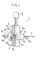
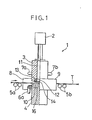
- FIG. 1 to Fig. 3 (.1) is an embodiment of electron beam irradiation apparatus of the present invention, comprising an electron beam source (2), a first magnet member (3), a second magnet member (4), film supporting/ shifting means, i.e., rollers (5a) (5b) and cooling means, i.e., coolant pipes (6a) (6b) (7a) (7b).
- film supporting/ shifting means i.e., rollers (5a) (5b)
- cooling means i.e., coolant pipes (6a) (6b) (7a) (7b).
- any of electron beam irradiation devices of the prior arts having an accelerator such as the Van de Graaff type, Cockcroft Walton type, transformer type or high frequency acceleration type may be used, without any particular limitation.
- the device which assures irradiation of electron beam with an acceleration energy of 150 KeV to 1000 KeV and electron current of 10mA to 200mA or more From the point of view of the shape of electron beam, the electron beam irradiation devices can be sorted into the two kinds.
- One is the scanning type where the belt shaped electron beam can substantially be obtained by scanning the elliptic beam spot of several millimeters and the other is non- scanning type where the belt shaped electron beam is directly obtained using the line shaped filament. Any kind of the apparatus may be employed.
- the first magnet member (3) and the second magnet member (4) are electromagnets which excite the soft iron core with excitation coils (8) (9). Excitation coil may be installed around center pole piece being provided with means to avoid electron irradiation. In a gap (10) formed by opposing magnets, a magnetic field as high as 500 - 20,000 Gauss, preferably 5,000 - 8,000 Gauss is formed.
- the meagnet members (3), (4) may have the N-pole or S-pole, so long as these are different in the polarities.
- the magnet members (3), (4) may be permanent magnets.
- the first magnet member (3) is provided with a bored through hole (11) which allows the electron beam to pass and a magnetic field shaping grill (13) having many apertures (12) is attached to the electron beam exit side of through hole (11).
- a bored through hole (11) which allows the electron beam to pass
- a magnetic field shaping grill (13) having many apertures (12) is attached to the electron beam exit side of through hole (11).
- disposition of the electron beam source (2) and the first magnet member (3) is not restricted but it is desirable from the point of view of constitution that the electron beam source (2) is disposed on the extended line of the through role (11) of the first magnet member (3).
- the grill (13) of through hole (11) is further provided with a metal foil (14).
- the metal foil (14) is made of titanium or titanium alloy in a thickness of 10 - 50 ⁇ m or aluminum or aluminum alloy foil in a thickness of 10 - 100 pm.
- This metal foil vacuumly seals an electron flight space between the electron beam source (.2) and the through hole (11).
- an inert gas such as nitrogen gas, rare gas or halogen gas.
- the area to be irradiated with electron beam may be in vacuo. In case the area to be irradiated with electron beam is vacuumed, the metal foil (14) may be eliminated because it is no longer necessary to provide vacuum sealing.
- An aperture area in the grill (13) is determined so that 20% or more, preferably 30 - 100% of the electron beam irradiated from the electron beam source (2) is transmitted to the area to be irradiated with electron beam.
- the shape of individual apertures (12) is selected to any shape of circle, rectangular, polygon or ellipse and it is desirable that individual aperture diameter is set smaller than the height of the gap (10) from the point of view of magnetic field shaping characteristic. As a practical example, when the height of gap (10) is 5 - 100 mm, the aperture is formed as a square having a side of 3 - 50 mm.
- a number of apertures (12) is uniquely determined from the aperture area but about 1 - 500 apertures are formed.
- the tape supporting/shifting rollers (5a)(5b) supports and shifts a tape (T) while it is positioned at the symmetrical surface of magnetic field of the gap (10).
- the coolant pipes (.6a)(6b) and (.7a)(7b) cool the magnetic members (3) (4) by allowing a refrigerant, for example, pure water, freon, etc. to flow into a cooling hole (15) provided to the first magnet member (3) and a cooling hole (16) provided to the second magnet member (4).
- a refrigerant for example, pure water, freon, etc.
- a magnetic paste dispersing magnetic particles is applied on a base material such as plastic film,to form the magnetic layer.
- Such magnetic particles are oriented for the vertical magnetic field by said electron beam irradiation apparatus (1). Simultaneously, such magnetic layer is hardened by electron beam irradiation.
- magnétique particles those which are suited to orientation for vertical magnetic field, for example, barium ferrite, y- Fe 2 0 3 , y-Fe 2 0 3 coated with Co , and Cr0 2 , etc. may be used
- the magnetic paste may be prepared by using a solution which is mainly composed of an unsaturated resin and a monomer which are hardened by electron beam irradiation and contains a small amount of a dispersant.
- unsaturated resins unsaturated polyester, acrylic polyester and unsaturated epoxy resin, etc. may be used.
- monomers acrylic acid ester, methacrylic acid ester, and vinyl hydrocarbon, etc. may be used.
- a base material which can be used as the carrier of magnetic layer of magnetic recording body may be used without any restriction on material and shape.
- a plastic film such as polyester, polyacetate, polyvinylchrolide and polyimide, etc. or vinylchloride resin plate, polyester resin plate and polymethylmethacrylate resin plate, etc. which are used as magnetic disk may be used.
- doctor blade method As a method of coating the base material with the magnetic paste dispersing magnetic particles, doctor blade method, reverse roll method, photogravure roll method and spinner method, etc. may be used. A coating apparatus which is usually used in this field may be freely employed. The layer is formed in the thickness of about 100 ⁇ m in maximum.
- the magnetic paste where needle-shaped ferromagnetic ferric oxide (with long axis of 1 ⁇ m or less) is dispersed uniformly into a solution consisting of solvent mainly composed of unsaturated polyester resin and aclyric acid ester, a stabilizier, a dispersant, a antistatic agent, a lubricant and a coloring agent, is applied, by the doctor blade method, on a polyester tape in the width of 15 cm - 2 m which is precoated in the thickness of 5 ⁇ m - 30 ⁇ m, thereby forming the magnetic layer film in the thickness of 1 ⁇ m - 10 pm.
- the tape (T) thus obtained is caused to run through the gap C10) by the tape supporting/ shifting rollers (5a) (5b) while the film (2) is not yet hardened at the rate of 50 m/min - 300 m/min, preferably at the rate of 10G m/min.
- the magnetic field perpendicular to the magnetic layer film of tape (T) works to the tape and the axis of easy magnetization of magnetic particles is oriented vertically to the running direction of tape (T).
- the film (2) is hardened by the electron beam irradiation, the vertical orientation is fixed and thereby the tape (T) forming suitably the vertical magnetization film can be manufactured continuously.
- the preferable amount of electron beam is 20 (kGy) - 100 (kGy).
- the electron beam partly collides with the first magnet member (3), the grill (13) of it and the metal foil (14), or transmits through the tape (T) and collides with the second magnet member (4). Therefore, the magnet members (3),(4) generate heat and is tien cooled by the refrigerant which flows through the coolant pipes (6a)(6b), (7a)(7b).
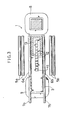
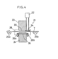
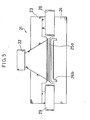
- Fig. 4 to Fig. 6, (21) is another embodiment of the electron beam irradiation apparatus to which the present invention is applied.
- This embodiment provides an electron beam source (22), first magnet member (23), second magnet member (24), film supporting/shifting rollers (25a)(25b) and coolant pipes (26a)(26b).
- the electron beam source (22) is the same as the electron beam source (2) in the constitution itself but is different in the position for the magnet members. Namely, the electron beam source (.22) is provided at the area near the single side of magnet members (23), (24). The internal space of the electron beam source (22) vacuumly sealed by metal foil (34) is highly vacuumed in such a degree of 10-4 - 10 -7 (Torr).
- the first magnet member (23) and second magnet member (24) are basically the same as the first magnet member (3) and the second magnet member (4). However, the through hole such as the hole (11) of said first magnet member (3) is not provided to this first magnet member (23). It may be sometimes allowed that the cooling means is not particularly provided to the first magnet member (23) because it generates less heat due to less collision of electron beam from its positional reason, but at least the second magnet member (24) generates a considerable amount of heat due to the scattered electron beam. Accordingly, a cooling hole (36) is provided and the second magnet member (24) can be cooled by a refrigerant which flows from the coolant pipes (26a),(26b). (28),(29) indicate the excitation coils.
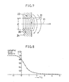
- the magnetic field (H) as shown in Fig. 7 is formed.
- both magnet members (23),(24) are disposed symmetrically each other, the magnetic field (H) becomes perpendicular to the center plane (m) at the center plane (m) of gap (30).
- the film supporting/shifting rollers (25a)(25b) supportingly shifts the film (T) keeping the center plane (m) from the side of magnet members (23)(24) where the electron beam source (22) is provided to the side where it is not provided. Therefore, when unhardened magnetic layer is formed on the film (T), the magnetic particles are sharply oriented vertically within the gap (30). At the outside of gap (30), the magnetic field becomes weak but since it is sufficient for keeping vertical orientation of magnetic particles already oriented vertically, the film is hardended by electron beam irradiation while the vertical orientation is being maintained. After all, the suitable vertical magnetic film can be obtained.
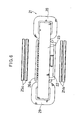
- Fig. 9 is another embodiment of apparatus equivalent to Fig. 4 but has another first and second magnet members (23a) (23b) on the other side of the electron beam source (22), by which efficient hardening of magnetic layer may be achieved.
Landscapes
- Chemical & Material Sciences (AREA)
- Analytical Chemistry (AREA)
- Dispersion Chemistry (AREA)
- Manufacturing Of Magnetic Record Carriers (AREA)
Applications Claiming Priority (2)
| Application Number | Priority Date | Filing Date | Title |
|---|---|---|---|
| JP238510/83 | 1983-12-16 | ||
| JP58238510A JPS60129700A (ja) | 1983-12-16 | 1983-12-16 | 電子線照射装置 |
Publications (3)
| Publication Number | Publication Date |
|---|---|
| EP0147746A2 true EP0147746A2 (de) | 1985-07-10 |
| EP0147746A3 EP0147746A3 (en) | 1987-01-07 |
| EP0147746B1 EP0147746B1 (de) | 1989-11-23 |
Family
ID=17031318
Family Applications (1)
| Application Number | Title | Priority Date | Filing Date |
|---|---|---|---|
| EP84115442A Expired EP0147746B1 (de) | 1983-12-16 | 1984-12-14 | Elektronenbestrahlungsgerät |
Country Status (4)
| Country | Link |
|---|---|
| US (1) | US4642467A (de) |
| EP (1) | EP0147746B1 (de) |
| JP (1) | JPS60129700A (de) |
| DE (1) | DE3480572D1 (de) |
Families Citing this family (5)
| Publication number | Priority date | Publication date | Assignee | Title |
|---|---|---|---|---|
| JPS63285499A (ja) * | 1987-05-18 | 1988-11-22 | Nissin High Voltage Co Ltd | ロ−ル方式窓箔自動交換装置 |
| US5053625A (en) * | 1988-08-04 | 1991-10-01 | Minnesota Mining And Manufacturing Company | Surface characterization apparatus and method |
| JPH052100A (ja) * | 1990-10-12 | 1993-01-08 | Toshiba Corp | 電子ビーム照射装置および電子ビーム透過膜の製造方法 |
| CA2591888A1 (en) * | 2007-06-11 | 2008-12-11 | Orren Johnson | Threaded connection |
| CN109487224A (zh) * | 2018-12-28 | 2019-03-19 | 湖畔光电科技(江苏)有限公司 | 一种新型磁控溅射装置 |
Family Cites Families (14)
| Publication number | Priority date | Publication date | Assignee | Title |
|---|---|---|---|---|
| US2897365A (en) * | 1956-09-28 | 1959-07-28 | High Voltage Engineering Corp | Irradiation method and apparatus |
| US3117065A (en) * | 1959-09-02 | 1964-01-07 | Magnetic Film And Tape Company | Method and apparatus for making magnetic recording tape |
| US3104321A (en) * | 1960-06-09 | 1963-09-17 | Temescal Metallurgical Corp | Apparatus for irradiating plastic tubular members with electrons deflected by a non-uniform magnetic field |
| US3676673A (en) * | 1969-08-18 | 1972-07-11 | Ppg Industries Inc | Apparatus for irradiation in a controlled atmosphere |
| DE2161083A1 (de) * | 1971-12-09 | 1973-06-14 | Basf Ag | Verfahren und vorrichtung zur herstellung bandfoermiger magnetogrammtraeger |
| DE2341040A1 (de) * | 1973-08-14 | 1975-02-27 | Kabel & Lackdrahtfab Gmbh | Verfahren zur vernetzung von isolierstoffschichten auf draehten durch bestrahlung mit elektronen |
| DE2606169C2 (de) * | 1976-02-17 | 1983-09-01 | Polymer-Physik GmbH & Co KG, 2844 Lemförde | Elektronenaustrittsfenster für eine Elektronenstrahlquelle |
| GB1600894A (en) * | 1977-03-23 | 1981-10-21 | Nat Res Inst Metals | Method and apparatus for removing burrs from products fabricated from metal stock |
| JPS57164436A (en) * | 1981-04-02 | 1982-10-09 | Fuji Photo Film Co Ltd | Manufacture of magnetic recording medium |
| JPS58159244A (ja) * | 1982-03-17 | 1983-09-21 | Ricoh Co Ltd | 磁気記録媒体の製造法 |
| EP0094452A3 (de) * | 1982-05-19 | 1986-01-02 | International Business Machines Corporation | Herstellung eines magnetischen Aufzeichnungsmediums mit senkrecht orientierten nadelförmigen Teilchen |
| JPS58203633A (ja) * | 1982-05-21 | 1983-11-28 | Fuji Photo Film Co Ltd | 磁気記録媒体の製法 |
| JPS58215732A (ja) * | 1982-06-09 | 1983-12-15 | Ricoh Co Ltd | 磁気記録媒体の製造方法 |
| JPH065575B2 (ja) * | 1982-06-17 | 1994-01-19 | 富士写真フイルム株式会社 | 磁気記録媒体の製造法 |
-
1983
- 1983-12-16 JP JP58238510A patent/JPS60129700A/ja active Granted
-
1984
- 1984-12-13 US US06/681,117 patent/US4642467A/en not_active Expired - Fee Related
- 1984-12-14 EP EP84115442A patent/EP0147746B1/de not_active Expired
- 1984-12-14 DE DE8484115442T patent/DE3480572D1/de not_active Expired
Also Published As
| Publication number | Publication date |
|---|---|
| US4642467A (en) | 1987-02-10 |
| DE3480572D1 (en) | 1989-12-28 |
| EP0147746A3 (en) | 1987-01-07 |
| JPH0444960B2 (de) | 1992-07-23 |
| EP0147746B1 (de) | 1989-11-23 |
| JPS60129700A (ja) | 1985-07-10 |
Similar Documents
| Publication | Publication Date | Title |
|---|---|---|
| US4441974A (en) | Magnetron sputtering apparatus | |
| US4543551A (en) | Apparatus for orienting magnetic particles in recording media | |
| CA1325792C (en) | Method of producing a thin film by sputtering and an opposed target type sputtering apparatus | |
| EP0242837A1 (de) | Magnetooptisches Aufzeichnungsgerät | |
| US4587066A (en) | Method and apparatus for forming magnetic recording media | |
| JP2002516495A (ja) | 磁気配向装置および磁気配向方法 | |
| EP0147746A2 (de) | Elektronenbestrahlungsgerät | |
| JP2004234865A (ja) | カーボンナノチューブ配列材料とその製造方法、炭素繊維配列材料とその製造方法、及び電界放出表示素子 | |
| JP2673807B2 (ja) | 光磁気記録媒体の製造方法 | |
| JPS58199862A (ja) | マグネトロン形スパツタ装置 | |
| JPH0337136Y2 (de) | ||
| JPH0337139Y2 (de) | ||
| JPH04242196A (ja) | 挿入光源用磁気回路の磁場強度調整方法 | |
| JP2821622B2 (ja) | 斜め配向装置 | |
| US20030221781A1 (en) | Milling apparatus | |
| JPH0337138Y2 (de) | ||
| JPH06103530B2 (ja) | 磁気記録媒体の製法 | |
| JPH1161405A (ja) | スパッタリング装置 | |
| JPS6013069A (ja) | 薄膜形成方法 | |
| JPS59193542A (ja) | 磁気記録媒体の製造方法 | |
| JPH09143714A (ja) | スパッタリング装置 | |
| JPS63171428A (ja) | 磁気記録媒体製造装置 | |
| JPS5917896Y2 (ja) | 高速スパツタ用タ−ゲツト電極 | |
| JPH0337137Y2 (de) | ||
| Ohta et al. | Current‐access ion‐implanted bubble device structure |
Legal Events
| Date | Code | Title | Description |
|---|---|---|---|
| PUAI | Public reference made under article 153(3) epc to a published international application that has entered the european phase |
Free format text: ORIGINAL CODE: 0009012 |
|
| AK | Designated contracting states |
Designated state(s): DE FR NL |
|
| PUAL | Search report despatched |
Free format text: ORIGINAL CODE: 0009013 |
|
| AK | Designated contracting states |
Kind code of ref document: A3 Designated state(s): DE FR NL |
|
| 17P | Request for examination filed |
Effective date: 19870508 |
|
| 17Q | First examination report despatched |
Effective date: 19880428 |
|
| RAP1 | Party data changed (applicant data changed or rights of an application transferred) |
Owner name: NISSIN-HIGH VOLTAGE CO., LTD. |
|
| GRAA | (expected) grant |
Free format text: ORIGINAL CODE: 0009210 |
|
| AK | Designated contracting states |
Kind code of ref document: B1 Designated state(s): DE FR NL |
|
| REF | Corresponds to: |
Ref document number: 3480572 Country of ref document: DE Date of ref document: 19891228 |
|
| ET | Fr: translation filed | ||
| PLBE | No opposition filed within time limit |
Free format text: ORIGINAL CODE: 0009261 |
|
| STAA | Information on the status of an ep patent application or granted ep patent |
Free format text: STATUS: NO OPPOSITION FILED WITHIN TIME LIMIT |
|
| 26N | No opposition filed | ||
| PGFP | Annual fee paid to national office [announced via postgrant information from national office to epo] |
Ref country code: FR Payment date: 19951127 Year of fee payment: 12 |
|
| PGFP | Annual fee paid to national office [announced via postgrant information from national office to epo] |
Ref country code: DE Payment date: 19951218 Year of fee payment: 12 |
|
| PGFP | Annual fee paid to national office [announced via postgrant information from national office to epo] |
Ref country code: NL Payment date: 19951230 Year of fee payment: 12 |
|
| PG25 | Lapsed in a contracting state [announced via postgrant information from national office to epo] |
Ref country code: NL Effective date: 19970701 |
|
| PG25 | Lapsed in a contracting state [announced via postgrant information from national office to epo] |
Ref country code: FR Effective date: 19970829 |
|
| NLV4 | Nl: lapsed or anulled due to non-payment of the annual fee |
Effective date: 19970701 |
|
| PG25 | Lapsed in a contracting state [announced via postgrant information from national office to epo] |
Ref country code: DE Effective date: 19970902 |
|
| REG | Reference to a national code |
Ref country code: FR Ref legal event code: ST |