EP0146790B1 - Vakuumgehäuse, insbesondere Gehäuse eines Vakuumschalters - Google Patents
Vakuumgehäuse, insbesondere Gehäuse eines Vakuumschalters Download PDFInfo
- Publication number
- EP0146790B1 EP0146790B1 EP84114142A EP84114142A EP0146790B1 EP 0146790 B1 EP0146790 B1 EP 0146790B1 EP 84114142 A EP84114142 A EP 84114142A EP 84114142 A EP84114142 A EP 84114142A EP 0146790 B1 EP0146790 B1 EP 0146790B1
- Authority
- EP
- European Patent Office
- Prior art keywords
- cap
- housing
- vacuum
- pumping lead
- tube
- Prior art date
- Legal status (The legal status is an assumption and is not a legal conclusion. Google has not performed a legal analysis and makes no representation as to the accuracy of the status listed.)
- Expired
Links
- 238000003466 welding Methods 0.000 claims description 7
- 238000000034 method Methods 0.000 claims description 6
- 239000011810 insulating material Substances 0.000 claims description 5
- 238000005086 pumping Methods 0.000 claims 10
- 229920003002 synthetic resin Polymers 0.000 claims 3
- 239000000057 synthetic resin Substances 0.000 claims 3
- 238000009413 insulation Methods 0.000 description 4
- 239000002184 metal Substances 0.000 description 3
- 239000000853 adhesive Substances 0.000 description 2
- 230000001070 adhesive effect Effects 0.000 description 2
- 238000005452 bending Methods 0.000 description 1
- 230000015556 catabolic process Effects 0.000 description 1
- 239000000919 ceramic Substances 0.000 description 1
- 230000005684 electric field Effects 0.000 description 1
- 239000003292 glue Substances 0.000 description 1
- 238000009434 installation Methods 0.000 description 1
- 238000002955 isolation Methods 0.000 description 1
- 238000004519 manufacturing process Methods 0.000 description 1
- 238000007789 sealing Methods 0.000 description 1
Images

Classifications
-
- H—ELECTRICITY
- H01—ELECTRIC ELEMENTS
- H01H—ELECTRIC SWITCHES; RELAYS; SELECTORS; EMERGENCY PROTECTIVE DEVICES
- H01H33/00—High-tension or heavy-current switches with arc-extinguishing or arc-preventing means
- H01H33/60—Switches wherein the means for extinguishing or preventing the arc do not include separate means for obtaining or increasing flow of arc-extinguishing fluid
- H01H33/66—Vacuum switches
- H01H33/662—Housings or protective screens
- H01H33/66207—Specific housing details, e.g. sealing, soldering or brazing
-
- H—ELECTRICITY
- H01—ELECTRIC ELEMENTS
- H01H—ELECTRIC SWITCHES; RELAYS; SELECTORS; EMERGENCY PROTECTIVE DEVICES
- H01H33/00—High-tension or heavy-current switches with arc-extinguishing or arc-preventing means
- H01H33/60—Switches wherein the means for extinguishing or preventing the arc do not include separate means for obtaining or increasing flow of arc-extinguishing fluid
- H01H33/66—Vacuum switches
- H01H33/662—Housings or protective screens
- H01H33/66207—Specific housing details, e.g. sealing, soldering or brazing
- H01H2033/66223—Details relating to the sealing of vacuum switch housings
-
- H—ELECTRICITY
- H01—ELECTRIC ELEMENTS
- H01H—ELECTRIC SWITCHES; RELAYS; SELECTORS; EMERGENCY PROTECTIVE DEVICES
- H01H33/00—High-tension or heavy-current switches with arc-extinguishing or arc-preventing means
- H01H33/60—Switches wherein the means for extinguishing or preventing the arc do not include separate means for obtaining or increasing flow of arc-extinguishing fluid
- H01H33/66—Vacuum switches
- H01H33/662—Housings or protective screens
- H01H33/66207—Specific housing details, e.g. sealing, soldering or brazing
- H01H2033/6623—Details relating to the encasing or the outside layers of the vacuum switch housings
Definitions
- the present invention relates to a vacuum housing, in particular a housing of a vacuum switch, with a pump stem which is closed in a vacuum-tight manner according to the preamble of patent claim 1.
- Such a vacuum housing is known from DE-C-24 40 828.
- the pump stem is insulated by a shrink tube or a cap, the wall of the shrink tube or the cap consisting of a cross-linked, non-meltable plastic in the area of the outer wall and a non-cross-linked, meltable plastic in the area of the inner wall.
- Pulp stem is usually understood to mean a pipe socket on a vacuum housing, which is used in the manufacture to empty the vacuum housing and is then closed in a vacuum-tight manner.
- the vacuum-tight sealing is usually carried out by compressing the stem, which results in a vacuum-tight cold welding of the stem walls.
- the object of the present invention is to improve the insulation and the mechanical protection for the pump stem and at the same time to find a cost-saving solution.
- caps for insulation purposes are a common procedure in another context.
- the caps are usually pressed onto the objects to be supported. They either hold due to a slight deformation when they are pressed on or through specially designed snap-in devices.
- attachment of caps when used to protect pump stems, easily leads to damage to the vacuum-tight cold welding of the pump stem.
- this attachment requires a fixation option for the cap in the form of lugs, grooves or the like on the side of the pump stem, which increases the cost of producing the tube.
- the vacuum housing according to the invention has the advantage that the distances between housing parts, which can be at different potential during operation, can be dimensioned relatively small.
- the inventive isolation of the pump stem enables the holding function for the pump stem protection to be separated from the insulation without the pump stem being subjected to an impermissibly high mechanical load.
- the invention enables the use of very small caps, which only cover the cutting-shaped end area of the stem. It is well known that the areas of greatest electric field strength, particularly at corners and edges, tend to form breakdowns.
- the shrink tube need not be closed at its free end in the embodiment according to the invention. It is sufficient if he clasps the cap so far that he fixes it mechanically.
- Another advantage of the invention is that arcing cannot pass through the opening of the shrink tube to the pump stem. If only shrink sleeves are pushed over the pump stem, a rollover can reach the pump stem through the opening of the shrink tube even if the shrink tube is pressed together so flatly at its end that its inner walls are glued together. This danger does not exist in the embodiment according to the invention.
- a particularly cost-saving embodiment is provided in that the end region of the pump stem is flattened by a pressure welding process and closed in a vacuum-tight manner and by a circular cylindrical cap being placed thereon. Circular cylindrical caps can be applied regardless of an angular position to the edge area of the stem.
- the shrink tube attaches particularly precisely to such caps, and the shrink tube itself has to meet particularly low requirements.
- caps can be used by using a cap which is flattened by a pressure welding and which is sealed in a vacuum-tight manner on a pump stem, the shape of this edge region being adapted.
- a cap can be made particularly small. It particularly protects the edges and corners in the end area of the pump stem against flashovers. In this case, it is advisable to compress the shrink tube flat outside the cap and thereby glue it together.
- the cap in the case of a round cap shape in particular, it is advantageous that the cap also partially covers the area of the pump stem that is not flattened. This prevents the cap from tilting too much during installation.
- the cap advantageously consists of a plastic with a high dielectric constant.
- a particularly good bond is achieved if the shrink tube consists of a cross-linked, non-meltable plastic in the area of its outer walls and a non-cross-linked, meltable plastic in the area of its inner walls.
- shrink sleeves have a particularly high mechanical strength and a high adhesive capacity on their inner wall.
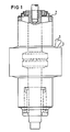
- FIG. 1 shows an inventive vacuum vessel of a vacuum interrupter
- FIGS. 2 to 4 show different embodiments of pump stems protected according to the invention, in a cut and broken view.
- the pump stem 1 is temporarily at different potential compared to the metal flange 2, whereby flashovers from the metal flange 2 to the pump stem 1 may occur, but not from the metal flange 2 to the housing part 3 surrounding the pump stem 1.
- the pump stem 1 is compressed so strongly in its edge region 6 that a vacuum-tight closure of the pump stem 1 is created by a cold welding process.
- This edge area 6 is sensitive to mechanical stress, in particular since a bending or pressure stress in places is sufficient to make the vacuum-tight weld leak.
- an insulating material cap 8 which is cylindrical in shape as shown in FIG. 4 is placed on the pump stem 1.
- This insulating material cap is preferably made of a plastic with a high dielectric constant. It is dimensioned for sufficient voltage insulation.
- This insulating material cap 8 is encased by a shrink tube 4 to such an extent that it cannot move in the shrink tube 4.
- the shrink tube 4 also abuts the pump stem 1. It is preferably additionally glued to this pump stem 1.
- the cap 3 does not have to fit positively on the pump stem 1 everywhere. It is sufficient that it covers the sharp-edged and cornered edge area 6 to such an extent that punctures through the shrink tube 4, which could arise due to the high field strength in the edge area 6, are avoided.
- the shrink tube 4 holds the cap 8 in position after being shrink-fitted and protects the areas of the pump stem with a field strength that is less high in comparison to the edge area (FIG. 2).
- a cap 7 is provided which is adapted to the shape of the edge area 6. It only encloses the area of particularly high field strength. It can therefore be made particularly small. It can also consist of a plastic with a high dielectric constant. Because of its flat shape and its small expansion, it can advantageously also be produced from other insulating materials, for example from ceramic.
- a suitable shrink tube preferably consists of a cross-linked, non-meltable plastic in the area of its outer wall and a non-cross-linked, meltable plastic in the area of its inner wall.
Landscapes
- High-Tension Arc-Extinguishing Switches Without Spraying Means (AREA)
Description
- Die vorliegende Erfindung betrifft ein Vakuumgehäuse, insbesondere ein Gehäuse eines Vakuumschalters, mit einem vakuumdicht verschlossenen Pumpstengel gemäß dem Oberbegriff des Patentanspruchs 1.
- Ein derartiges Vakuumgehäuse ist aus der DE-C-24 40 828 bekannt. Dort ist der Pumpstengel durch einen Schrumpfschlauch oder eine Kappe isoliert, wobei die Wand des Schrumpfschlauches oder der Kappe im Bereich der Außenwand aus einem vernetzten, nicht schmelzbaren und im Bereich der Innenwand aus einem nicht vernetzten, schmelzbaren Kunststoff besteht.
- Als "Pumpstengel" wird üblicherweise ein Rohrstutzen an einem Vakuumgehäuse verstanden, welcher bei der Herstellung zum Leerpumpen des Vakuumgehäuses verwendet und anschließend vakuumdicht verschlossen wird. Das vakuumdichte Verschließen erfolgt üblicherweise durch ein Zusammenpressen des Pumpstengels, wodurch sich eine vakuumdichte Kaltverschweißung der Pumpstengelwände ergibt.
- Ein Schrumpfschlauch oder eine schrumpfende Kappe legen sich beim Schrumpfungsprozeß eng an den darunter liegenden Pumpstengel an. Dabei entstehen gemäß unserer Erkenntnis im Bereich der Ecken und Kanten des Pumpstengels nicht mehr ausreichend isolierte Stellen, es treten Überschläge zu benachbarten Gehäuseteilen auf, welche auf anderem Potenial liegen. Diese Durchschläge wurden bisher durch Aufschrumpfen eines zweiten Schrumpfschlauches vermieden.
- Gegenüber dieser Lösung liegt der vorliegenden Erfindung die Aufgabe zugrunde, die Isolation und den mechanischen Schutz für den Pumpstengel zu verbessern und gleichzeitig eine kostensparende Lösung zu finden.
- Diese Aufgabe wird durch die kennzeichnenden Merkmale des Patentanspruchs 1 gelöst.
- Das Aufbringen von Kappen zu Isolationszwecken ist ein in anderem Zusammenhang übliches Verfahren. Die Kappen werden üblicherweise auf die zu stützenden Gegenstände aufgedrückt. Sie halten entweder durch eine geringfügige Verformung beim Aufdrücken oder durch eigens hierfür vorgesehene Snap-in-Einrichtungen. Eine derartige Befestigung von Kappen führt beim Einsatz zum Schutz von Pumpstengeln gemäß unserer Erkenntnis leicht zu einer Beschädigung der vakuumdichten Kaltverschweißung des Pumpstengels. Weiterhin erfordert diese Befestigung pumpstengelseitig eine Fixierungsmöglichkeit für die Kappe in Form von Nasen, Nuten oder dergleichen, welche die Herstellung der Röhre verteuert.
- Das erfindungsgemäße Vakuumgehäuse hat den Vorteil, daß die Abstände zwischen Gehäuseteilen, die beim Betrieb auf unterschiedlichem Potential liegen können, relativ klein dimensioniert sein können. Die erfindungsgemäße Isolation des Pumpstengels ermöglicht eine Trennung der Haltefunktion für den Pumpstengelschutz von der Isolation, ohne daß der Pumpstengel unzulässig stark mechanisch belastet wird. Gleichzeitig ermöglicht die Erfindung die Verwendung sehr kleiner Kappen, welche nur den schneidenförmigen Endbereich des Pumpstengels überdecken. Gerade an Ekken und Kanten sind ja bekanntlich die Bereiche größter elektrischer Feldstärke, die besonders zur Bildung von Durchschlägen neigen.
- Der Schrumpfschlauch braucht bei der erfindungsgemäßen Ausführungsform an seinem freien Ende nicht geschlossen zu sein. Es genügt, wenn er die Kappe so weit umklammert, daß er sie mechanisch fixiert.
- Ein weiterer Vorteil der Erfindung besteht darin, daß Überschläge nicht durch die Öffnung des Schrumpfschlauches hindurch zum Pumpstengel gelangen können. Werden nur Schrumpfschläuche über den Pumpstengel geschoben, so kann selbst dann ein Überschlag durch die Öffnung des Schrumpfschlauches hindurch zum Pumpstengel gelangen, wenn der Schrumpfschlauch an seinem Ende so stark flach zusammengedrückt ist, daß seine Innenwände miteinander verklebt sind. Diese Gefahr besteht bei der erfindungsgemäßen Ausführungsform nicht.
- Eine besonders kostensparende Ausführungsform ist gegeben, indem der Endbereich des Pumpstengels durch einen Preßschweißvorgang flachgedrückt und vakuumdicht verschlossen ist und indem auf diesen eine kreiszylinderförmige Kappe aufgesetzt ist. Kreiszylinderförmige Kappen können ohne Rücksicht auf eine Winkelstellung zum Randbereich des Pumpstengels aufgebracht werden. An derartige Kappen legt sich außerdem der Schrumpfschlauch besonders genau an, an den Schrumpfschlauch selbst sind besonders geringe Anforderungen zu stellen.
- Wesentlich kleinere Kappen können verwendet werden, indem bei einem Pumpstengel, dessen Randbereich durch ein Preßschweißen flachgedrückt und vakuumdicht verschlossen ist, eine der Form dieses Randbereiches angepaßte Kappe verwendet ist. Eine derartige Kappe kann besonders klein ausgeführt werden. Sie schützt insbesondere die Kanten und Ecken im Endbereich des Pumpstengels gegen Überschläge. In diesem Fall ist es zweckmäßig, den Schrumpfschlauch außerhalb der Kappe flach zusammenzupressen und dadurch zu verkleben.
- Insbesondere bei einer runden Kappenform ist es vorteilhaft, daß die Kappe auch den nicht flachgedrückten Bereich des Pumpstengels teilweise umfaßt. Dadurch wird ein allzu starkes Verkippen der Kappe beim Einbau vermieden. Die Kappe besteht vorteilhaft aus einem Kunststoff mit hoher Dielektrizitätskonstante. Eine besonders gute Verklebung wird erreicht, indem der Schrumpfschlauch im Bereich seiner Außenwände aus einem vernetzten, nichtschmelzbaren und im Bereich seiner Innenwände aus einem nichtvernetzten, schmelzbaren Kunststoff besteht. Derartige Schrumpfschläuche besitzen eine besonders hohe mechanische Festigkeit und eine hohe Klebefähigkeit an ihrer Innenwand.
- Die Erfindung wird nun anhand von vier Figuren näher erläutert.
- Figur 1 zeigt ein erfindungsgemäßes Vakuumgefäß einer Vakuumschaltröhre,
die Figuren 2 bis 4 zeigen verschiedene Ausführungsformen von erfindungsgemäß geschützten Pumpstengeln, in geschnittener und gebrochener Ansicht. - In Fig. 1 liegt der Pumpstengel 1 gegenüber dem Metallflansch 2 zeitweise auf unterschiedlichem Potential, wobei Überschläge vom Metallflansch 2 auf den Pumpstengel 1 auftreten können, nicht aber vom Metallflansch 2 auf das den Pumpstengel 1 umgebende Gehäuseteil 3.
- Wie aus den Figuren 2 bis 4 ersichtlich, ist der Pumpstengel 1 ist in seinem Randbereich 6 so kräftig zusammengedrückt, daß durch einen Kaltschweißvorgang ein vakuumdichter Verschluß des Pumpstengels 1 entstanden ist. Dieser Randbereich 6 ist gegenüber mechanischer Beanspruchung empfindlich, insbesondere da bereits eine stellenweise Verbiegung oder Druckbeanspruchung genügt, um die vakuumdichte Verschweißung undicht werden zu lassen. Um einen Überschlag auf diesen Randbereich zu vermieden, ohne daß der Randbereich mechanisch beansprucht wird, ist auf den Pumpstengel 1 eine gemäß Fig. 4 kreiszylinderförmige Isolierstoffkappe 8 aufgesetzt. Diese Isolierstoffkappe besteht vorzugsweise aus einem Kunststoff mit hoher Dielektrizitätskonstante. Sie ist auf eine ausreichende Spannungsisolation hin dimensioniert. Diese Isolierstoffkappe 8 ist von einem Schrumpfschlauch 4 so weit umhüllt, daß sie sich im Schrumpfschlauch 4 nicht verschieben kann. Der Schrumpfschlauch 4 liegt außerdem am Pumpstengel 1 an. Er ist vorzugsweise mit diesem Pumpstengel 1 zusätzlich verklebt.
- Die Kappe 3 braucht am Pumpstengel 1 nicht überall formschlüssig anzuliegen. Es genügt, daß sie den scharfkantigen und mit Ecken versehenen Randbereich 6 so weit abdeckt, daß Durchschläge durch den Schrumpfschlauch 4, die infolge der hohen Feldstärke im Randbereich 6 entstehen könnten, vermieden werden. Der Schrumpfschlauch 4 hält die Kappe 8 nach dem Aufschrumpfen in ihrer Lage und schützt die Bereiche des Pumpstengels mit im Vergleich zum Randbereich weniger hoher Feldstärke vor Überschlägen (Fig. 2).
- In der Ausführungsform gemäß Fig. 3 ist eine Kappe 7 vorgesehen, welche an die Form des Randbereiches 6 angepaßt ist. Sie umschließt nur den Bereich besonders hoher Feldstärke. Sie kann daher besonders klein ausgeführt sein. Sie kann ebenfalls aus einem Kunststoff mit hoher Dielektrizitätskonstante bestehen. Wegen ihrer flachen Gestalt und ihrer geringen Ausdehnung kann sie vorteilhaft auch aus anderen Isolierstoffen, beispielsweise aus Keramik, hergestellt werden.
- Der Schrumpfschlauch 5 ist in diesem Ausführungsbeispiel außerhalb der Isolierstoff kappe 7 zusammengedrückt, seine Innenwände sind miteinander verklebt. Dadurch entsteht bei dieser relativ flachen Bauform ein guter Halt. Im Gegensatz zum Stand der Technik kann durch die Klebestelle 9 hindurch keine elektrische Entladung zum Randbereich 6 des Pumpstengels 1 gelangen. Ein hierfür geeigneter Schrumpfschlauch besteht vorzugsweise im Bereich seiner Außenwand aus einem vernetzten, nicht schmelzbaren und im Bereich seiner Innenwand aus einem nicht vernetzten, schmelzbaren Kunststoff.
Claims (6)
Applications Claiming Priority (3)
| Application Number | Priority Date | Filing Date | Title |
|---|---|---|---|
| DE3344895 | 1983-12-12 | ||
| DE8335618U DE8335618U1 (de) | 1983-12-12 | 1983-12-12 | Vakuumgehäuse, insbesondere Gehäuse eines Vakuumschalters |
| DE19833344895 DE3344895A1 (de) | 1983-12-12 | 1983-12-12 | Vakuumgehaeuse, insbesondere gehaeuse eines vakuumschalters |
Publications (2)
| Publication Number | Publication Date |
|---|---|
| EP0146790A1 EP0146790A1 (de) | 1985-07-03 |
| EP0146790B1 true EP0146790B1 (de) | 1987-09-02 |
Family
ID=25816362
Family Applications (1)
| Application Number | Title | Priority Date | Filing Date |
|---|---|---|---|
| EP84114142A Expired EP0146790B1 (de) | 1983-12-12 | 1984-11-22 | Vakuumgehäuse, insbesondere Gehäuse eines Vakuumschalters |
Country Status (3)
| Country | Link |
|---|---|
| EP (1) | EP0146790B1 (de) |
| JP (1) | JPS60157123A (de) |
| DE (2) | DE8335618U1 (de) |
Cited By (1)
| Publication number | Priority date | Publication date | Assignee | Title |
|---|---|---|---|---|
| DE3717864A1 (de) * | 1987-05-26 | 1988-11-17 | Slamecka Ernst | Vakuumschalter |
Family Cites Families (3)
| Publication number | Priority date | Publication date | Assignee | Title |
|---|---|---|---|---|
| DE2152527A1 (de) * | 1970-10-26 | 1972-04-27 | Int Standard Electric Corp | Vakuumschalter,der durch elastische Verformung des Gehaeuses betaetigt wird |
| JPS4893351A (de) * | 1972-03-09 | 1973-12-03 | ||
| DE2440828C3 (de) * | 1974-08-26 | 1980-12-18 | Siemens Ag, 1000 Berlin Und 8000 Muenchen | Pumpstengelschutzhülle für ein Vakuumschaltrohr |
-
1983
- 1983-12-12 DE DE8335618U patent/DE8335618U1/de not_active Expired
- 1983-12-12 DE DE19833344895 patent/DE3344895A1/de not_active Withdrawn
-
1984
- 1984-11-22 EP EP84114142A patent/EP0146790B1/de not_active Expired
- 1984-12-10 JP JP59261674A patent/JPS60157123A/ja active Pending
Cited By (1)
| Publication number | Priority date | Publication date | Assignee | Title |
|---|---|---|---|---|
| DE3717864A1 (de) * | 1987-05-26 | 1988-11-17 | Slamecka Ernst | Vakuumschalter |
Also Published As
| Publication number | Publication date |
|---|---|
| DE8335618U1 (de) | 1986-01-16 |
| DE3344895A1 (de) | 1985-06-13 |
| JPS60157123A (ja) | 1985-08-17 |
| EP0146790A1 (de) | 1985-07-03 |
Similar Documents
| Publication | Publication Date | Title |
|---|---|---|
| DE69508145T2 (de) | Isolationsanordnung für ein geschweisstes hermetisches Endstück | |
| DE2309825C2 (de) | Durchführung in Metall-Glas-Einschmelztechnik | |
| DE69226084T2 (de) | Hochspannungskondensator und magnetron | |
| EP2431982B1 (de) | Steckbare Durchführung und Hochspannungsanlage mit einer solchen Durchführung | |
| DE3887725T2 (de) | Vakuum-Entladevorrichtung. | |
| DE3105133C2 (de) | Gasisolierter Trennschalter | |
| DE2624908C2 (de) | Scheibenförmiger Stützisolator für eine dreiphasig gekapselte, druckgasisolierte Hochspannungsleitung | |
| EP0843395A2 (de) | Kapselungsgehäuse für gasisolierte, metallgekapselte Schaltanlagen | |
| EP0146790A1 (de) | Vakuumgehäuse, insbesondere Gehäuse eines Vakuumschalters | |
| DE2343075A1 (de) | Selbstbindende isolation fuer ein kondensatorgehaeuse | |
| EP0920705B2 (de) | Lastschalter | |
| EP0662240B1 (de) | Vakuumschutz mit einer anschlussvorrichtung | |
| EP1249850B1 (de) | Isoliergehäuse, insbesondere Gehäuse einer Schaltröhre eines Vakuumschalters, mit einer Halterung zur Positionierung einer Steuerelektrode | |
| DE3231864C2 (de) | Elektrischer Becherkondensator mit Überdruck-Abschaltsicherung | |
| DE2925307A1 (de) | Vakuum-leistungsschalter | |
| DD241810A1 (de) | Schalterpol fuer leistungsschalter | |
| DE10105863C1 (de) | Kondensator mit einer Überdruck-Abreisssicherung | |
| EP0284927B1 (de) | Elektrischer Kondensator | |
| DE4302420C1 (de) | Elektrischer Becherkondensator mit Überdruck-Abschaltsicherung | |
| DE3717864A1 (de) | Vakuumschalter | |
| DE2650468A1 (de) | Elektrischer kondensator | |
| DE2815232C3 (de) | Aufschiebbarer Endverschluß für kunststoffisolierte Kabel im Mittelspannungsbereich | |
| EP0023543A2 (de) | Explosionssicherer elektrischer Kondensator mit Abschaltsicherung | |
| DE69822688T2 (de) | Potentialsteuerkappe | |
| DE7722435U1 (de) | Elektrischer apparat, insbesondere transformator oder messwandler |
Legal Events
| Date | Code | Title | Description |
|---|---|---|---|
| PUAI | Public reference made under article 153(3) epc to a published international application that has entered the european phase |
Free format text: ORIGINAL CODE: 0009012 |
|
| 17P | Request for examination filed |
Effective date: 19841205 |
|
| AK | Designated contracting states |
Designated state(s): CH DE FR GB IT LI SE |
|
| 17Q | First examination report despatched |
Effective date: 19861106 |
|
| GRAA | (expected) grant |
Free format text: ORIGINAL CODE: 0009210 |
|
| AK | Designated contracting states |
Kind code of ref document: B1 Designated state(s): CH DE FR GB IT LI SE |
|
| REF | Corresponds to: |
Ref document number: 3465826 Country of ref document: DE Date of ref document: 19871008 |
|
| ET | Fr: translation filed | ||
| ITF | It: translation for a ep patent filed | ||
| GBT | Gb: translation of ep patent filed (gb section 77(6)(a)/1977) | ||
| PLBE | No opposition filed within time limit |
Free format text: ORIGINAL CODE: 0009261 |
|
| STAA | Information on the status of an ep patent application or granted ep patent |
Free format text: STATUS: NO OPPOSITION FILED WITHIN TIME LIMIT |
|
| 26N | No opposition filed | ||
| PG25 | Lapsed in a contracting state [announced via postgrant information from national office to epo] |
Ref country code: SE Effective date: 19891123 |
|
| PG25 | Lapsed in a contracting state [announced via postgrant information from national office to epo] |
Ref country code: FR Effective date: 19900731 |
|
| REG | Reference to a national code |
Ref country code: FR Ref legal event code: ST |
|
| PGFP | Annual fee paid to national office [announced via postgrant information from national office to epo] |
Ref country code: CH Payment date: 19920221 Year of fee payment: 8 |
|
| PGFP | Annual fee paid to national office [announced via postgrant information from national office to epo] |
Ref country code: GB Payment date: 19921016 Year of fee payment: 9 |
|
| PG25 | Lapsed in a contracting state [announced via postgrant information from national office to epo] |
Ref country code: LI Effective date: 19921130 Ref country code: CH Effective date: 19921130 |
|
| REG | Reference to a national code |
Ref country code: CH Ref legal event code: PL |
|
| PG25 | Lapsed in a contracting state [announced via postgrant information from national office to epo] |
Ref country code: GB Effective date: 19931122 |
|
| GBPC | Gb: european patent ceased through non-payment of renewal fee |
Effective date: 19931122 |
|
| EUG | Se: european patent has lapsed |
Ref document number: 84114142.7 Effective date: 19900705 |
|
| PGFP | Annual fee paid to national office [announced via postgrant information from national office to epo] |
Ref country code: DE Payment date: 19970121 Year of fee payment: 13 |
|
| PG25 | Lapsed in a contracting state [announced via postgrant information from national office to epo] |
Ref country code: DE Free format text: LAPSE BECAUSE OF NON-PAYMENT OF DUE FEES Effective date: 19980801 |