EP0146435B1 - Vorrichtung zum Umblättern von Seiten eines Buches - Google Patents
Vorrichtung zum Umblättern von Seiten eines Buches Download PDFInfo
- Publication number
- EP0146435B1 EP0146435B1 EP19840402274 EP84402274A EP0146435B1 EP 0146435 B1 EP0146435 B1 EP 0146435B1 EP 19840402274 EP19840402274 EP 19840402274 EP 84402274 A EP84402274 A EP 84402274A EP 0146435 B1 EP0146435 B1 EP 0146435B1
- Authority
- EP
- European Patent Office
- Prior art keywords
- arm
- rotation
- assembly
- page
- bushing
- Prior art date
- Legal status (The legal status is an assumption and is not a legal conclusion. Google has not performed a legal analysis and makes no representation as to the accuracy of the status listed.)
- Expired
Links
- 230000033001 locomotion Effects 0.000 claims description 20
- 230000001360 synchronised effect Effects 0.000 claims description 4
- 230000000284 resting effect Effects 0.000 claims description 2
- 230000007717 exclusion Effects 0.000 claims 3
- 239000012780 transparent material Substances 0.000 claims 1
- 238000005192 partition Methods 0.000 description 2
- 239000007787 solid Substances 0.000 description 2
- 235000008612 Gnetum gnemon Nutrition 0.000 description 1
- 240000000018 Gnetum gnemon Species 0.000 description 1
- 230000006978 adaptation Effects 0.000 description 1
- 230000001419 dependent effect Effects 0.000 description 1
- 230000000994 depressogenic effect Effects 0.000 description 1
- 238000006073 displacement reaction Methods 0.000 description 1
- 230000001681 protective effect Effects 0.000 description 1
- 238000007789 sealing Methods 0.000 description 1
Images


Classifications
-
- B—PERFORMING OPERATIONS; TRANSPORTING
- B42—BOOKBINDING; ALBUMS; FILES; SPECIAL PRINTED MATTER
- B42D—BOOKS; BOOK COVERS; LOOSE LEAVES; PRINTED MATTER CHARACTERISED BY IDENTIFICATION OR SECURITY FEATURES; PRINTED MATTER OF SPECIAL FORMAT OR STYLE NOT OTHERWISE PROVIDED FOR; DEVICES FOR USE THEREWITH AND NOT OTHERWISE PROVIDED FOR; MOVABLE-STRIP WRITING OR READING APPARATUS
- B42D9/00—Bookmarkers; Spot indicators; Devices for holding books open; Leaf turners
- B42D9/04—Leaf turners
- B42D9/06—Leaf turners having an arm reset after each operation
Definitions
- the subject of the invention is a device adaptable to a support desk for a book and making it possible to turn the pages on demand without the aid of the hands or of another person. It can therefore be useful for people who cannot use their hands because they are either inoperative when they are disabled, or unavailable as, for example, in the case of musicians.
- the suction member is only used to take off the page to allow a pusher to come and stand behind the page to complete its rotation.
- the pusher is actuated by a rod mounted to rotate about an eccentric axis and rotating at a different speed. Such a device is therefore relatively complicated.
- the subject of the invention is a simpler arrangement using a single drive arm to take off the page and to make it turn.
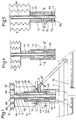
- a desk 1 which can be of any conventional type, and in particular comprises a support 11 of adjustable height consisting of a strip on which the book or the partition 12 is placed.
- the apparatus is mounted on a fixed part essentially constituted by a tubular rod 2 mounted on a clamp 21 which is removably fixed on the desk 1, the book being placed so that the axis of its back is practically aligned with the axis 20 of the tubular rod 2.
- the device is placed above the desk and the drive arm can therefore slide vertically between a high position and a low position for which the suction member will be placed, respectively, outside. and inside the page. It is obvious that by making the necessary adaptations, the device could be placed above the book, the desk being able, moreover, to be oriented horizontally.
- a transverse plate 32 on which bears a cylindrical bellows 3 centered on the axis 20 of the rod 2 and which is interposed between the fixed plate 32 and a movable plate 34 which can slide axially , but without turning, along the rod 2 while remaining perpendicular to the axis 20 thereof.
- a second coaxial bellows 35 Inside the bellows 3 is placed a second coaxial bellows 35, of smaller diameter, so as to delimit a central space 36 inside the bellows 35 and an annular space 37 between the two bellows 3 and 35.
- the annular space 37 is placed in communication by an orifice 38 with a pressure source shown diagrammatically by a pedal 39.
- the pedal 39 therefore makes it possible to lower the plate 34 by inflating the annular space 37 against the action of a spring 31 placed in the pedal 39 or in the bellows 3 and which brings the plate 34 back to the high position when the pressure is released.
- a movable ring 4 is slidably mounted on the tubular rod 2 and is fixed to the plate 34.
- the assembly of the ring 4 and the plate 34 remains locked in rotation during their sliding along the tube 2, for example by means of 'a plate 17 fixed to the plate 34 and sliding along a support 16 secured to the clamp 21.
- a cylindrical sleeve 5 whose internal diameter is equal to the external diameter of the ring 4 so as to be able to slide along the latter.
- the sleeve 5 is provided, at its upper part, with a stud 51 turned towards the inside of the sleeve so as to engage in a groove 40 formed on the movable ring 4.
- the groove 40 which obviously has a width equal to the diameter of the stud 51, comprises a lower part 41 forming a bearing perpendicular to the axis 20, a ramp 42 of helical shape and an upper part 43 also forming a bearing perpendicular to the axis 20.
- the sleeve 5 is threaded onto a ring 6 surrounding the lower part of the tube 2 and fixed to the latter.
- the sleeve 5 is provided on the other hand with a second stud 52 turned inwards so as to engage in a groove 60 formed on the side wall of the fixed ring 6.
- the groove 60 has a substantially rectangular shape comprising a rectilinear part 61, parallel to the axis 20, and corresponding substantially to the lower bearing 41 of the groove 40, a lower circular part 62 extending in a plane transverse to the axis and covering the same sector as the helical part 42 of the groove 40, a second rectilinear part 63 corresponding to the bearing 43 of the groove 40 and a upper circular part 64 also formed in a plane transverse to the axis 20 and which is connected to the rectilinear part 61 so that the assembly has a substantially rectangular shape.
- the two grooves 40 and 60 substantially cover a half-turn.
- an arm 7 extending in overhang and provided at its free end with a suction member 8.
- the arm 7 is constituted by a hollow tubular rod providing a conduit 70 which opens inside the annular space 53 limited upwards and downwards by the rings 4 and 6 and laterally by the tube 2 and the sleeve 5.
- control by the bellows 3 of the movement of the plate 34 determines successive movements of the arm which are synchronized with a suction by the suction member 8.
- the strip 11 When the device is at rest, the strip 11 is arranged so that the upper edge of the pages of the book 12 is placed slightly below the suction member 8. In this rest position, the arm 7 is turned to the right when looking at the book from the front so as to turn the pages in the normal reading direction.
- the assembly thus descends, without turning, by a few centimeters until the stud 52 meets a ramp 65 placed at the bottom of the straight portion 61 and turned to the right so as to cause a slight rotation to the right of the sleeve. 5 and of the arm 7 which determines the application of the suction member 8 on the page of the book 12.
- the movable ring 4 and the sleeve 5 then descend slightly and the stud 52 meets a lower ramp 66 placed at the bottom of the part rectilinear 61 and which determines a slight rotation to the left of the stud 52 and of the sleeve 5 allowing the stud 51 to return to the left to engage at the start of the helical ramp 40 while, at the same time, the stud 52 s' engages in the beginning of the lower circular part 62 of the groove 60.
- the central space 36 was closed and there was therefore a depression.
- the plate 34 discovers an orifice 22 placed at the desired level on the tubular rod 2 (FIG. 1).
- the internal space 25 of the rod 2 is therefore placed in communication with the central space 36 and is at the same depression.
- the interior 25 of the tube 2 is placed in communication, by an orifice 23 passing through the tube 2 and the ring 6, with a circular groove 67 formed on the periphery thereof and extending substantially over a half-turn of the opposite side to the groove 60.
- the outlet orifice 71 of the tube 7 is placed at the level of the groove 23 and the depression caused inside the sleeve 35 is thus transmitted to the suction member 8.
- the suction member 8 has just been applied against the page by the ramp 65 of the groove 60.
- the right page of the book is therefore stuck on the suction member 8 by this depression and then follows the rotation movement of the arm 7.
- the plate 34 continuing to descend under the action of the bellows 3, the sleeve 5 is rotated to the left under the action of the helical ramp 42, since its axial sliding movement is blocked in the bottom of the groove 60 whose circular part 62 however allows the rotational movement.
- the sleeve 5 and the arm 7 then rotate substantially 180 ° to find themselves in the position shown on FIGS. 5 and 8.
- the inlet orifice 71 of the arm 7 is obscured by a solid part 68 formed on the ring 6 between the circular grooves 67 and 64.
- an axial groove 72 formed in the sleeve 5 and opening onto the inside of the tube 7 is placed in the extension of a second axial groove 73 formed on the ring 6 and communicating with the atmosphere through an orifice 74.
- the suction member 8 is put into the atmosphere while the communication of the central space 36 with the tubular arm 7 is interrupted by the solid part 68, which makes it possible to maintain the depression inside the central space 36.
- the page 12 is then detached from the suction member 8.
- the stud 51 has arrived at the upper part of the helical ramp 42, above the bearing 43.
- the lower stud 52 has itself arrived at the left end of the lower circular groove 62, in alignment with the rectilinear part 63.
- the pedal 39 is then released and rises under the action of the spring 31 while recalling towards the top the plate 34 which drives the movable ring 4 and the sleeve 5, by means of the stud 51 resting on the bearing 43.
- the sleeve 5 and the arm 7 then go back up to the level of FIG. 1, the member of suction 8 passing above the upper edge of pages 12 and the stud 52 arriving at the level of the upper circular groove 64 of the ring 6.
- a ramp 66 'formed at this point controls a slight rotation to the right of the sleeve 5 which makes escape the stud 51 at the bearing 43 to engage in the circular groove 40.
- the stud 51 by pressing on the lower edge of the helical ramp 42, controls the rotation of the sleeve 5 to the right to bring it back to the starting position shown in FIG. 1, the suction member 8 being again placed above the right page.
- the device for turning the pages can on the other hand be advantageously associated with a device for holding the pages actuated automatically.
- FIG. 2 there is shown in Figure 2, by way of example, such a device which may be constituted by a transparent flap 13 fixed on an arm 14 articulated on a support 16, integral with the clamp 21, around an axis 15 perpendicular to the axis 20 of the rod 2.
- a plate 17 parallel to the axes 20 and 15 and fixed below the plate 34 comes to rest on an extension of the arm 14 to control the rotation of the latter around the axis 15 and therefore the lifting of the flap 13 when the sleeve 5 is lowered to bring the suction member 8 at the pages.
- a notch 18 formed in the flap 13 does not hinder the lowering of the plate 34 and the bellows 3 and allows the rotation to the right of the arm 7 in the high position to return to its starting position. Indeed, when the sleeve 5 rises, the rod 17 releases the arm 14 which allows the flap 13 to fold down under the action of its own weight so that its end 13 'is applied to the pages of the book.
- a double suction member has been shown, provided with two valves 81 and 82 and making it possible to turn the pages in both directions.
- the suction member 8 is then fitted onto a nozzle 83 formed at the free end of the arm 7 and comprises two parts 85 forming suction cups associated with two valves 81 and 82, applied by a spring 86 to circular seats formed on the two suction cups 85 for sealing.
- the stem of each valve 81 and 82 slightly protrudes from the corresponding suction cup 85 so as to open the latter when it is applied on the page, to put the suction cup in vacuum.
- the stud 52 then passes from the plane AA to the plane DD which corresponds to the start of the upper circular part 64, the stud 51 itself being at the start of the helical ramp 42.
- the pedal 39 controls the downward movement of the plate 34 thanks to the bellows 3
- the stud 52 is blocked in the upper circular groove 64 and prevents the sliding down of the sleeve 5 which turns to the left under the action of the helical groove 42 cooperating with the stud 51.
- the circular groove 67 has also been lengthened so that, in all positions, the arm 7 can be placed in communication with the central space 36 in depression. Indeed, the seal is ensured by the two valves 81 and 82.
- the valve 81 When the left suction cup 85a is pressed against the page, the valve 81 is depressed and allows the suction of the suction cup which sticks to the page.
- the pressure on the bellows 3 is then released and the plate 34 rises, driving the movable ring 4.
- the sleeve 5 remains blocked in the low position by the stud 52 engaged in the lower circular groove 62.
- the stud 51 then rests on the lower edge of the helical ramp 42, the upward rise of which determines the rightward rotation of the arm 7 in dragging the left page.
- the right valve 85b rests on the right page and opens, causing the rupture of the vacuum and the detachment of the suction cup 85a.
- the stud 52 then arrived at the right end of the lower circular groove 62 and, by engaging in the vertical right part 61, allows the sleeve to rise without rotation with the arm, until it comes to center again in plane AA, in rest position.
- the device can be placed above or below the book, the desk can also be oriented horizontally.
Landscapes
- Hooks, Suction Cups, And Attachment By Adhesive Means (AREA)
Claims (9)
Applications Claiming Priority (2)
| Application Number | Priority Date | Filing Date | Title |
|---|---|---|---|
| FR8318278A FR2555104B1 (fr) | 1983-11-17 | 1983-11-17 | Dispositif pour tourner les pages d'un livre |
| FR8318278 | 1983-11-17 |
Publications (2)
| Publication Number | Publication Date |
|---|---|
| EP0146435A1 EP0146435A1 (de) | 1985-06-26 |
| EP0146435B1 true EP0146435B1 (de) | 1988-01-27 |
Family
ID=9294216
Family Applications (1)
| Application Number | Title | Priority Date | Filing Date |
|---|---|---|---|
| EP19840402274 Expired EP0146435B1 (de) | 1983-11-17 | 1984-11-12 | Vorrichtung zum Umblättern von Seiten eines Buches |
Country Status (3)
| Country | Link |
|---|---|
| EP (1) | EP0146435B1 (de) |
| DE (1) | DE3468998D1 (de) |
| FR (1) | FR2555104B1 (de) |
Families Citing this family (1)
| Publication number | Priority date | Publication date | Assignee | Title |
|---|---|---|---|---|
| GB2212479A (en) * | 1987-11-24 | 1989-07-26 | Su Chen Chou | Device for turning over the page of a score or the like |
Family Cites Families (2)
| Publication number | Priority date | Publication date | Assignee | Title |
|---|---|---|---|---|
| CH85415A (fr) * | 1919-09-05 | 1921-03-01 | Bustany Sulaiman Al | Appareil à tourner automatiquement les pages. |
| FR604970A (fr) * | 1925-10-23 | 1926-05-17 | Dispositif pour tourner les pages |
-
1983
- 1983-11-17 FR FR8318278A patent/FR2555104B1/fr not_active Expired
-
1984
- 1984-11-12 EP EP19840402274 patent/EP0146435B1/de not_active Expired
- 1984-11-12 DE DE8484402274T patent/DE3468998D1/de not_active Expired
Also Published As
| Publication number | Publication date |
|---|---|
| FR2555104B1 (fr) | 1986-04-04 |
| FR2555104A1 (fr) | 1985-05-24 |
| EP0146435A1 (de) | 1985-06-26 |
| DE3468998D1 (en) | 1988-03-03 |
Similar Documents
| Publication | Publication Date | Title |
|---|---|---|
| FR2714711A1 (fr) | Support ou pied pour recevoir et maintenir des objets. | |
| EP0421850A1 (de) | Verfahren und Vorrichtung zur Herstellung, zum Verschliessen und Verbinden der Klappen einer Kiste, insbesondere einer amerikanischen Kiste aus Pappe | |
| EP0146435B1 (de) | Vorrichtung zum Umblättern von Seiten eines Buches | |
| EP0430900A2 (de) | Verfahren und Vorrichtung zum Umwenden von Socken ausserhalb der dazugehörigen Behandlungsmaschine | |
| FR2952023A1 (fr) | Dispositif d'assistance pour la pose d'un pare-brise ou similaire | |
| FR2478598A1 (fr) | Appareil pour retirer des recipients en forme de godet d'une machine de traitement rotative et pour les empiler | |
| LU86110A1 (fr) | Actionneur pour le mouvement d'un outil et dispositif de transfert de carcasses de bandages pneumatiques utilisant cet actionneur | |
| FR2696427A1 (fr) | Chambre et combinaison de chambres pour une installation sous vide, et procédé pour transférer au moins une pièce. | |
| EP0573352A1 (de) | Einrichtung zum Laden von Behältern auf ein Transportglied | |
| FR3049268B1 (fr) | Dispositif de remplissage d'un conteneur souple, et procede correspondant | |
| EP0038096A1 (de) | In ein Tragelement lagerbare Vorrichtung zur Aufnahme von Abfall | |
| FR2852578A1 (fr) | Dispositif pour emballer des bouquets de fleurs ou des plantes en vue de leur presentation | |
| EP0182686A1 (de) | Betätigungseinrichtung eines Steuerelementes zwischen zwei Positionen durch einen Zylinder, insbesondere für eine Heiz- oder Klimaanlage von einem Kraftwagenfahrgastraum | |
| FR2508879A1 (fr) | Dispositif pour l'ouverture symetrique de signatures composees de plusieurs feuilles et pour leur disposition sur une selle de transport | |
| FR2904843A1 (fr) | Auvent a enroulement perfectionne. | |
| EP0596179B1 (de) | Von einem Einzelmotor angetriebene Vorrichtung für einen Diamanthalter mit Winkel- und Longitudinalbewegung | |
| FR2522294A1 (fr) | Dispositif de chargement et dechargement de pieces pour une machine-outil telle qu'une machine de tournage | |
| EP1476321B1 (de) | Vorrichtung zum montieren eines reifens an einer fahrzeugfelge | |
| FR2466329A1 (fr) | Machine de thermoformage | |
| EP0730833A1 (de) | Pneumatische Membranpresse | |
| CH255719A (fr) | Mécanisme pour séparer des feuilles une à une à partir d'une pile de feuilles. | |
| FR2624053A1 (fr) | Machine pour la fabrication de tubes par enroulement de feuilles | |
| EP0636572A1 (de) | Hebebock, insbesondere Wagenheber | |
| FR2827259A1 (fr) | Dispositif d'encaissage | |
| FR2563706A2 (fr) | Installation pour la fabrication de poignets de chemises |
Legal Events
| Date | Code | Title | Description |
|---|---|---|---|
| PUAI | Public reference made under article 153(3) epc to a published international application that has entered the european phase |
Free format text: ORIGINAL CODE: 0009012 |
|
| AK | Designated contracting states |
Kind code of ref document: A1 Designated state(s): DE GB IT |
|
| 17P | Request for examination filed |
Effective date: 19851212 |
|
| 17Q | First examination report despatched |
Effective date: 19861128 |
|
| GRAA | (expected) grant |
Free format text: ORIGINAL CODE: 0009210 |
|
| AK | Designated contracting states |
Kind code of ref document: B1 Designated state(s): DE GB IT |
|
| REF | Corresponds to: |
Ref document number: 3468998 Country of ref document: DE Date of ref document: 19880303 |
|
| ITF | It: translation for a ep patent filed | ||
| GBT | Gb: translation of ep patent filed (gb section 77(6)(a)/1977) | ||
| PLBE | No opposition filed within time limit |
Free format text: ORIGINAL CODE: 0009261 |
|
| STAA | Information on the status of an ep patent application or granted ep patent |
Free format text: STATUS: NO OPPOSITION FILED WITHIN TIME LIMIT |
|
| 26N | No opposition filed | ||
| PGFP | Annual fee paid to national office [announced via postgrant information from national office to epo] |
Ref country code: GB Payment date: 19931102 Year of fee payment: 10 |
|
| PGFP | Annual fee paid to national office [announced via postgrant information from national office to epo] |
Ref country code: DE Payment date: 19931110 Year of fee payment: 10 |
|
| ITTA | It: last paid annual fee | ||
| PG25 | Lapsed in a contracting state [announced via postgrant information from national office to epo] |
Ref country code: GB Effective date: 19941112 |
|
| GBPC | Gb: european patent ceased through non-payment of renewal fee |
Effective date: 19941112 |
|
| PG25 | Lapsed in a contracting state [announced via postgrant information from national office to epo] |
Ref country code: DE Effective date: 19950801 |