EP1476321B1 - Vorrichtung zum montieren eines reifens an einer fahrzeugfelge - Google Patents
Vorrichtung zum montieren eines reifens an einer fahrzeugfelge Download PDFInfo
- Publication number
- EP1476321B1 EP1476321B1 EP03726972A EP03726972A EP1476321B1 EP 1476321 B1 EP1476321 B1 EP 1476321B1 EP 03726972 A EP03726972 A EP 03726972A EP 03726972 A EP03726972 A EP 03726972A EP 1476321 B1 EP1476321 B1 EP 1476321B1
- Authority
- EP
- European Patent Office
- Prior art keywords
- rim
- tire
- mounting
- arm
- axis
- Prior art date
- Legal status (The legal status is an assumption and is not a legal conclusion. Google has not performed a legal analysis and makes no representation as to the accuracy of the status listed.)
- Expired - Lifetime
Links
- 230000033001 locomotion Effects 0.000 claims abstract description 13
- 230000001154 acute effect Effects 0.000 claims abstract description 5
- 239000011324 bead Substances 0.000 claims description 17
- 230000002093 peripheral effect Effects 0.000 claims description 10
- 230000005540 biological transmission Effects 0.000 claims description 3
- 210000000078 claw Anatomy 0.000 description 3
- 238000006073 displacement reaction Methods 0.000 description 2
- 238000013459 approach Methods 0.000 description 1
- 238000012423 maintenance Methods 0.000 description 1
- 239000002184 metal Substances 0.000 description 1
- 238000000034 method Methods 0.000 description 1
- 238000005096 rolling process Methods 0.000 description 1
Images

Classifications
-
- B—PERFORMING OPERATIONS; TRANSPORTING
- B60—VEHICLES IN GENERAL
- B60C—VEHICLE TYRES; TYRE INFLATION; TYRE CHANGING; CONNECTING VALVES TO INFLATABLE ELASTIC BODIES IN GENERAL; DEVICES OR ARRANGEMENTS RELATED TO TYRES
- B60C25/00—Apparatus or tools adapted for mounting, removing or inspecting tyres
- B60C25/01—Apparatus or tools adapted for mounting, removing or inspecting tyres for removing tyres from or mounting tyres on wheels
- B60C25/05—Machines
- B60C25/132—Machines for removing and mounting tyres
- B60C25/135—Machines for removing and mounting tyres having a tyre support or a tool, movable along wheel axis
- B60C25/138—Machines for removing and mounting tyres having a tyre support or a tool, movable along wheel axis with rotary motion of tool or tyre support
Definitions
- the present invention relates to a device for mounting a tire on a vehicle rim.
- a device for mounting a tire on a vehicle rim.
- Such a device comprises a first means arranged to receive the rim and arrange it in the tire mounting position, an arm whose one end is provided with a tire mounting head on the rim, said head being rotatably arranged around its axis of symmetry and a second means connected to the second end of the arm and arranged to print said arm a revolution movement about the axis of symmetry of the rim in the tire mounting position.
- a device is known to US 4,800,944 .
- Each sidewall of a tire comprises at its inner edge to said tire a generally circular bead, comprising a cable often metal and intended to be mounted on a rim or corresponding seat present at the inner periphery of each side of a rim.
- the diameter of the bead in question is generally slightly less than that of the rim so that the bead must be forced on the corresponding flange of the rim, to ensure the maintenance of the tire in place during the rolling of the wheel comprising said tire. mounted on his rim on a roadway.
- the mounting head of a tire mounting device on its rim provides this forcing function of the bead of each sidewall of the tire on the rim of the corresponding rim.
- This head may consist of a fixed or movable element, generally disposed at one end of a mounting arm of a tire mounting device on a vehicle rim and of a shape adapted to the forcing in question.
- a device for mounting a tire on its rim is known to EP482701 .
- This document describes a device intended in particular for mounting a tire on a vehicle rim and disassembling the tire from its rim, wherein the arm carrying the mounting head is fixed and the means arranged to receive the rim and dispose of it. in mounting position is rotatable.
- the arm carrying the mounting head is according to this document arranged vertically, its axis being parallel to that of the rim in tire mounting position.
- a transport means for example a conveyor.
- the tire corresponding to each rim is deposited obliquely thereon, so that its sides are oblique relative to the plane of conveyance of the rim and a portion of the tire is closest to the conveyor then that the diametrically opposed portion is the furthest away.
- a tire arriving in this position to the mounting device may interfere with the revolution of a vertical arm provided with the mounting head about the axis of symmetry of the rim, thus disrupting the mounting of the tire on said rim.
- the invention solves this problem by proposing a device for mounting a tire on a vehicle rim, wherein said arm is inclined on the axis of symmetry of the rim in the tire mounting position, at an acute angle, the first end of the arm thus being furthest from the axis of symmetry of the rim in the tire mounting position.
- the arm of the device according to the invention describes a truncated conical surface of revolution during its tire mounting movement on its rim, the base of this surface being constituted by the curve described by the head of montage during this movement.
- a vertical arm of a device according to the state of the art describes a surface of revolution. cylindrical of the same base. Therefore, the movement of the arm of the device according to the invention will not be impeded by the bias position of the tire on the rim when it arrives at said device in circumstances where it would have been with a vertical arm according to the state of the technique.
- the inclined position of the arm allows a positioning of the bead of the sidewall of the tire closest to the conveyor on the rim or corresponding seat of the rim without the bead of the sidewall of the tire farthest from the conveyor does not affect this positioning and all by preventing this last bead is itself positioned on the rim or corresponding seat of the rim at an inopportune moment, during the positioning of the bead nearest the conveyor.
- FIG. 1a shows a device for mounting a tire on a vehicle rim according to the invention, this device comprising a first means 1 arranged to receive the rim fed to the device by a conveyor (not shown) and to arrange it in a position of tire mounting.
- This first means is illustrated in more detail in FIGS. 2a to 2c.
- the device further comprises an arm 2, a first end of which is provided with a tire mounting head 4.
- the second end of the arm 2 is connected to a second means 3a, 3b, 3c, 3d arranged to print to the arm 2 a movement of revolution about the axis of symmetry of the rim when it is arranged in the mounting position of the tire on the first means 1.
- the second means 3a, 3b, 3c, 3d comprises a platform 3a to which is connected the second end of the arm 2, a motor 3b arranged to drive the arm 2 in said revolution movement, this drive being realized by means of an axis of rotation 3c connecting the motor 3b to the platform 3a via a 3d element for reducing the speed of the motor 3b and converting its movement into a rotary motion of axis 3c.
- the motor 3b can be in direct engagement on the axis 3c.
- the arm 2 is inclined at an acute angle of about 14 ° relative to the axis of symmetry of the rim in the tire mounting position, so that the first end of the arm 2 is further from the axis of symmetry.
- the device according to the invention also comprises a third means 5 arranged to move the arm 2 orthogonally to the axis of symmetry of the rim in the mounting position of a tire.
- This third means may comprise a hydraulic cylinder or any alternative means providing the same function.
- the third means 5 By acting on the third means 5, it is possible to continuously adjust the position of the mounting head 4 and in particular adjust the distance separating it from the aforementioned axis of symmetry, so as to allow the device to adapt to the mounting of tires on rims of different diameters, up to 24 inches, or even moreover, any commercial dimension of rim being processable by this device, by adapting the diameter of the rotation path of the head 4 to that of the rim on which a tire is to be mounted.
- the third means 5 also makes it possible to vary the distance of the head 4 relative to the axis of symmetry of the rim in the mounting position of a tire during the revolution of said head 4 about said axis, so as to the head 4 describes a curve of non-circular revolution, for example elliptical or ovoid, in order to adapt to the fitting of tires on all types of rims, even non-circular, as well as to mount a bead of a tire on a rim or seat of its rim without damaging a surface of this bead and in particular the surface covered with canvas that it generally has the side of this bead inside the tire.
- a curve of non-circular revolution for example elliptical or ovoid
- the device is further provided with a fourth means 6 arranged to move the arm 2 parallel to the axis of symmetry of the rim in the tire mounting position.
- This fourth means may comprise a hydraulic cylinder or any alternative means providing the same function.
- the fourth means 6 can move a plate 7 provided with sliding cylinders 9 arranged to slide along uprights 8 substantially parallel to the axis of symmetry of the rim in the tire mounting position.
- the plate 7 carries the assembly consisting of the arm 2 and the second 3a-3d and third 5 means.
- Such displacement also allows said head 4 to mount a first peripheral bead of a first tire flank on a first peripheral rim or corresponding seat of a rim and then to be moved vertically upwards or downwards to come up the second peripheral bead of the second sidewall of the tire in question on the second peripheral rim or seat of said rim.
- the arm 2 is provided with a fifth means 10, which may comprise a roller rotatable about its axis substantially parallel to the arm 2, arranged to orient a bead of the tire to be mounted on its rim at an angle determined so that on the one hand that this bead does not remain attached to the mounting head 4 and secondly that the stretching of the cable inside the bead during mounting of the tire on its rim is reduced to a minimum.
- the mounting head 4 has substantially the shape of a truncated cone or a truncated hemisphere whose axis of symmetry is inclined, at an angle of about 62 °, on the axis of symmetry of the rim in position mounting the tire, the base of said head then being inclined at an angle of about 28 ° on this axis of symmetry.
- the device according to the invention thanks to the different adjustments of the mounting head 4 that it allows is very versatile and can treat all types of wheels and tires in a very short time, both mounting a tire on a rim and passing from one rim and / or tire format to another.
- the device according to the invention also comprises a programmable control unit (not shown) arranged to receive information relating to the type of rim, tire and valve of said tire to be mounted on said rim and to control the position of the arm in return. 2 and the head 4 while mounting the tire on the rim.
- a programmable control unit (not shown) arranged to receive information relating to the type of rim, tire and valve of said tire to be mounted on said rim and to control the position of the arm in return. 2 and the head 4 while mounting the tire on the rim.
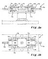
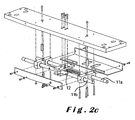
- FIGS 2a-2c illustrate in detail a first means of a device according to the invention, arranged to receive a rim and arrange it in the mounting position of a tire on the rim.
- This first means comprises a first and a second parallel axis notched respectively 11a and 11b coupled by a toothed wheel 12 and arranged under the receiving plane of said rim in the mounting device.
- the axes 11a and 11b are arranged so that the displacement of one in one direction causes that of the other in the opposite direction.
- Each of said axes 11a and 11b is connected via a transmission block, respectively 13a and 13b to a pair of frames respectively 14a and 14b.
- each block 13a, 13b is connected to sixth means, respectively 15a, 15b, which may comprise a hydraulic cylinder or any other means capable of performing the same function, arranged to apply to the block in question a force in the direction of the axis 11a, B that said block connects to the pair of said and opposite directions to move each call in the direction of the axis to which it is connected between a position of engagement of a peripheral edge of the rim by each call and mounting the tire and a release position of said peripheral edge by each call once said tire mounted.
- sixth means respectively 15a, 15b, which may comprise a hydraulic cylinder or any other means capable of performing the same function, arranged to apply to the block in question a force in the direction of the axis 11a, B that said block connects to the pair of said and opposite directions to move each call in the direction of the axis to which it is connected between a position of engagement of a peripheral edge of the rim by each call and mounting the tire and a release position of said peripheral edge by each call once said tire mounted
- the first means arranged for receiving a rim and arranging it in the tire mounting position also comprises a retractable hub 16 under the rim receiving plane, arranged to engage a central orifice of said rim when it is disengaged from its rim. mounting position of the tire once said tire mounted on said rim. Thus, the rim is held in place during the release of the pairs of claws 14a and 14b.
- the first means further comprises two pairs of pins, respectively 17a and 17b retractable under the plane of receiving the rim and arranged to contact the inner edge of the rim to hold it in place when disengaged from its tire mounting position, once said tire is mounted on said rim.
- each pair of lugs 17a and 17b, respectively is coordinated with that of a corresponding pair of lugs, respectively 14a, 14b, a peripheral edge of the rim present in the device being disposed between a pair of lugs and the pair of corresponding claws once a tire mounted on its rim by the device.
- a pair of edges 14a, 14b approaches a peripheral edge of the rim
- the corresponding pair of lugs 17a, 17b deviates and vice versa.
- the rim is held in place by the lugs in question once the tire is mounted and that the pairs of lugs 14a and 14b deviate from the rim, even if it does not include a central hole that can receive the hub. 16.
Landscapes
- Engineering & Computer Science (AREA)
- Mechanical Engineering (AREA)
- Tires In General (AREA)
- Automobile Manufacture Line, Endless Track Vehicle, Trailer (AREA)
- Vehicle Body Suspensions (AREA)
- Testing Of Balance (AREA)
- Automatic Assembly (AREA)
Claims (10)
- Vorrichtung zur Montage eines Reifens auf einer Felge eines Kraftfahrzeugs, umfassend ein erstes Mittel (1), das derart angeordnet ist, dass es die Felge aufnimmt und diese in Position zur Montage des Reifens anordnet, einen Arm (2), dessen erstes Ende mit einem Montagekopf (4) für den Reifen auf der Felge versehen ist, wobei der Kopf (4) drehbar um seine Symmetrieachse angeordnet ist, ein zweites Mittel (3a, 3b, 3c, 3d), das an das zweite Ende des Arms (2) angeschlossen und derart angeordnet ist, dass es dem Arm eine Drehbewegung um die Symmetrieachse der Felge in Montageposition des Reifens verleiht, dadurch gekennzeichnet, dass der Arm (2) auf die Symmetrieachse der Felge in Montageposition des Reifens um einen spitzen Winkel geneigt ist, wobei das erste Ende des Arms (2) somit am weitesten von der Symmetrieachse der Felge in Montageposition des Reifens entfernt ist.
- Vorrichtung nach Anspruch 1, dadurch gekennzeichnet, dass sie ein drittes Mittel (5), das derart angeordnet ist, dass es den Arm (2) orthogonal zur Symmetrieachse der Felge in Montageposition des Reifens verschiebt, und ein viertes Mittel (6) umfasst, das derart angeordnet ist, dass es den Arm (2) parallel zur Symmetrieachse der Felge in Montageposition des Reifens verschiebt.
- Vorrichtung nach einem der Ansprüche 1 - 2, dadurch gekennzeichnet, dass sie ein fünftes Mittel (10) umfasst, das derart angeordnet ist, dass es einen Wulst des auf seiner Felge zu montierenden Reifens in einem bestimmten Winkel ausrichtet.
- Vorrichtung nach einem der Ansprüche 1 - 3, dadurch gekennzeichnet, dass die Drehachse des Montagekopfes (4) des Reifens auf die Symmetrieachse der Felge in Montageposition des Reifens um einen spitzen Winkel geneigt ist.
- Montagevorrichtung nach einem der vorhergehenden Ansprüche 1 - 4, dadurch gekennzeichnet, dass der Montagekopf (4) des Reifens im Wesentlichen die Form eines Kegelstumpfes hat.
- Vorrichtung nach einem der Ansprüche 1 - 4, dadurch gekennzeichnet, dass der Montagekopf (4) des Reifens im Wesentlichen die Form einer kegelstumpfartigen Halbkugel hat.
- Vorrichtung nach einem der Ansprüche 1 - 6, dadurch gekennzeichnet, dass sie eine programmierbare Kontrolleinheit umfasst, die derart angeordnet ist, dass sie Informationen über den Felgentyp und den zu montierenden Reifentyp empfängt und rückwirkend die Position des Arms (2) während der Montage des Reifens auf der Felge durch die Vorrichtung steuert.
- Vorrichtung nach einem der vorhergehenden Ansprüche, dadurch gekennzeichnet, dass das erste Mittel (1), das derart angeordnet ist, dass es die Felge aufnimmt und diese in Montageposition des Reifens anordnet, eine erste (11a) und eine zweite (11b) Zahnachse umfasst, die durch ein Zahnrad (12) gekoppelt und unter der Aufnahmeebene der Felge angeordnet sind, wobei jede der Achsen (11a, 11 b) mit Hilfe eines Übertragungsblocks (13a, 13b) an mindestens eine Spannpratze (14a, 14b) angeschlossen ist, wobei jeder Übertragungsblock (13a, 13b) an sechste Mittel (15a, 15b) angeschlossen ist, die derart angeordnet sind, dass eine Kraft an den Block (13a, 13b) in Richtung der Achse (11a, 11 b), die er an jede Spannpratze (14a, 14b) anschließt, und in entgegen gesetzte Richtungen anlegt, um jede Spannpratze (14a, 14b) zwischen einer Position zum Eingriff eines Umfangsrandes der Felge durch jede Spannpratze (14a, 14b) und zur Montage des Reifens und einer Position zur Freigabe des Umfangsrandes durch jede Spannpratze (14a, 14b) zu verschieben, wenn der Reifen auf der Felge montiert ist.
- Vorrichtung nach Anspruch 8, dadurch gekennzeichnet, dass sie eine Nabe (16) umfasst, die derart angeordnet ist, dass sie in eine Mittelöffnung der Felge eingreift, wenn sie aus ihrer Montageposition des Reifens freigegeben ist, wenn der Reifen auf der Felge montiert ist.
- Vorrichtung nach einem der Ansprüche 8 - 9, dadurch gekennzeichnet, dass sie mindestens zwei Haken (17a, 17b) umfasst, die derart angeordnet sind, dass sie mit dem Innenrand der Felge in Kontakt treten, um sie an Ort und Stelle zu halten, wenn sie aus ihrer Montageposition des Reifens freigegeben wird, wenn der Reifen auf der Felge montiert ist.
Priority Applications (1)
| Application Number | Priority Date | Filing Date | Title |
|---|---|---|---|
| EP03726972A EP1476321B1 (de) | 2001-12-27 | 2003-01-02 | Vorrichtung zum montieren eines reifens an einer fahrzeugfelge |
Applications Claiming Priority (4)
| Application Number | Priority Date | Filing Date | Title |
|---|---|---|---|
| EP01000795 | 2001-12-27 | ||
| EP01000795 | 2001-12-27 | ||
| PCT/BE2003/000001 WO2003055703A1 (fr) | 2001-12-27 | 2003-01-02 | Dispositif de montage d'un pneu sur une jante de vehicule |
| EP03726972A EP1476321B1 (de) | 2001-12-27 | 2003-01-02 | Vorrichtung zum montieren eines reifens an einer fahrzeugfelge |
Publications (2)
| Publication Number | Publication Date |
|---|---|
| EP1476321A1 EP1476321A1 (de) | 2004-11-17 |
| EP1476321B1 true EP1476321B1 (de) | 2007-09-12 |
Family
ID=8176122
Family Applications (1)
| Application Number | Title | Priority Date | Filing Date |
|---|---|---|---|
| EP03726972A Expired - Lifetime EP1476321B1 (de) | 2001-12-27 | 2003-01-02 | Vorrichtung zum montieren eines reifens an einer fahrzeugfelge |
Country Status (6)
| Country | Link |
|---|---|
| US (1) | US20050092443A1 (de) |
| EP (1) | EP1476321B1 (de) |
| AT (1) | ATE372886T1 (de) |
| AU (1) | AU2003201217A1 (de) |
| DE (1) | DE60316257D1 (de) |
| WO (1) | WO2003055703A1 (de) |
Families Citing this family (2)
| Publication number | Priority date | Publication date | Assignee | Title |
|---|---|---|---|---|
| US8973639B2 (en) * | 2011-12-29 | 2015-03-10 | Android Industries Llc | System and method for processing a tire-wheel assembly |
| CN103419581B (zh) * | 2013-04-23 | 2015-09-09 | 台州立马电动车科技有限公司 | 轮胎半自动装配机 |
Family Cites Families (10)
| Publication number | Priority date | Publication date | Assignee | Title |
|---|---|---|---|---|
| US3891019A (en) * | 1973-06-25 | 1975-06-24 | Coats Company Inc | Tire changing apparatus |
| US4034786A (en) * | 1975-11-17 | 1977-07-12 | Royal Industries, Inc. | Wheel chuck |
| US4169585A (en) * | 1978-03-03 | 1979-10-02 | Caterpillar Tractor Co. | Workpiece holder |
| US4800944A (en) * | 1987-02-09 | 1989-01-31 | Allied Automation Systems, Inc. | Single bead tire mounter |
| IT1243660B (it) | 1990-10-22 | 1994-06-16 | Corghi Spa | Macchina smontagomme con autrocentrante reclinabile. |
| US5226465A (en) * | 1991-02-19 | 1993-07-13 | Stahlgruber Otto Gruber Gmbh & Co. | Mounting device for motor vehicle tires |
| US5758703A (en) * | 1995-10-31 | 1998-06-02 | Onodani Machine Co., Ltd. | Apparatus for mounting and removing a tire from a wheel |
| US6125904A (en) * | 1998-06-01 | 2000-10-03 | Aim Automotive Integrated Manufacturing, Inc. | Robotic apparatus and method for assembling a tire to a rim |
| ITVR20020058A1 (it) * | 2002-05-23 | 2003-11-24 | Butler Eng & Marketing | Macchina monta-smontagomme per ruote di veicoli industriali |
| ITVR20020060A1 (it) * | 2002-05-29 | 2003-12-01 | Butler Eng & Marketing | Macchina monta-smontagomme |
-
2003
- 2003-01-02 US US10/500,338 patent/US20050092443A1/en not_active Abandoned
- 2003-01-02 DE DE60316257T patent/DE60316257D1/de not_active Expired - Lifetime
- 2003-01-02 WO PCT/BE2003/000001 patent/WO2003055703A1/fr not_active Ceased
- 2003-01-02 EP EP03726972A patent/EP1476321B1/de not_active Expired - Lifetime
- 2003-01-02 AU AU2003201217A patent/AU2003201217A1/en not_active Abandoned
- 2003-01-02 AT AT03726972T patent/ATE372886T1/de not_active IP Right Cessation
Also Published As
| Publication number | Publication date |
|---|---|
| ATE372886T1 (de) | 2007-09-15 |
| US20050092443A1 (en) | 2005-05-05 |
| WO2003055703A8 (fr) | 2004-09-10 |
| DE60316257D1 (de) | 2007-10-25 |
| WO2003055703A1 (fr) | 2003-07-10 |
| AU2003201217A1 (en) | 2003-07-15 |
| EP1476321A1 (de) | 2004-11-17 |
Similar Documents
| Publication | Publication Date | Title |
|---|---|---|
| EP1385762B1 (de) | Greifer für behälter | |
| EP3822199B1 (de) | Stern für eine rotierende verpackungsmaschine | |
| EP0113419B1 (de) | Verfahren und Einrichtung zum Trennen eines Rohres grossen Durchmessers, insbesondere mit ovalem Querschnitt, wie z.B. ein Gussrohr | |
| FR2771319A1 (fr) | Dispositif de serrage d'un organe tubulaire notamment au moyen de mors mobiles | |
| EP1908590A2 (de) | Transfervorrichtung und Druckmaschine | |
| EP0909667B1 (de) | Hilfsanordnung für das Montieren und Demontieren von Reifen | |
| EP1476321B1 (de) | Vorrichtung zum montieren eines reifens an einer fahrzeugfelge | |
| FR2559264A1 (fr) | Microtome pourvu de moyens de retrait du specimen | |
| EP1775126B1 (de) | Übertragungsvorrichtung von Gegenständen für eine Druckmaschine, Druckmaschine und Übertragungsverfahren | |
| FR2802134A1 (fr) | Machine pour le travail en orbital d'un organe tubulaire | |
| FR2745805A1 (fr) | Machine a derouler des bobines en continu comportant au moins un moyen de deroulage de deux bobines jumelees ou coaxiales simultanement | |
| FR2511500A1 (fr) | Systeme d'alignement de roue et de pneu | |
| EP0437413B1 (de) | Verschiebbare einheitliche Struktur zur Befestigung oder zum Unterstützen von Fahrzeugrädern | |
| FR2848545A1 (fr) | Dispositif de vissage de bouchons | |
| EP0330556B1 (de) | Drehscheibe zum Ausstellen eines Kraftfahrzeuges | |
| EP2896584A2 (de) | Qualitätskontrollanlage einer Reihe von Artikeln, insbesondere von Flaschen | |
| FR2522568A1 (fr) | Machine a meuler le verre | |
| FR2479041A1 (fr) | Installation automatique a poinconner les encoches comprenant un poste supplementaire pour l'usinage de flans | |
| EP0506533B1 (de) | Sägegerät | |
| EP0564360B1 (de) | Offsetdruckmaschine | |
| FR2863934A1 (fr) | Machine d'impression par serigraphie avec dispositif de transfert d'objets a imprimer. | |
| EP2433885A1 (de) | Vorrichtung zur Führung von Artikeln an dem Eingang eines Sternrads | |
| FR2965256A1 (fr) | Dispositif de securite destine a detecter un mauvais positionnement d'un article en entree d'un carrousel. | |
| FR2828846A1 (fr) | Siege a pivotement horizontal d'au moins un demi-tour | |
| FR2527135A1 (fr) | Appareil d'alimentation de rondins |
Legal Events
| Date | Code | Title | Description |
|---|---|---|---|
| PUAI | Public reference made under article 153(3) epc to a published international application that has entered the european phase |
Free format text: ORIGINAL CODE: 0009012 |
|
| 17P | Request for examination filed |
Effective date: 20040726 |
|
| AK | Designated contracting states |
Kind code of ref document: A1 Designated state(s): AT BE BG CH CY CZ DE DK EE ES FI FR GB GR HU IE IT LI LU MC NL PT SE SI SK TR |
|
| AX | Request for extension of the european patent |
Extension state: AL LT LV MK RO |
|
| GRAP | Despatch of communication of intention to grant a patent |
Free format text: ORIGINAL CODE: EPIDOSNIGR1 |
|
| GRAS | Grant fee paid |
Free format text: ORIGINAL CODE: EPIDOSNIGR3 |
|
| GRAA | (expected) grant |
Free format text: ORIGINAL CODE: 0009210 |
|
| AK | Designated contracting states |
Kind code of ref document: B1 Designated state(s): AT BE BG CH CY CZ DE DK EE ES FI FR GB GR HU IE IT LI LU MC NL PT SE SI SK TR |
|
| REG | Reference to a national code |
Ref country code: GB Ref legal event code: FG4D Free format text: NOT ENGLISH |
|
| REG | Reference to a national code |
Ref country code: CH Ref legal event code: EP |
|
| REF | Corresponds to: |
Ref document number: 60316257 Country of ref document: DE Date of ref document: 20071025 Kind code of ref document: P |
|
| REG | Reference to a national code |
Ref country code: IE Ref legal event code: FG4D Free format text: LANGUAGE OF EP DOCUMENT: FRENCH |
|
| PG25 | Lapsed in a contracting state [announced via postgrant information from national office to epo] |
Ref country code: FI Free format text: LAPSE BECAUSE OF FAILURE TO SUBMIT A TRANSLATION OF THE DESCRIPTION OR TO PAY THE FEE WITHIN THE PRESCRIBED TIME-LIMIT Effective date: 20070912 |
|
| PG25 | Lapsed in a contracting state [announced via postgrant information from national office to epo] |
Ref country code: AT Free format text: LAPSE BECAUSE OF FAILURE TO SUBMIT A TRANSLATION OF THE DESCRIPTION OR TO PAY THE FEE WITHIN THE PRESCRIBED TIME-LIMIT Effective date: 20070912 |
|
| NLV1 | Nl: lapsed or annulled due to failure to fulfill the requirements of art. 29p and 29m of the patents act | ||
| GBV | Gb: ep patent (uk) treated as always having been void in accordance with gb section 77(7)/1977 [no translation filed] | ||
| PG25 | Lapsed in a contracting state [announced via postgrant information from national office to epo] |
Ref country code: ES Free format text: LAPSE BECAUSE OF FAILURE TO SUBMIT A TRANSLATION OF THE DESCRIPTION OR TO PAY THE FEE WITHIN THE PRESCRIBED TIME-LIMIT Effective date: 20071223 Ref country code: GR Free format text: LAPSE BECAUSE OF FAILURE TO SUBMIT A TRANSLATION OF THE DESCRIPTION OR TO PAY THE FEE WITHIN THE PRESCRIBED TIME-LIMIT Effective date: 20071213 Ref country code: NL Free format text: LAPSE BECAUSE OF FAILURE TO SUBMIT A TRANSLATION OF THE DESCRIPTION OR TO PAY THE FEE WITHIN THE PRESCRIBED TIME-LIMIT Effective date: 20070912 |
|
| REG | Reference to a national code |
Ref country code: IE Ref legal event code: FD4D |
|
| PG25 | Lapsed in a contracting state [announced via postgrant information from national office to epo] |
Ref country code: SK Free format text: LAPSE BECAUSE OF FAILURE TO SUBMIT A TRANSLATION OF THE DESCRIPTION OR TO PAY THE FEE WITHIN THE PRESCRIBED TIME-LIMIT Effective date: 20070912 Ref country code: GB Free format text: LAPSE BECAUSE OF FAILURE TO SUBMIT A TRANSLATION OF THE DESCRIPTION OR TO PAY THE FEE WITHIN THE PRESCRIBED TIME-LIMIT Effective date: 20070912 Ref country code: CZ Free format text: LAPSE BECAUSE OF FAILURE TO SUBMIT A TRANSLATION OF THE DESCRIPTION OR TO PAY THE FEE WITHIN THE PRESCRIBED TIME-LIMIT Effective date: 20070912 Ref country code: PT Free format text: LAPSE BECAUSE OF FAILURE TO SUBMIT A TRANSLATION OF THE DESCRIPTION OR TO PAY THE FEE WITHIN THE PRESCRIBED TIME-LIMIT Effective date: 20080212 |
|
| PG25 | Lapsed in a contracting state [announced via postgrant information from national office to epo] |
Ref country code: SE Free format text: LAPSE BECAUSE OF FAILURE TO SUBMIT A TRANSLATION OF THE DESCRIPTION OR TO PAY THE FEE WITHIN THE PRESCRIBED TIME-LIMIT Effective date: 20071212 |
|
| PLBE | No opposition filed within time limit |
Free format text: ORIGINAL CODE: 0009261 |
|
| STAA | Information on the status of an ep patent application or granted ep patent |
Free format text: STATUS: NO OPPOSITION FILED WITHIN TIME LIMIT |
|
| PG25 | Lapsed in a contracting state [announced via postgrant information from national office to epo] |
Ref country code: DK Free format text: LAPSE BECAUSE OF FAILURE TO SUBMIT A TRANSLATION OF THE DESCRIPTION OR TO PAY THE FEE WITHIN THE PRESCRIBED TIME-LIMIT Effective date: 20070912 Ref country code: DE Free format text: LAPSE BECAUSE OF FAILURE TO SUBMIT A TRANSLATION OF THE DESCRIPTION OR TO PAY THE FEE WITHIN THE PRESCRIBED TIME-LIMIT Effective date: 20071213 |
|
| 26N | No opposition filed |
Effective date: 20080613 |
|
| PG25 | Lapsed in a contracting state [announced via postgrant information from national office to epo] |
Ref country code: MC Free format text: LAPSE BECAUSE OF NON-PAYMENT OF DUE FEES Effective date: 20080131 |
|
| REG | Reference to a national code |
Ref country code: CH Ref legal event code: PL |
|
| PG25 | Lapsed in a contracting state [announced via postgrant information from national office to epo] |
Ref country code: IE Free format text: LAPSE BECAUSE OF FAILURE TO SUBMIT A TRANSLATION OF THE DESCRIPTION OR TO PAY THE FEE WITHIN THE PRESCRIBED TIME-LIMIT Effective date: 20070912 Ref country code: CH Free format text: LAPSE BECAUSE OF NON-PAYMENT OF DUE FEES Effective date: 20080131 Ref country code: LI Free format text: LAPSE BECAUSE OF NON-PAYMENT OF DUE FEES Effective date: 20080131 |
|
| REG | Reference to a national code |
Ref country code: FR Ref legal event code: ST Effective date: 20081029 |
|
| PG25 | Lapsed in a contracting state [announced via postgrant information from national office to epo] |
Ref country code: EE Free format text: LAPSE BECAUSE OF FAILURE TO SUBMIT A TRANSLATION OF THE DESCRIPTION OR TO PAY THE FEE WITHIN THE PRESCRIBED TIME-LIMIT Effective date: 20070912 |
|
| PGFP | Annual fee paid to national office [announced via postgrant information from national office to epo] |
Ref country code: BE Payment date: 20080801 Year of fee payment: 6 |
|
| PG25 | Lapsed in a contracting state [announced via postgrant information from national office to epo] |
Ref country code: FR Free format text: LAPSE BECAUSE OF NON-PAYMENT OF DUE FEES Effective date: 20080131 |
|
| PG25 | Lapsed in a contracting state [announced via postgrant information from national office to epo] |
Ref country code: SI Free format text: LAPSE BECAUSE OF FAILURE TO SUBMIT A TRANSLATION OF THE DESCRIPTION OR TO PAY THE FEE WITHIN THE PRESCRIBED TIME-LIMIT Effective date: 20070912 |
|
| PG25 | Lapsed in a contracting state [announced via postgrant information from national office to epo] |
Ref country code: CY Free format text: LAPSE BECAUSE OF FAILURE TO SUBMIT A TRANSLATION OF THE DESCRIPTION OR TO PAY THE FEE WITHIN THE PRESCRIBED TIME-LIMIT Effective date: 20070912 |
|
| PG25 | Lapsed in a contracting state [announced via postgrant information from national office to epo] |
Ref country code: BG Free format text: LAPSE BECAUSE OF FAILURE TO SUBMIT A TRANSLATION OF THE DESCRIPTION OR TO PAY THE FEE WITHIN THE PRESCRIBED TIME-LIMIT Effective date: 20071212 |
|
| PG25 | Lapsed in a contracting state [announced via postgrant information from national office to epo] |
Ref country code: BE Free format text: LAPSE BECAUSE OF NON-PAYMENT OF DUE FEES Effective date: 20090131 |
|
| PG25 | Lapsed in a contracting state [announced via postgrant information from national office to epo] |
Ref country code: LU Free format text: LAPSE BECAUSE OF NON-PAYMENT OF DUE FEES Effective date: 20080102 Ref country code: HU Free format text: LAPSE BECAUSE OF FAILURE TO SUBMIT A TRANSLATION OF THE DESCRIPTION OR TO PAY THE FEE WITHIN THE PRESCRIBED TIME-LIMIT Effective date: 20080313 |
|
| PG25 | Lapsed in a contracting state [announced via postgrant information from national office to epo] |
Ref country code: TR Free format text: LAPSE BECAUSE OF FAILURE TO SUBMIT A TRANSLATION OF THE DESCRIPTION OR TO PAY THE FEE WITHIN THE PRESCRIBED TIME-LIMIT Effective date: 20070912 |
|
| PG25 | Lapsed in a contracting state [announced via postgrant information from national office to epo] |
Ref country code: IT Free format text: LAPSE BECAUSE OF NON-PAYMENT OF DUE FEES Effective date: 20080131 |