EP0146273A2 - Piezoelektrische Koaxialkabel - Google Patents
Piezoelektrische Koaxialkabel Download PDFInfo
- Publication number
- EP0146273A2 EP0146273A2 EP84308050A EP84308050A EP0146273A2 EP 0146273 A2 EP0146273 A2 EP 0146273A2 EP 84308050 A EP84308050 A EP 84308050A EP 84308050 A EP84308050 A EP 84308050A EP 0146273 A2 EP0146273 A2 EP 0146273A2
- Authority
- EP
- European Patent Office
- Prior art keywords
- wire
- intermediate layer
- stretching
- piezoelectric
- cable
- Prior art date
- Legal status (The legal status is an assumption and is not a legal conclusion. Google has not performed a legal analysis and makes no representation as to the accuracy of the status listed.)
- Granted
Links
- 239000004020 conductor Substances 0.000 claims abstract description 88
- 229920000642 polymer Polymers 0.000 claims abstract description 20
- 230000008018 melting Effects 0.000 claims abstract description 18
- 238000002844 melting Methods 0.000 claims abstract description 18
- 229910052751 metal Inorganic materials 0.000 claims description 28
- 239000002184 metal Substances 0.000 claims description 28
- 238000000034 method Methods 0.000 claims description 28
- KRHYYFGTRYWZRS-UHFFFAOYSA-M Fluoride anion Chemical compound [F-] KRHYYFGTRYWZRS-UHFFFAOYSA-M 0.000 claims description 20
- 239000000463 material Substances 0.000 claims description 16
- 238000010438 heat treatment Methods 0.000 claims description 14
- 238000001816 cooling Methods 0.000 claims description 7
- 238000010924 continuous production Methods 0.000 claims description 5
- 239000000155 melt Substances 0.000 claims description 2
- BQCIDUSAKPWEOX-UHFFFAOYSA-N 1,1-Difluoroethene Chemical compound FC(F)=C BQCIDUSAKPWEOX-UHFFFAOYSA-N 0.000 abstract description 2
- 229910001092 metal group alloy Inorganic materials 0.000 abstract description 2
- 238000010276 construction Methods 0.000 abstract 1
- 229910045601 alloy Inorganic materials 0.000 description 9
- 239000000956 alloy Substances 0.000 description 9
- 230000015572 biosynthetic process Effects 0.000 description 6
- 229920001577 copolymer Polymers 0.000 description 5
- PEDCQBHIVMGVHV-UHFFFAOYSA-N Glycerine Chemical compound OCC(O)CO PEDCQBHIVMGVHV-UHFFFAOYSA-N 0.000 description 4
- BQCADISMDOOEFD-UHFFFAOYSA-N Silver Chemical compound [Ag] BQCADISMDOOEFD-UHFFFAOYSA-N 0.000 description 4
- 230000002706 hydrostatic effect Effects 0.000 description 4
- 229910052709 silver Inorganic materials 0.000 description 4
- 239000004332 silver Substances 0.000 description 4
- 230000007423 decrease Effects 0.000 description 3
- 230000000694 effects Effects 0.000 description 3
- 210000003739 neck Anatomy 0.000 description 3
- 239000003973 paint Substances 0.000 description 3
- 239000004677 Nylon Substances 0.000 description 2
- 238000006243 chemical reaction Methods 0.000 description 2
- 230000005684 electric field Effects 0.000 description 2
- 238000001125 extrusion Methods 0.000 description 2
- 235000011187 glycerol Nutrition 0.000 description 2
- 239000007788 liquid Substances 0.000 description 2
- 150000002739 metals Chemical class 0.000 description 2
- 239000000203 mixture Substances 0.000 description 2
- 229920001778 nylon Polymers 0.000 description 2
- 230000035945 sensitivity Effects 0.000 description 2
- 238000004544 sputter deposition Methods 0.000 description 2
- 239000011800 void material Substances 0.000 description 2
- KIKGHMPIMPPLCQ-UHFFFAOYSA-N 1,6-dichloro-3,3,4,4,5,6,6-heptafluorohex-1-ene Chemical compound FC(C(F)(F)Cl)C(C(C=CCl)(F)F)(F)F KIKGHMPIMPPLCQ-UHFFFAOYSA-N 0.000 description 1
- RYGMFSIKBFXOCR-UHFFFAOYSA-N Copper Chemical compound [Cu] RYGMFSIKBFXOCR-UHFFFAOYSA-N 0.000 description 1
- XFXPMWWXUTWYJX-UHFFFAOYSA-N Cyanide Chemical compound N#[C-] XFXPMWWXUTWYJX-UHFFFAOYSA-N 0.000 description 1
- 239000002033 PVDF binder Substances 0.000 description 1
- 229920000331 Polyhydroxybutyrate Polymers 0.000 description 1
- 239000004411 aluminium Substances 0.000 description 1
- 229910052782 aluminium Inorganic materials 0.000 description 1
- XAGFODPZIPBFFR-UHFFFAOYSA-N aluminium Chemical compound [Al] XAGFODPZIPBFFR-UHFFFAOYSA-N 0.000 description 1
- 229910052797 bismuth Inorganic materials 0.000 description 1
- JCXGWMGPZLAOME-UHFFFAOYSA-N bismuth atom Chemical compound [Bi] JCXGWMGPZLAOME-UHFFFAOYSA-N 0.000 description 1
- 230000015556 catabolic process Effects 0.000 description 1
- 239000003795 chemical substances by application Substances 0.000 description 1
- UUAGAQFQZIEFAH-UHFFFAOYSA-N chlorotrifluoroethylene Chemical group FC(F)=C(F)Cl UUAGAQFQZIEFAH-UHFFFAOYSA-N 0.000 description 1
- 230000008602 contraction Effects 0.000 description 1
- 229910052802 copper Inorganic materials 0.000 description 1
- 239000010949 copper Substances 0.000 description 1
- 230000003247 decreasing effect Effects 0.000 description 1
- 230000000593 degrading effect Effects 0.000 description 1
- 238000000151 deposition Methods 0.000 description 1
- 239000006023 eutectic alloy Substances 0.000 description 1
- 230000005496 eutectics Effects 0.000 description 1
- 230000008020 evaporation Effects 0.000 description 1
- 238000001704 evaporation Methods 0.000 description 1
- XUCNUKMRBVNAPB-UHFFFAOYSA-N fluoroethene Chemical compound FC=C XUCNUKMRBVNAPB-UHFFFAOYSA-N 0.000 description 1
- 230000006698 induction Effects 0.000 description 1
- 238000003780 insertion Methods 0.000 description 1
- 230000037431 insertion Effects 0.000 description 1
- 238000010884 ion-beam technique Methods 0.000 description 1
- 238000004519 manufacturing process Methods 0.000 description 1
- 238000010422 painting Methods 0.000 description 1
- 239000008188 pellet Substances 0.000 description 1
- 230000002093 peripheral effect Effects 0.000 description 1
- 238000010587 phase diagram Methods 0.000 description 1
- 238000007747 plating Methods 0.000 description 1
- 230000010287 polarization Effects 0.000 description 1
- 239000005015 poly(hydroxybutyrate) Substances 0.000 description 1
- 229920003229 poly(methyl methacrylate) Polymers 0.000 description 1
- -1 polyethylene, ethylene vinyl acetate copolymers Polymers 0.000 description 1
- 239000002861 polymer material Substances 0.000 description 1
- 239000004926 polymethyl methacrylate Substances 0.000 description 1
- 229920002981 polyvinylidene fluoride Polymers 0.000 description 1
- 230000005855 radiation Effects 0.000 description 1
- 238000000926 separation method Methods 0.000 description 1
- 238000005507 spraying Methods 0.000 description 1
- 229920001897 terpolymer Polymers 0.000 description 1
Images

Classifications
-
- H—ELECTRICITY
- H10—SEMICONDUCTOR DEVICES; ELECTRIC SOLID-STATE DEVICES NOT OTHERWISE PROVIDED FOR
- H10N—ELECTRIC SOLID-STATE DEVICES NOT OTHERWISE PROVIDED FOR
- H10N30/00—Piezoelectric or electrostrictive devices
- H10N30/60—Piezoelectric or electrostrictive devices having a coaxial cable structure
-
- H—ELECTRICITY
- H10—SEMICONDUCTOR DEVICES; ELECTRIC SOLID-STATE DEVICES NOT OTHERWISE PROVIDED FOR
- H10N—ELECTRIC SOLID-STATE DEVICES NOT OTHERWISE PROVIDED FOR
- H10N30/00—Piezoelectric or electrostrictive devices
- H10N30/01—Manufacture or treatment
- H10N30/04—Treatments to modify a piezoelectric or electrostrictive property, e.g. polarisation characteristics, vibration characteristics or mode tuning
- H10N30/045—Treatments to modify a piezoelectric or electrostrictive property, e.g. polarisation characteristics, vibration characteristics or mode tuning by polarising
-
- H—ELECTRICITY
- H10—SEMICONDUCTOR DEVICES; ELECTRIC SOLID-STATE DEVICES NOT OTHERWISE PROVIDED FOR
- H10N—ELECTRIC SOLID-STATE DEVICES NOT OTHERWISE PROVIDED FOR
- H10N30/00—Piezoelectric or electrostrictive devices
- H10N30/01—Manufacture or treatment
- H10N30/09—Forming piezoelectric or electrostrictive materials
- H10N30/098—Forming organic materials
-
- Y—GENERAL TAGGING OF NEW TECHNOLOGICAL DEVELOPMENTS; GENERAL TAGGING OF CROSS-SECTIONAL TECHNOLOGIES SPANNING OVER SEVERAL SECTIONS OF THE IPC; TECHNICAL SUBJECTS COVERED BY FORMER USPC CROSS-REFERENCE ART COLLECTIONS [XRACs] AND DIGESTS
- Y10—TECHNICAL SUBJECTS COVERED BY FORMER USPC
- Y10S—TECHNICAL SUBJECTS COVERED BY FORMER USPC CROSS-REFERENCE ART COLLECTIONS [XRACs] AND DIGESTS
- Y10S310/00—Electrical generator or motor structure
- Y10S310/80—Piezoelectric polymers, e.g. PVDF
-
- Y—GENERAL TAGGING OF NEW TECHNOLOGICAL DEVELOPMENTS; GENERAL TAGGING OF CROSS-SECTIONAL TECHNOLOGIES SPANNING OVER SEVERAL SECTIONS OF THE IPC; TECHNICAL SUBJECTS COVERED BY FORMER USPC CROSS-REFERENCE ART COLLECTIONS [XRACs] AND DIGESTS
- Y10—TECHNICAL SUBJECTS COVERED BY FORMER USPC
- Y10T—TECHNICAL SUBJECTS COVERED BY FORMER US CLASSIFICATION
- Y10T29/00—Metal working
- Y10T29/42—Piezoelectric device making
Definitions
- piezoelectric coaxial cables have hitherto been proposed. Such cables comprise a central electrical conductor, an intermediate insulating layer of piezoelectric material surrounding the central conductor, and an outer electrical conductor surrounding the intermediate layer. Piezoelectric coaxial cables have often been proposed for use as transducers since, when they are subjected to an applied pressure, for example caused by impact by an object or acoustic pressure changes, a potential difference will be generated between the electrodes by the piezoelectric material.
- Electric field gradients of from 5 to 200 MVm are typical for the polarizing operation, the maximum applied field gradient usually being determined by dielectric break-down of the polymer material.
- the electrodes used for the polarizing operation may be metal layers that have been deposited after the material has been stretched or, if the sheet is stretched in the nip of a pair of rollers, the rollers themselves may be used as the electrodes.
- corona discharge electrodes may be used on one or both sides of the sheet, for example as described in U.S. Patent Specification No. 4,308,370.
- the intermediate layer In the case of a piezoelectric coaxial cable, in order to maximize its piezoelectric response, the intermediate layer would need to be stretched axially and polarized radially between an inner, central, electrode and an outer electrode. While the outer electrode may be applied to the intermediate layer after stretching, or, if a corona poling method is employed, the cable may be passed through a corona discharge electrode and an outer electrical conductor for the cable be subsequently provided, significant problems are encountered in the provision of an internal electrode or conductor for the cable: it is not possible to extrude the intermediate layer onto a conventional metal conductor, e.g. a copper conductor, in that it would then be difficult subsequently to stretch the intermediate layer in order to convert it into form I.
- a conventional metal conductor e.g. a copper conductor
- the invention provides a , piezoelectric coaxial cable, which comprises a central electrical conductor, an outer electrical conductor and an intermediate piezoelectric layer, the central conductor and the intermediate layer having been axially stretched and the intermediate layer having been radially polarized to render it piezoelectric, and the intermediate layer having an internal radius that is not more than 0.5 times its external radius.
- the internal radius of the intermediate layer is not more than 0.4 times, more preferably not more than 0.35 times the external radius thereof. Most preferably the internal radius of the intermediate layer is about 0.33 times its external radius although it is possible for the internal radius to be smaller, e.g. less than 0.3 times its external radius.
- the ratio of the internal radius to the external radius of the intermediate layer does not change significantly when the conductor and the intermediate layer are stretched, provided that they lie in the above range, so that the above ratios are also preferred for the intermediate layer radii before stretching.
- the cable according to the invention may have an intermediate layer of wall thickness of at least 0.2mm, preferably at least 0.3mm, more preferably at least 0.4mm, and especially at least 0.5mm, which allows the ,piezoelectric sensitivity of the cable to be increased.
- the maximum wall thickness of the intermediate layer and the maximum value of the ratio R of the internal radius of the intermediate layer to the external radius of the intermediate layer depend on one another and also depend on the temperature at which the intermediate layer is stretched.
- the maximum wall thickness of the intermediate layer that can be obtained without the formation of voids or breaks in the central conductor decreases as the ratio R of the internal radius to the external radius of the intermediate layer increases, for any given stretching temperature. Also, the maximum wall thickness increases for any given ratio R as the stretching temperature increases.
- the piezoelectric response of the resulting cable will suffer if the stretching and/or poling temperature is raised to too high a level, due to poor form II to form I conversion of the polymer forming the intermediate layer and/or due to thermal depoling of the polymer following the poling step. For this reason it is preferred to stretch the wire at temperatures not more than 140°C and especially not more than 130°C. At these temperatures it has been found that voiding of the central conductor can be prevented if the ratio R of the internal radius to the external radius of the intermediate layer (after stretching) satisfies the empirical inequality: or where T is the wall thickness of the intermediate layer after stretching, measured in millimetres.
- the ratio R and thicknes T preferably satisfy the inequality: or
- the internal radius of the intermediate layer While it is preferred for the internal radius of the intermediate layer to be as small as possible with respect to its external radius, for practical reasons the internal radius is usually not less than 0.1 times, e.g. not less than 0.2 times the external radius thereof. Accordingly the preferred coaxial cables according to the invention will have an internal conductor radius of from 0.2 to 0.45 times the external radius of the intermediate layer and an intermediate layer wall thickness of from 0.4 to 0.8mm.
- the cable is described herein as a "coaxial cable", this term is not intended to imply that the central conductor and the outer conductor must be exactly concentric, but rather it is intended to mean that the central conductor is surrounded by, and insulated from, the outer conductor by the intermediate layer. It will be appreciated by those skilled in the art that some deviation from absolute concentricity is the rule in coaxial cables, and in some cases this may be intended.
- the intermediate layer may be formed from any material that can be rendered piezoelectric by orientation and polarizing.
- materials include nylon 5, nylon 7, polyhydroxybutyrate, vinylidine cyanide/vinyl acetate copolymers and vinylidine fluoride polymers.
- the term "vinylidine fluoride polymer” is intended to include polyvinylidine fluoride, commonly abbreviated to "PVDF” or "PVF 2 " and those copolymers of vinylidine fluoride in which a piezoelectric activity may be generated or enhanced by orientation and polarizing.
- Suitable copolymers include copolymers and terpolymers of vinylidine fluoride with vinyl fluoride, trifluoroethylene, tetrafluoroethylene, vinyl chloride, and chlorotrifluoroethylene.
- blends of vinylidine fluoride polymers with other polymers, e.g. polymethylmethacrylate, are included provided that the piezoelectric activity thereof is not destroyed.
- the intermediate layer comprises a vinylidine fluoride polymer, more preferably polyvinylidine fluoride and especially it consists substantially solely of polyvinylidine fluoride.
- the central conductor comprises a low melting point metal so that the central conductor and the intermediate layer can be heated to melt the metal and then stretched while the metal is still liquid.
- a low melting point metal any metal having a melting point that is sufficiently low to allow the metal to melt without thermally degrading or melting the intermediate layer may be used, and in some cases, for reasons discussed below, it is desirable to select a metal having as high a melting point as possible having regard to the softening point of the intermediate layer and having regard to the preferred stretching temperature.
- the metal has a melting point of not more than 170°C, more preferably not more than 160°C and ,especially not more than 150°C.
- the metal may have a melting point of at least 50°C, more preferably at least 60°C, especially at least 65°C and most especially at least 70°C.
- the metal forming the central conductor may be formed from an alloy having a eutectic composition in which case it will exhibit a single, well defined, melting point, or it may be formed from a non-eutectic alloy, in which case the metal may enter a phase between the solidus and liquidus lines of its phase diagram in which its ductility increases with temperature. It is not necessary for the metal to melt completely for the stretching operation, provided that it becomes sufficiently ductile that it will not fracture.
- the invention provides a method of forming a piezoelectric cable, which comprises the steps of :
- the dimensions of the resulting cable are preferably as described above. Since the absolute value of the wall thickness of the cable decreases as the conductor and intermediate layer are stretched, the intermediate layer preferably has a wall thickness prior to stretching of at least 0.3, more preferably at least 0.5, especially at least 0.8 and most especially at least 1.0mm.
- the preferred materials for forming the insulating layer and the central conductor are those described above.
- the wire should be heated to an elevated temper- , ature before it is stretched in order to melt the central conductor, if a low melting point metal is used, and to raise the insulating layer to a suitable stretching temperature, e.g. a temperature in the range of from 50 to 170°C, preferably from 60 to 150°C and especially from 80 to 130°C.
- a suitable stretching temperature e.g. a temperature in the range of from 50 to 170°C, preferably from 60 to 150°C and especially from 80 to 130°C.
- the ratio R of the internal radius of the intermediate layer to its external radius preferably satisfies the inequality: where T is the wall thickness of the intermediate layer prior to stretching, measured in millimetres.
- the wire may be heated in any of a number of ways. For example it may be heated by means of a hot-air gun or it may be passed through an oven which may itself be heated by an electric resistance heater or by gas. Other methods of heating the wire which may be used in combination with one another include the use of a microwave heating source, induction heating coil, infrared radiation source, a hot liquid bath e.g. a glycerine bath, or electric resistance heating of the central conductor. The particular method of heating the wire will depend on a number of factors including the desired stretching temperature (which will itself depend on the required piezoelectric sensitivity of the cable) and the choice of material used as the central conductor.
- the process may be conducted so that the inner portion of the insulating layer is at a higher temperature than the outer portion thereof. Not only does such a temperature difference across the insulating layer allow the use of somewhat higher melting point metals without the polymer temperature being too high for effective conversion to form I, but also it is currently believed that this may assist the radial contraction of the insulating layer when the wire is stretched, thereby reducing the possibility of void formation within the central conductor or between the central conductor and the insulating layer. This may conveniently be achieved either by allowing the wire to cool for a number of seconds after it has been heated, or by first heating the wire e.g. by a microwave source or in a heating bath or hot air zone followed by a short period of forced cooling.
- the wire is stretched to the "natural" draw ratio of the insulating layer if such a ratio exists, for example about 3.5 to 4.5 times its original length in the case of a vinylidine fluoride polymer, although it is possible to stretch the wire to a lesser or greater extent if desired.
- the stretched wire may be provided with an outer electrical conductor either before or after the insulating layer has been polarized.
- the wire may be stretched, provided with a deposited metal outer conductor and then polarized by application of a high D.C. potential to the inner and outer conductors.
- the outer electrical conductor is provided after the insulating layer has been polarized, in which case the insulating layer is preferably polarized by means of a corona discharge; the wire being passed through an annular corona discharge electrode while the other electrode for the polarizing operation is provided by the central conductor.
- the stretching step (b) and the polarizing step (c) are conducted substantially simultaneously, that is to say, so that at least part of the polarizing step coincides with at least part of the stretching step. It is not necessary for both steps to have the same duration: it may be desirable for polarization (commonly referred to as "poling") to carry on after stretching has been completed.
- step (b) and the polarizing step (c) are conducted as a continuous process in which wire formed in step (a) of indefinite length is passed through a heating zone in which the wire is heated to a predetermined elevated temperature, and the heated wire is passed through a stretching zone and a polarizing zone and then through a cooling zone, such that, at any instant, only a portion of the wire is at or above the predetermined elevated temperature.
- the invention provides a method of forming a piezoelectric cable, which comprises the steps of :
- the stretching zone and the polarizing zone may occur at different positions along the path of the wire so that it is stretched and poled sequentially, or they may occur in the same position so that stretching and polarizing occur simultaneously.
- polyvinylidine fluoride is stretched to its natural draw ratio in a continuous process, it is observed to "neck" at a certain point, that is to say, the lateral dimensions abruptly decrease at a particular point as it is stretched. It is preferred for the wire to be polarized at the point at which it necks.
- Another advantage of the invention is that it enables a piezoelectric coaxial cable to be formed in which the intermediate piezoelectric layer is substantially free of voids.
- the wire is formed in step (a) by co-extruding the central conductor and the insulating layer so that long lengths of wire may be formed.
- the stretching and polarizing steps may be conducted immediately after the wire has been formed or it may be spooled and stored before stretching and polarizing.
- the outer electrical conductor may be provided by a number of means in known manner. For example it may be painted on using a metal paint or a metal may be deposited by an electroless deposition method, for example as described in U.S. Patent No. 4,180,602, the disclosure of which is incorporated herein by reference. Other methods include evaporation, sputtering techniques, or ion beam plating. Alternatively the outer electrode may be provided as a braid in known manner. Combinations of these forms of conductor are also possible.
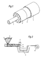
- a piezoelectric coaxial cable comprises a central conductor 1 formed from one of the alloys shown in table I, an intermediate insulating layer 2 formed from polyvinylidine fluoride and an outer conductive layer 3 formed from silver paint.
- the radius of the central conductor, and therefore the internal radius of the insulating layer is 0.3 times the external radius of the insulating layer.
- the cable may optionally be provided as shown with a polymeric jacket 4, for example formed from polyvinylidine fluoride, polyethylene, ethylene vinyl acetate copolymers and the like.
- Figures 2 and 3 show schematically the formation of the wire and then stretching and polarizing it.
- Polyvinylidine fluoride pellets 5 and low melting point metal alloy 6 are fed into an extruder fitted with a co-extrusion die 7.
- the die 7 is designed so that the internal and external radii of the polyvinylidine fluoride layer will have the appropriate ratio.
- the wire 8 is formed it is passed through a cooling bath 9 and quenched to ambient temperature and is then wound onto a take-up spool 10. The leading end of the wire 8 is kept accessible as the wire is wound onto the spool 10.
- the spool 10 is then used as a feed spool in the next stage of the process shown in figure 3.
- the wire is taken off spool 10, passed through feed rollers 11, heating zone 12, cooling zone 13, temperature controlled polarizing zone 14, traction rollers 15 and heating zone 12, cooling zone 13, temperature controlled polarizing zone 14, traction rollers 15 and then to take-up spool 16.
- the central conductor 1 is electrically connected to both the spool 10 and the spool 16 which are earthed.
- the traction rollers 15 are adjusted so that their peripheral speed is four times that of the feed rollers 11, thereby causing the wire 4 to stretch by 4:1 as it passes between them.
- the wire As the wire leaves the feed rollers 11 it passes through a heating zone 12 in the form of a glycerine bath which heats the wire to a uniform temperature in the range of from 100 to 170°C depending on the metal used for the central conductor.
- the heated wire passes through a cooling zone 13 in which it is briefly cooled by cold air to reduce the temperature of the external surface of the wire by about 20 to 50°C, and then, optionally via pinch rollers (not shown), through the polarizing zone 14 in which it is subjected to a corona discharge of up to about 40 kV.
- the polarizing zone is so located, and its temperature is so adjusted, that the wire necks down at this stage.
- the wire 4 After having been polarized, the wire 4 passes through the traction rollers 15 which are maintained at ambient temperature and so cool the wire, and the wire is then taken up by the take-up spool 16.
- the wire is ready to have an outer conductor deposited thereon in known manner.
- an aluminium layer of about 50 to 60 nanometres thickness may be deposited by sputtering, or a silver layer of 25 micrometres typical thickness may be applied by painting or spraying.
- a sample of piezoelectric cable was formed by co-extruding a central conductor formed from alloy No. 4 in Table I and polyvinylidine fluoride so that the central conductor radius and the polymer insulating layer internal radius (a ) was 0.48mm and the insulating layer external radius (b ) was 1.5mm.
- the wire was stretched at a mean temperature of about 120°C to a draw ratio of 4:1 and was simultaneously poled by a corona discharge having a 35 kV potential difference.
- the resulting wire was provided with a silver outer electrode using silver paint sold under the trademark "Electrodag".
- the internal radius of the stretched insulating layer (a ) was 0.24mm and its external radius (b ) was 0.75mm giving a wall thickness of 0.51mm and a ratio a /b of 0.32.
- the value (a u /a s ) 2 is equal to 4 and so is equal to the draw ratio, indicating that the total internal volume enclosed by the intermediate layer did not increase on stretching.
- the cable could be formed continuously in long lengths and exhibited a piezoelectric coefficient in the 1 direction (d 31 ) of 25 pCN 1 and a hydrostatic piezoelectric coefficient (d 3h ) of 8-10 pCN -1 .
- Example 1 was repeated with the exception that alloy No. 6 of table I was used for the central electrode and the dimensions were as shown in table II below.
- the cable had a hydrostatic piezoelectric coefficient (d 3h ) of 11-14 pCN and a d 31 coefficient of 35 pCN -1 .
- Example 2 was repeated with the exception that the size of the central conductor and the intermediate insulating layer were adjusted to give a relatively low value for the ratio of the internal radius of the insulating layer (a) to its external radius (b).
- the dimensions are shown in Table II.
- Example 1 was repeated with the exception that alloy No. 6 of table I was used as the central conductor, the mean stretching temperature was 125°C and the dimensions were as shown in Table II.
- Example 4 was repeated with the exception that, as shown in Table I, the wall thickness was relatively high (1.48mm before stretching and 0.79mm after stretching) and a relatively low ratio R (0.23 to 0.25).
- This cable exhibited a few breaks in its central conductor but the breaks were spaced apart by lengths of continuous conductor so tht the cable could be cut and used in discrete lengths.
- Example 4 was repeated with the exception that the cable had a ratio R before stretching of 0.5 and after stretching of 0.54 and that the initial wall thickness of the intermediate layer was 0.78mm which reduced to 0.38mm after stretching. Considerable breaking and voiding of the central conductor was observed.
- Example 1 was repeated with the exception that the wire formed from the central conductor and the intermediate layer was stretched between the jaws of an "Instron” (trademark) tensometer instead of being stretched by the preferred continuous process according to the invention and that alloy No. 1 of Table I was used as the central conductor. The dimensions are shown in table II.
- Table III shows the value of R s - (0.67-0.55T) which will be zero or negative if the inequality I above is satisfied, and also shows the value of (a s /a u ) 2 xD which corresponds to the ratio of the volume available for the central conductor after stretching to the volume occupied by it before stretching.
- a value above unity indicates that voids will occur between the central conductor and the intermediate layer or that breaks will occur within the central conductor.
- the cables according to Examples 1 to 4 were all stretched satisfactorily.
- the cable according to Example 5 was borderline and exhibited a few breaks at intervals, and the cables according to Examples 6 and 7 both exhibited voiding or breaking of the central conductor and separation from the intermediate layer.
Landscapes
- Engineering & Computer Science (AREA)
- Manufacturing & Machinery (AREA)
- Communication Cables (AREA)
- Ultra Sonic Daignosis Equipment (AREA)
- Measurement Of Mechanical Vibrations Or Ultrasonic Waves (AREA)
- Electrophonic Musical Instruments (AREA)
- Transducers For Ultrasonic Waves (AREA)
Priority Applications (1)
| Application Number | Priority Date | Filing Date | Title |
|---|---|---|---|
| AT84308050T ATE89952T1 (de) | 1983-11-22 | 1984-11-21 | Piezoelektrische koaxialkabel. |
Applications Claiming Priority (2)
| Application Number | Priority Date | Filing Date | Title |
|---|---|---|---|
| GB8331156 | 1983-11-22 | ||
| GB8331156 | 1983-11-22 |
Publications (3)
| Publication Number | Publication Date |
|---|---|
| EP0146273A2 true EP0146273A2 (de) | 1985-06-26 |
| EP0146273A3 EP0146273A3 (en) | 1988-03-16 |
| EP0146273B1 EP0146273B1 (de) | 1993-05-26 |
Family
ID=10552171
Family Applications (1)
| Application Number | Title | Priority Date | Filing Date |
|---|---|---|---|
| EP84308050A Expired - Lifetime EP0146273B1 (de) | 1983-11-22 | 1984-11-21 | Piezoelektrische Koaxialkabel |
Country Status (7)
| Country | Link |
|---|---|
| US (2) | US4629925A (de) |
| EP (1) | EP0146273B1 (de) |
| JP (1) | JPS60133771A (de) |
| AT (1) | ATE89952T1 (de) |
| CA (1) | CA1266119A (de) |
| DE (1) | DE3486151T2 (de) |
| GB (1) | GB2150345B (de) |
Cited By (3)
| Publication number | Priority date | Publication date | Assignee | Title |
|---|---|---|---|---|
| EP0146272A3 (de) * | 1983-11-22 | 1988-03-16 | Focas Limited | Koaxiales Kabel |
| WO1998022786A1 (en) * | 1996-11-21 | 1998-05-28 | Flowscan, Inc. | Low-cost, disposable, polymer-based, differential output flexure sensor and method of fabricating same |
| WO2014161920A1 (en) * | 2013-04-03 | 2014-10-09 | Swerea Ivf Ab | Method of producing a piezoelectric and pyroelectric fiber |
Families Citing this family (29)
| Publication number | Priority date | Publication date | Assignee | Title |
|---|---|---|---|---|
| GB8521871D0 (en) * | 1985-09-03 | 1985-10-09 | Raychem Gmbh | Monitoring injection of fuel |
| GB8526377D0 (en) * | 1985-10-25 | 1985-11-27 | Raychem Gmbh | Cable connection |
| ATE56342T1 (de) * | 1985-12-05 | 1990-09-15 | Focas Ltd | Traegerteil fuer druckfuehler. |
| JPS62230071A (ja) * | 1986-03-31 | 1987-10-08 | Ngk Spark Plug Co Ltd | 同軸状機械電気変換素子 |
| US5051672A (en) * | 1989-04-28 | 1991-09-24 | Kabushiki Kaisha Riken | Automatic window/door system |
| US5448232A (en) * | 1989-05-03 | 1995-09-05 | Mitron Systems Corporation | Roadway sensors and method of installing same |
| US4935699A (en) * | 1989-05-15 | 1990-06-19 | Westinghouse Electric Corp. | Means to detect and locate pinching and chafing of conduits |
| US5109599A (en) * | 1990-07-20 | 1992-05-05 | Cooper Industries, Inc. | Miniature coaxial cable by drawing |
| US5554907A (en) * | 1992-05-08 | 1996-09-10 | Mitron Systems Corporation | Vehicle speed measurement apparatus |
| US5477217A (en) * | 1994-02-18 | 1995-12-19 | International Road Dynamics | Bidirectional road traffic sensor |
| JPH10132669A (ja) * | 1996-10-30 | 1998-05-22 | Whitaker Corp:The | ピエゾケーブル及びそれを用いたワイヤハーネス |
| EP0908961B1 (de) * | 1997-10-13 | 2003-06-04 | Sagem S.A. | Verstärker-Antrieb mit aktiven Materialien |
| US6593681B2 (en) * | 2000-12-15 | 2003-07-15 | Matsushita Electric Industrial Co., Ltd. | Polarization apparatus and polarization method of coaxial flexible piezoelectric cable |
| KR100594499B1 (ko) * | 2001-08-02 | 2006-06-30 | 마쯔시다덴기산교 가부시키가이샤 | 동축상 가요성 압전체 케이블의 결함 검출 장치 및 결함검출 방법 |
| US7180227B2 (en) * | 2004-01-16 | 2007-02-20 | Taiwan Semiconductor Manufacturing Co., Ltd. | Piezoelectric o-ring transducer |
| US7421910B2 (en) * | 2004-10-07 | 2008-09-09 | The Curators Of The University Of Missouri | Strain sensitive coax cable sensors for monitoring structures |
| US20080060832A1 (en) * | 2006-08-28 | 2008-03-13 | Ali Razavi | Multi-layer cable design and method of manufacture |
| US8593153B2 (en) * | 2010-02-26 | 2013-11-26 | The United States Of America As Represented By The United States National Aeronautics And Space Administration | Method of fault detection and rerouting |
| USD632259S1 (en) | 2010-03-16 | 2011-02-08 | Leppert James B | Coaxial cable |
| GB201015399D0 (en) * | 2010-09-15 | 2010-10-27 | Univ Bolton | Piezoelectric polymer element and production method and apparatus therefor |
| US9046342B2 (en) * | 2011-04-01 | 2015-06-02 | Habsonic, Llc | Coaxial cable Bragg grating sensor |
| US9112253B2 (en) * | 2013-03-19 | 2015-08-18 | Texas Instruments Incorporated | Dielectric waveguide combined with electrical cable |
| WO2015043236A1 (zh) * | 2013-09-26 | 2015-04-02 | 纳米新能源(唐山)有限责任公司 | 一种摩擦压力感应电缆及其制备方法 |
| US9974170B1 (en) * | 2015-05-19 | 2018-05-15 | Apple Inc. | Conductive strands for fabric-based items |
| US10309843B2 (en) * | 2016-01-06 | 2019-06-04 | Rhode Island Board Of Education, State Of Rhode Island And Providence Plantations | Coaxial cable sensor device for distributed strain measurement and shape sensing applications |
| EP3577658B1 (de) | 2017-02-01 | 2022-12-21 | Nvent Services Gmbh | Raucharmes, halogenfreies selbstregulierendes heizkabel |
| CN110042481A (zh) * | 2019-04-26 | 2019-07-23 | 西安工程大学 | 一种连续生产压电纤维的装置及方法 |
| CN110306248A (zh) * | 2019-06-14 | 2019-10-08 | 西安工程大学 | 一种pvdf压电纤维的连续生产方法及装置 |
| US12444519B2 (en) | 2021-12-31 | 2025-10-14 | Swift Bridge Technologies (M) Sdn Bhd | Electrical cable with dielectric film |
Family Cites Families (19)
| Publication number | Priority date | Publication date | Assignee | Title |
|---|---|---|---|---|
| GB807019A (en) * | 1954-12-03 | 1959-01-07 | Technical Ceramics Ltd | Electrical components and method of making same |
| FR2109176A5 (de) * | 1970-10-06 | 1972-05-26 | Sodern | |
| FR2145099A5 (de) * | 1971-07-08 | 1973-02-16 | Inst Francais Du Petrole | |
| US3750127A (en) * | 1971-10-28 | 1973-07-31 | Gen Dynamics Corp | Method and means for sensing strain with a piezoelectric strain sensing element |
| JPS507082A (de) * | 1973-05-23 | 1975-01-24 | ||
| US3862477A (en) * | 1973-08-16 | 1975-01-28 | Gen Dynamics Corp | Poling process for linear piezoelectric strain transducers |
| JPS5136583A (de) * | 1974-09-21 | 1976-03-27 | Shin Meiwa Ind Co Ltd | |
| US4183010A (en) * | 1975-12-08 | 1980-01-08 | Gte Sylvania Incorporated | Pressure compensating coaxial line hydrophone and method |
| GB2012519A (en) * | 1978-01-17 | 1979-07-25 | Atomic Energy Authority Uk | Piezoelectric devices |
| US4378721A (en) * | 1978-07-20 | 1983-04-05 | Kabushiki Kaisha Kawai Seisakusho | Pickup apparatus for an electric string type instrument |
| DE2902545C2 (de) * | 1979-01-24 | 1985-04-04 | Akzo Gmbh, 5600 Wuppertal | Faden mit Leitschichten |
| GB2042256B (en) * | 1979-02-19 | 1983-08-17 | Marconi Co Ltd | Piezoelectric device |
| FR2458909B1 (de) * | 1979-06-13 | 1982-12-31 | Thomson Csf | |
| GB2055018B (en) * | 1979-07-11 | 1983-11-16 | Kureha Chemical Ind Co Ltd | Vibration detector |
| JPS5666081A (en) * | 1979-10-31 | 1981-06-04 | Kureha Chem Ind Co Ltd | Linear piezoelectric or pyroelectric material and thereof |
| DE3370251D1 (en) * | 1982-03-18 | 1987-04-16 | British Telecomm | Piezoelectric and pyroelectric film |
| GB2123602B (en) * | 1982-07-06 | 1987-02-25 | Raytheon Co | Piezo electric transducer and method of making same |
| EP0146272A3 (de) * | 1983-11-22 | 1988-03-16 | Focas Limited | Koaxiales Kabel |
| CA1267216A (en) * | 1984-07-06 | 1990-03-27 | Pravin L. Soni | Piezoelectric device |
-
1984
- 1984-11-20 US US06/673,460 patent/US4629925A/en not_active Expired - Fee Related
- 1984-11-21 CA CA000468286A patent/CA1266119A/en not_active Expired - Lifetime
- 1984-11-21 DE DE84308050T patent/DE3486151T2/de not_active Expired - Fee Related
- 1984-11-21 AT AT84308050T patent/ATE89952T1/de not_active IP Right Cessation
- 1984-11-21 EP EP84308050A patent/EP0146273B1/de not_active Expired - Lifetime
- 1984-11-22 GB GB08429533A patent/GB2150345B/en not_active Expired
- 1984-11-22 JP JP59247908A patent/JPS60133771A/ja active Granted
-
1986
- 1986-08-15 US US06/897,470 patent/US4715098A/en not_active Expired - Fee Related
Cited By (4)
| Publication number | Priority date | Publication date | Assignee | Title |
|---|---|---|---|---|
| EP0146272A3 (de) * | 1983-11-22 | 1988-03-16 | Focas Limited | Koaxiales Kabel |
| WO1998022786A1 (en) * | 1996-11-21 | 1998-05-28 | Flowscan, Inc. | Low-cost, disposable, polymer-based, differential output flexure sensor and method of fabricating same |
| US5827198A (en) * | 1996-11-21 | 1998-10-27 | Flowscan, Inc. | Low-cost, disposable, polymer-based, differential output flexure sensor and method of fabricating same |
| WO2014161920A1 (en) * | 2013-04-03 | 2014-10-09 | Swerea Ivf Ab | Method of producing a piezoelectric and pyroelectric fiber |
Also Published As
| Publication number | Publication date |
|---|---|
| GB2150345B (en) | 1988-06-15 |
| US4715098A (en) | 1987-12-29 |
| DE3486151D1 (de) | 1993-07-01 |
| EP0146273B1 (de) | 1993-05-26 |
| JPH0457116B2 (de) | 1992-09-10 |
| ATE89952T1 (de) | 1993-06-15 |
| GB8429533D0 (en) | 1985-01-03 |
| CA1266119A (en) | 1990-02-20 |
| GB2150345A (en) | 1985-06-26 |
| EP0146273A3 (en) | 1988-03-16 |
| US4629925A (en) | 1986-12-16 |
| JPS60133771A (ja) | 1985-07-16 |
| DE3486151T2 (de) | 1993-10-14 |
Similar Documents
| Publication | Publication Date | Title |
|---|---|---|
| US4629925A (en) | Piezoelectric coaxial cable | |
| US4688306A (en) | Method of preparing a piezoelectric device | |
| US11421376B2 (en) | Inorganic piezoelectric materials formed on fibers and applications thereof | |
| US4670074A (en) | Piezoelectric polymer transducer and process of manufacturing the same | |
| EP0146272A2 (de) | Koaxiales Kabel | |
| JPS61502717A (ja) | 圧電性同軸ケ−ブル | |
| JPS5922378A (ja) | 圧電変換器及びその製造方法 | |
| JPH03501101A (ja) | 放電加工電極 | |
| CA2951642A1 (en) | Piezoelectric wire edm | |
| GB2190240A (en) | Piezoelectric coaxial cables | |
| US4815309A (en) | Method of producing an electrical conductor | |
| US4532703A (en) | Method of preparing composite superconducting wire | |
| EP0187829B1 (de) | Piezoelektrisches koaxialkabel | |
| US3465429A (en) | Superconductors | |
| EP0742595B1 (de) | Verfahren zur Herstellung eines metallimprägnierten Supraleiters | |
| JP3663948B2 (ja) | Nb3Al化合物系超電導線およびその製造方法 | |
| JP2002523865A (ja) | 特に高Tc超伝導材料を備えた超伝導体の絶縁方法並びにこの方法の用途 | |
| KR100201752B1 (ko) | 콘폼가공에 의한 금속계 초전도선의 제조방법 | |
| JP2993986B2 (ja) | アルミニウム安定化超電導線の製造方法 | |
| JPH0346710A (ja) | 超電導線の製造方法 | |
| JPH1058523A (ja) | 溶融樹脂シートの冷却装置 | |
| JPH05101725A (ja) | 酸化物超電導線材の製造方法 | |
| JPH0831244A (ja) | 超電導線材およびその製造方法 | |
| JP2004356046A (ja) | Nb3Al化合物系超電導線材及びその製造方法、製造装置 | |
| JPH01321034A (ja) | Nb−Ti系超電導線の製造方法とNb−Ti系超電導線 |
Legal Events
| Date | Code | Title | Description |
|---|---|---|---|
| PUAI | Public reference made under article 153(3) epc to a published international application that has entered the european phase |
Free format text: ORIGINAL CODE: 0009012 |
|
| 17P | Request for examination filed |
Effective date: 19841213 |
|
| AK | Designated contracting states |
Designated state(s): AT BE CH DE FR IT LI NL SE |
|
| RAP1 | Party data changed (applicant data changed or rights of an application transferred) |
Owner name: FOCAS LIMITED |
|
| PUAL | Search report despatched |
Free format text: ORIGINAL CODE: 0009013 |
|
| AK | Designated contracting states |
Kind code of ref document: A3 Designated state(s): AT BE CH DE FR IT LI NL SE |
|
| 17Q | First examination report despatched |
Effective date: 19910213 |
|
| GRAA | (expected) grant |
Free format text: ORIGINAL CODE: 0009210 |
|
| ITF | It: translation for a ep patent filed | ||
| AK | Designated contracting states |
Kind code of ref document: B1 Designated state(s): AT BE CH DE FR IT LI NL SE |
|
| PG25 | Lapsed in a contracting state [announced via postgrant information from national office to epo] |
Ref country code: SE Effective date: 19930526 Ref country code: NL Effective date: 19930526 Ref country code: LI Effective date: 19930526 Ref country code: CH Effective date: 19930526 Ref country code: BE Effective date: 19930526 Ref country code: AT Effective date: 19930526 |
|
| REF | Corresponds to: |
Ref document number: 89952 Country of ref document: AT Date of ref document: 19930615 Kind code of ref document: T |
|
| REF | Corresponds to: |
Ref document number: 3486151 Country of ref document: DE Date of ref document: 19930701 |
|
| ET | Fr: translation filed | ||
| REG | Reference to a national code |
Ref country code: CH Ref legal event code: PL |
|
| NLV1 | Nl: lapsed or annulled due to failure to fulfill the requirements of art. 29p and 29m of the patents act | ||
| PLBE | No opposition filed within time limit |
Free format text: ORIGINAL CODE: 0009261 |
|
| STAA | Information on the status of an ep patent application or granted ep patent |
Free format text: STATUS: NO OPPOSITION FILED WITHIN TIME LIMIT |
|
| 26N | No opposition filed | ||
| PGFP | Annual fee paid to national office [announced via postgrant information from national office to epo] |
Ref country code: FR Payment date: 19940923 Year of fee payment: 11 |
|
| PGFP | Annual fee paid to national office [announced via postgrant information from national office to epo] |
Ref country code: DE Payment date: 19950123 Year of fee payment: 11 |
|
| PG25 | Lapsed in a contracting state [announced via postgrant information from national office to epo] |
Ref country code: FR Effective date: 19960731 |
|
| PG25 | Lapsed in a contracting state [announced via postgrant information from national office to epo] |
Ref country code: DE Effective date: 19960801 |
|
| REG | Reference to a national code |
Ref country code: FR Ref legal event code: ST |