EP0145944A2 - Verfahren und Vorrichtung zum Brennen von glasierten Fliesen - Google Patents
Verfahren und Vorrichtung zum Brennen von glasierten Fliesen Download PDFInfo
- Publication number
- EP0145944A2 EP0145944A2 EP84113546A EP84113546A EP0145944A2 EP 0145944 A2 EP0145944 A2 EP 0145944A2 EP 84113546 A EP84113546 A EP 84113546A EP 84113546 A EP84113546 A EP 84113546A EP 0145944 A2 EP0145944 A2 EP 0145944A2
- Authority
- EP
- European Patent Office
- Prior art keywords
- tiles
- rollers
- zone
- firing
- distance
- Prior art date
- Legal status (The legal status is an assumption and is not a legal conclusion. Google has not performed a legal analysis and makes no representation as to the accuracy of the status listed.)
- Granted
Links
Images

Classifications
-
- C—CHEMISTRY; METALLURGY
- C04—CEMENTS; CONCRETE; ARTIFICIAL STONE; CERAMICS; REFRACTORIES
- C04B—LIME, MAGNESIA; SLAG; CEMENTS; COMPOSITIONS THEREOF, e.g. MORTARS, CONCRETE OR LIKE BUILDING MATERIALS; ARTIFICIAL STONE; CERAMICS; REFRACTORIES; TREATMENT OF NATURAL STONE
- C04B41/00—After-treatment of mortars, concrete, artificial stone or ceramics; Treatment of natural stone
- C04B41/009—After-treatment of mortars, concrete, artificial stone or ceramics; Treatment of natural stone characterised by the material treated
-
- B—PERFORMING OPERATIONS; TRANSPORTING
- B65—CONVEYING; PACKING; STORING; HANDLING THIN OR FILAMENTARY MATERIAL
- B65G—TRANSPORT OR STORAGE DEVICES, e.g. CONVEYORS FOR LOADING OR TIPPING, SHOP CONVEYOR SYSTEMS OR PNEUMATIC TUBE CONVEYORS
- B65G47/00—Article or material-handling devices associated with conveyors; Methods employing such devices
- B65G47/22—Devices influencing the relative position or the attitude of articles during transit by conveyors
- B65G47/26—Devices influencing the relative position or the attitude of articles during transit by conveyors arranging the articles, e.g. varying spacing between individual articles
- B65G47/30—Devices influencing the relative position or the attitude of articles during transit by conveyors arranging the articles, e.g. varying spacing between individual articles during transit by a series of conveyors
- B65G47/31—Devices influencing the relative position or the attitude of articles during transit by conveyors arranging the articles, e.g. varying spacing between individual articles during transit by a series of conveyors by varying the relative speeds of the conveyors forming the series
-
- C—CHEMISTRY; METALLURGY
- C04—CEMENTS; CONCRETE; ARTIFICIAL STONE; CERAMICS; REFRACTORIES
- C04B—LIME, MAGNESIA; SLAG; CEMENTS; COMPOSITIONS THEREOF, e.g. MORTARS, CONCRETE OR LIKE BUILDING MATERIALS; ARTIFICIAL STONE; CERAMICS; REFRACTORIES; TREATMENT OF NATURAL STONE
- C04B33/00—Clay-wares
- C04B33/32—Burning methods
- C04B33/34—Burning methods combined with glazing
-
- C—CHEMISTRY; METALLURGY
- C04—CEMENTS; CONCRETE; ARTIFICIAL STONE; CERAMICS; REFRACTORIES
- C04B—LIME, MAGNESIA; SLAG; CEMENTS; COMPOSITIONS THEREOF, e.g. MORTARS, CONCRETE OR LIKE BUILDING MATERIALS; ARTIFICIAL STONE; CERAMICS; REFRACTORIES; TREATMENT OF NATURAL STONE
- C04B41/00—After-treatment of mortars, concrete, artificial stone or ceramics; Treatment of natural stone
- C04B41/45—Coating or impregnating, e.g. injection in masonry, partial coating of green or fired ceramics, organic coating compositions for adhering together two concrete elements
- C04B41/50—Coating or impregnating, e.g. injection in masonry, partial coating of green or fired ceramics, organic coating compositions for adhering together two concrete elements with inorganic materials
- C04B41/5022—Coating or impregnating, e.g. injection in masonry, partial coating of green or fired ceramics, organic coating compositions for adhering together two concrete elements with inorganic materials with vitreous materials
-
- C—CHEMISTRY; METALLURGY
- C04—CEMENTS; CONCRETE; ARTIFICIAL STONE; CERAMICS; REFRACTORIES
- C04B—LIME, MAGNESIA; SLAG; CEMENTS; COMPOSITIONS THEREOF, e.g. MORTARS, CONCRETE OR LIKE BUILDING MATERIALS; ARTIFICIAL STONE; CERAMICS; REFRACTORIES; TREATMENT OF NATURAL STONE
- C04B41/00—After-treatment of mortars, concrete, artificial stone or ceramics; Treatment of natural stone
- C04B41/80—After-treatment of mortars, concrete, artificial stone or ceramics; Treatment of natural stone of only ceramics
- C04B41/81—Coating or impregnation
- C04B41/85—Coating or impregnation with inorganic materials
- C04B41/86—Glazes; Cold glazes
-
- F—MECHANICAL ENGINEERING; LIGHTING; HEATING; WEAPONS; BLASTING
- F27—FURNACES; KILNS; OVENS; RETORTS
- F27B—FURNACES, KILNS, OVENS OR RETORTS IN GENERAL; OPEN SINTERING OR LIKE APPARATUS
- F27B9/00—Furnaces through which the charge is moved mechanically, e.g. of tunnel type; Similar furnaces in which the charge moves by gravity
- F27B9/14—Furnaces through which the charge is moved mechanically, e.g. of tunnel type; Similar furnaces in which the charge moves by gravity characterised by the path of the charge during treatment; characterised by the means by which the charge is moved during treatment
- F27B9/20—Furnaces through which the charge is moved mechanically, e.g. of tunnel type; Similar furnaces in which the charge moves by gravity characterised by the path of the charge during treatment; characterised by the means by which the charge is moved during treatment the charge moving in a substantially straight path
- F27B9/24—Furnaces through which the charge is moved mechanically, e.g. of tunnel type; Similar furnaces in which the charge moves by gravity characterised by the path of the charge during treatment; characterised by the means by which the charge is moved during treatment the charge moving in a substantially straight path being carried by a conveyor
- F27B9/2407—Furnaces through which the charge is moved mechanically, e.g. of tunnel type; Similar furnaces in which the charge moves by gravity characterised by the path of the charge during treatment; characterised by the means by which the charge is moved during treatment the charge moving in a substantially straight path being carried by a conveyor the conveyor being constituted by rollers (roller hearth furnace)
Definitions
- the invention relates to a method and a device according to the preamble of claim 1.
- Roller kilns have proven to be very useful for firing tiles, since their use has greatly reduced the firing time. This applies in particular. especially in relation to tunnel kilns with kiln cars.
- the reduction in burning time, i.e. the residence time in the furnace has a direct influence on the energy consumption.
- intermediate supports prevent the tiles from moving appreciably against one another during transport, so that the tiles cannot touch on their glazed edges. If the tiles are transported through a roller oven without such an intermediate support, ie by being placed directly on the rollers, they move relatively strongly against one another. In particular, the outer tiles are moved more in relation to the tiles in the area of the center line, so that there is contact in the area of the glazed edges.
- the invention has for its object to provide a method and an apparatus of the type mentioned, which allow the most economical burning of glazed tiles on at least one edge in a roller oven, without taking the risk that the tiles on their glazed edges "touch and glue it together.
- the tiles glazed on one edge are placed directly on the rollers.
- An intermediate carrier is not used. This saves energy because the intermediate carrier does not have to be heated and then cooled again. Furthermore, the distance between the edges of the tiles is kept so large that contact in the firing zone is prevented.
- the glaze in the firing zone becomes so soft or liquid that touching it leads to sticking.
- the glaze cools down, the tiles sit accordingly tightly together so that they represent committee. This is prevented by the invention.
- the desired distance is advantageously achieved by the measure of claim 2.
- the rollers are driven faster, so that the distance here increases so far that contact is reliably prevented.
- a device i.e. a roller furnace for carrying out the method according to the invention is the subject of claims 4 and 5.
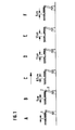
- Square or rectangular tiles of various dimensions are fired in a roller furnace, as is shown schematically in FIG. 1.
- the kiln is divided into different sections A - F.
- section A the tiles are placed and introduced into the kiln.
- Section B can be referred to as a drying or preheating zone.
- a normal distance of 5 cm between the individual tiles in the transport direction is set here.
- Section B is followed by sections C and D, which form the actual firing zone.
- Section E represents a transition into the cooling zone, section F.
- section C the rollers are driven faster, so that the distance between them increases, for example, to 8.5 cm.
- the rollers in section D run a little faster, so that the distance increases further, for example to 12 cm.
- the drive speed in section E corresponds to that in section D, so that the distance is maintained.
- section F the rollers are then driven more slowly again, so that essentially the distance from section B is restored.
- the distance is chosen so large by increasing the speed of the rollers that this goal is achieved. If a touch is no longer critical, the distance can be reduced again. This is the case when the glaze in the cooling zone has hardened to such an extent that contact no longer leads to sticking.
- Fig. 2 is a graph showing the temperature curve over the length of the furnace.
- the individual sections A - F correspond to those in FIG. 1.
- the times given in minutes are the respective throughput speeds in the furnace, which results in a total residence time of 45.8 'in the example shown.
- the method according to the invention can advantageously be carried out as described, i.e. by accelerating the rollers in the area of the burning zone, i.e. at the latest when contact in the area of the glazed edges must be prevented with certainty. If only in this area is accelerated and thus the distance is increased, the desired goal is achieved without the stove having to be extended unnecessarily, since the distance is kept correspondingly small in the other areas in which contact is not critical.
- the method according to the invention can also be carried out by accepting a somewhat longer furnace length or a correspondingly slower mode of operation in such a way that a large distance in the transport direction is maintained from the outset. Interim solutions are also conceivable.
Landscapes
- Chemical & Material Sciences (AREA)
- Engineering & Computer Science (AREA)
- Ceramic Engineering (AREA)
- Organic Chemistry (AREA)
- Materials Engineering (AREA)
- Structural Engineering (AREA)
- Inorganic Chemistry (AREA)
- Mechanical Engineering (AREA)
- Dispersion Chemistry (AREA)
- General Engineering & Computer Science (AREA)
- Tunnel Furnaces (AREA)
- Finishing Walls (AREA)
- Devices For Post-Treatments, Processing, Supply, Discharge, And Other Processes (AREA)
- Aftertreatments Of Artificial And Natural Stones (AREA)
Abstract
Description
- Die Erfindung betrifft ein Verfahren und eine Vorrichtung nach dem Oberbegriff des Anspruchs 1.
- Zum Brennen von Fliesen haben sich Rollenöfen sehr bewährt, da durch ihre Verwendung die Brennzeit stark herabgesetzt werden konnte. Dies gilt insbe- . sondere im Verhältnis zu Tunnelöfen mit Brennwagen. Die Herabsetzung der Brennzeit, d.h. derVerweilzeit in dem Ofen, hat unmittelbar Einfluß auf den Energieverbrauch.
- In der Praxis werden zunehmend Fliesen verlangt, die an mindestens einer Kante; häufig an zwei aneinander angrenzenden Kanten, glasiert sind. Diese sind dann die Kanten, die bei Abschlüssen und Ecken nach dem Verlegen der Fliesen sichtbar bleiben. Um eine komplizierte Lagerhaltung zu vermeiden, kann es daher sinnvoll sein, von vornherein sämtliche Fliesen an mindestens einer Kante zu glasieren. Wenn derartige Fliesen zum Brennen durch einen Brennofen bewegt werden, muß sichergestellt werden, daß sich diese mit den glasierten Kantenricht berühren. Eine derartige Berührung führt in der Brennzone zu einer Verbindung, die nach dem Austritt der Fliese aus dem Ofen nur durch Zerstörung wieder gelöst werden kann. Um eine solche Berührung zu verhindern, aber dennoch das Brennen in einem Rollenofen durchführen zu können, werden Zwischenträger verwendet, auf die die zu brennenden Fliesen aufgelegt werden und die dann von den Rollen durch den Rollenofen bewegt werden. Diese Zwischenträger verhindern, daß sich die FLiesen während des Transportes nennenswert gegeneinander verschieben, so daß sich die Fliesen an ihren glasierten Kanten auch nicht berühren können. Wenn die Fliesen ohne einen derartigen Zwischenträger, d.h. durch unmittelbares Auflegen auf die Rollen durch einen Rollenofen transportiert werden, verschieben sie sich relativ stark gegeneinander. Insbesondere die außen liegenden Fliesen werden im Verhältnis zu den im Bereich der Mittellinie liegenden Fliesen stärker bewegt, so daß es zu Berührungen im Bereich der glasierten Kanten kommt.
- Zum Brennen von Steinzeug, das während des Brennens stark schrumpft (im Bereich von 7 ö) ist es bereits vorgeschlagen worden, die Rollen unter Berücksichtigung des Schrumpfens in Transportrichtung fortschreitend entsprechend langsamer anzutreiben, um den Abstand zwischen dem Steinzeug möglichst konstant zu halten und so keinen wertvollen Raum zu verschenken.
- Der Erfindung liegt die Aufgabe zugrunde, ein Verfahren und eine Vorrichtung der eingangs genannten Art zu schaffen, die ein möglichst wirtschaftliches Brennen von an mindestens einer Kante glasierten Fliesen in einem Rollenofen ermöglichen, ohne dabei das Risiko einzugehen, daß sich die Fliesen an ihren glasierten Kanten" berühren und damit zusammenkleben.
- Diese Aufgabe wird durch das Kennzeichen des Anspruches 1 gelöst.
- Erfindungsgemäß werden die an einer Kante glasierten Fliesen unmittelbar auf die Rollen aufgelegt. Auf die Verwendung eines Zwischenträgers wird verzichtet. Hierdurch wird Energie eingespart, da der Zwischenträger nicht mit erwärmt und anschließend wieder abgekühlt werden muß. Weiterhin wird der Abstand zwischen den Kanten der Fliesen so groß gehalten, daß ein Berühren in der Brennzone verhindert wird.
- In der Brennzone wird die Glasur so weich oder flüssig, daß eine Berührung zu einem Verkleben führt. Wenn die Glasur dann erkaltet, sitzen die Fliesen entsprechend fest aneinander, so daß sie Ausschuß darstellen. Dieses wird durch die Erfindung verhindert.
- In vorteilhafter Weise wird der gewünschte Abstand durch die Maßnahme des Anspruches 2 bewerkstelligt. In dem Bereich, nämlich in der Brennzone, in dem eine Berührung verhindert werden muß, werden die Rollen schneller angetrieben, so daß sich der Abstand hier so weit vergrößert, daß die Berührung sicher verhindert wird.
- Im Anschluß an die Brennzone, d.h. in der Kühlzone, kann dann wieder etwas langsamer gefahren werden, so daß sich der Abstand wieder verringert. Auf der einen Seite wird ein möglichst geringer Abstand angestrebt, damit der Ofen zur Sicherstellung einer bestimmten Verweilzeit nicht unnötig lang ausgeführt werden muß, zum anderen wird der Abstand in dem Bereich, in dem mit Sicherheit eine Berührung verhindert werden soll, so groß gemacht, daß dieses Ziel erreicht wird.
- Eine Vorrichtung, d.h. ein Rollenofen zur Durchführung des erfindungsgemäßen Verfahrens ist Gegenstand der Ansprüche 4 und 5.
- Im folgenden wird die Erfindung unter Hinweis auf die Zeichnung anhand eines Ausführungsbeispiels näher erläutert.
- Es zeigen:
- Fig. 1 eine schematische Seitenansicht eines Rollenofens zur Durchführung des erfindungsgemäßen Verfahrens; und
- Fig. 2 eine grafische Darstellung zur Veranschaulichung des Abstandes zwischen den Fliesen im Verhältnis zu der Behandlungstemperatur in einem Rollenofen nach Fig. 1.
- In einem Rollenofen, wie er schematisch in Fig. 1 dargestellt ist, werden quadratische oder rechteckige Fliesen unterschiedlichster Abmessungen gebrannt. Es liegen hierbei mehrere Fliesen nebeneinander. Wenn diese Fliesen lediglich an einer Kante glasiert sind, so liegt diese Kante senkrecht zur Transportrichtung, vorzugsweise vorne. Wenn zwei aneinander angrenzende Kanten einer Fiiese glasiert sind, so muß der seitliche Abstand, d.h. der Abstand senkrecht zur Transportrichtung, von vornherein so groß sein, daß hier eine Berührung sicher verhindert wird. Seitlich verrutschen die Fliesen wärend des Transportes aber nicht so stark, so daß der Abstand in Transportrichtung als der kritischere bezeichnet werden kann. Im übrigen werden die meisten Fliesen auch nur an einer Kante glasiert.
- Der Brennofen gliedert sich in verschiedene Abschnitte A - F. In dem Abschnitt A werden die Fliesen aufgelegt und in den Brennofen eingeführt. Der Abschnitt B kann als Trocken- oder Vorwärmzone bezeichnet werden. Hier wird ein normaler Abstand von beispielsweise 5 cm zwischen den einzelnen Fliesen in Transportrichtung eingestellt.
- An den Abschnitt B schließen sich die Abschnitte C und D an, die die eigentliche Brennzone bilden. Der Abschnitt E stellt einen Übergang in die Kühlzone, den Abschnitt F, dar.
- Im Abschnitt C werden die Rollen schneller angetrieben, so daß sich der Abstand zwischen ihnen beispielsweise auf 8,5 cm vergrößert. Die Rollen im Abschnitt D laufen noch etwas schneller, so daß der Abstand sich weiter erhöht, beispielsweise auf 12 cm. Die Antriebsgeschwindigkeit im Abschnitt E entspricht derjenigen im Abschnitt D, so daß der Abstand erhalten bleibt. Im Abschnitt F werden die Rollen dann wieder langsamer angetrieben, so daß sich im wesentlichen der Abstand aus dem Abschnitt B wieder einstellt.
- Es ist ersichtlich, daß in den Abschnitten, d.h. in der Brennzone, in der mit Sicherheit ein Berühren verhindert werden muß, der Abstand durch Erhöhung der Geschwindigkeit der Rollen so groß gewählt wird, daß dieses Ziel erreicht wird. Wenn dann eine Berührung nicht mehr kritisch ist, kann der Abstand wieder verringert werden. Dies ist dann der Fall, wenn die Glasur in der Kühlzone schon so weit erhärtet ist, daß eine Berührung nicht mehr zum Verkleben führt.
- In der Fig. 1 sind die FLiesen mit 1, die Rollen mit 2 und die Antriebe mit 3 bezeichnet.
- Fig. 2 ist ein Schaubild, in dem der Temperaturverlauf über die Ofenlänge dargestellt ist. Die einzelnen Abschnitte A - F entsprechen denjenigen der Fig. 1. Die angegebenen Zeiten in Minuten sind die jeweiligen Durchlaufgeschwindigkeiten im Ofen, woraus sich bei dem dargestellten Beispiel eine Gesamtverweilzeit von 45,8' ergibt.
- Das erfindungsgemäße Verfahren läßt sich in vorteilhafter Weise so durchführen wie beschrieben, d.h. durch Beschleunigung der Rollen im Bereich der Brennzone, d.h. spätestens dann, wenn eine Berührung im Bereich der glasierten Kanten mit Sicherheit verhindert werden muß. Wenn lediglich in diesem Bereich beschleunigt und damit der Abstand vergrößert wird, wird das gewünschte Ziel erreicht, ohne daß der Ofen unnötig verlängert werden muß, da in den übrigen Bereichen, in denen eine Berührung nicht kritisch ist, der Abstand entsprechend gering gehalten wird. Es ist aber verständlich, daß das erfindungsgemäße Verfahren unter Inkaufnahme einer noch etwas größeren Ofenlänge oder einer entsprechend langsameren Fahrweise auch so durchgeführt werden kann, daß von vornherein ein großer Abstand in Transportrichtung eingehalten wird. Zwischenlösungen sind ebenfalls denkbar.
Claims (5)
dadurch gekennzeichnet,
daß die Fliesen unmittelbar auf die Rollen aufgelegt und von diesen transportiert werden, und daß der Abstand zwischen den Kanten der Fliesen so bemessen wird, daß eine Berührung während des Durchlaufs durch die Brennzone verhindert wird.
dadurch gekennzeichnet,
daß die Fliesen mit der glasierten Kante nach vorn oder hinten angeordnet werden und die Rollen in der Brennzone schneller als die Rollen vor der Brennzone angetrieben werden, so daß sich der Abstand zwischen den Kanten der Fliesen in Transportrichtung vergrößert.
dadurch gekennzeichnet,
daß die Rollen hinter der Brennzone wieder langsamer angetrieben werden, um den Abstand zwischen den Kanten der FLiesen wieder zu verringern.
daß die Rollen (2) in der Brennzone (C,D) mit höherer Geschwindigkeit antreibbar sind als in den anderen Zonen.
dadurch gekennzeichnet,
daß die Rollen (2) in der Brennzone in zwei Abschnitte (C,D) zusammengefaßt sind, von denen die Rollen des in Transportrichtung ersten Abschnitts (C) etwas langsamer als die Rollen des anschließenden Abschnitts (D) antreibbar sind.
Applications Claiming Priority (2)
| Application Number | Priority Date | Filing Date | Title |
|---|---|---|---|
| DE3345850 | 1983-12-19 | ||
| DE19833345850 DE3345850A1 (de) | 1983-12-19 | 1983-12-19 | Verfahren und vorrichtung zum brennen von an mindestens einer kante glasierten fliesen |
Publications (3)
| Publication Number | Publication Date |
|---|---|
| EP0145944A2 true EP0145944A2 (de) | 1985-06-26 |
| EP0145944A3 EP0145944A3 (en) | 1985-07-31 |
| EP0145944B1 EP0145944B1 (de) | 1988-01-20 |
Family
ID=6217351
Family Applications (1)
| Application Number | Title | Priority Date | Filing Date |
|---|---|---|---|
| EP84113546A Expired EP0145944B1 (de) | 1983-12-19 | 1984-11-09 | Verfahren und Vorrichtung zum Brennen von glasierten Fliesen |
Country Status (4)
| Country | Link |
|---|---|
| EP (1) | EP0145944B1 (de) |
| JP (1) | JPS60131883A (de) |
| DE (2) | DE3345850A1 (de) |
| ES (1) | ES538006A0 (de) |
Cited By (1)
| Publication number | Priority date | Publication date | Assignee | Title |
|---|---|---|---|---|
| EP0270043A3 (de) * | 1986-11-28 | 1990-04-04 | A.P.T. Anlagen für Pyrotechnik GmbH | Verfahren zur Wärmebehandlung von insbesondere im wesentlichen flachen Körpern aus keramischem Material und Durchlaufofen für die Durchführung des Verfahrens |
Families Citing this family (1)
| Publication number | Priority date | Publication date | Assignee | Title |
|---|---|---|---|---|
| DE4240252A1 (en) * | 1991-12-02 | 1993-08-05 | Iduso Gmbh | Sandwich channelled ceramic plate - has glazing between plates with same thermal expansion as the plate clay for bonding during firing |
Family Cites Families (5)
| Publication number | Priority date | Publication date | Assignee | Title |
|---|---|---|---|---|
| CH425594A (de) * | 1964-07-27 | 1966-11-30 | Armrock Products Inc | Verfahren und Brennofen zur Herstellung von unglasierten und glasierten Formkörpern |
| US3606281A (en) * | 1970-05-22 | 1971-09-20 | Gen Electric | Roller hearth furnace with roll oscillation controller |
| US3985495A (en) * | 1974-04-26 | 1976-10-12 | United States Ceramic Tile Company | Method and apparatus for fast firing glazed ceramic tile trim pieces |
| US4183885A (en) * | 1974-04-29 | 1980-01-15 | Pietro Marazzi | Quick baking process for ceramic products |
| FR2447526A1 (fr) * | 1979-01-29 | 1980-08-22 | Holcroft & Co | Four a sole, a rouleaux |
-
1983
- 1983-12-19 DE DE19833345850 patent/DE3345850A1/de not_active Withdrawn
-
1984
- 1984-11-09 EP EP84113546A patent/EP0145944B1/de not_active Expired
- 1984-11-09 DE DE8484113546T patent/DE3468936D1/de not_active Expired
- 1984-11-12 JP JP59236892A patent/JPS60131883A/ja active Pending
- 1984-11-27 ES ES538006A patent/ES538006A0/es active Granted
Cited By (1)
| Publication number | Priority date | Publication date | Assignee | Title |
|---|---|---|---|---|
| EP0270043A3 (de) * | 1986-11-28 | 1990-04-04 | A.P.T. Anlagen für Pyrotechnik GmbH | Verfahren zur Wärmebehandlung von insbesondere im wesentlichen flachen Körpern aus keramischem Material und Durchlaufofen für die Durchführung des Verfahrens |
Also Published As
| Publication number | Publication date |
|---|---|
| DE3345850A1 (de) | 1985-06-27 |
| EP0145944B1 (de) | 1988-01-20 |
| EP0145944A3 (en) | 1985-07-31 |
| JPS60131883A (ja) | 1985-07-13 |
| ES8600728A1 (es) | 1985-11-01 |
| ES538006A0 (es) | 1985-11-01 |
| DE3468936D1 (en) | 1988-02-25 |
Similar Documents
| Publication | Publication Date | Title |
|---|---|---|
| DE69116026T2 (de) | Ofen und transportverfahren zum heizen von glasscheiben | |
| DE102006020781B3 (de) | Ofen | |
| EP0767891B1 (de) | Vorrichtung zur temperaturbehandlung von produkten durch mikrowellenbestrahlung | |
| DE3640727C2 (de) | ||
| DE69833871T2 (de) | Vorrichtung zur härtung gebogenen glasscheiben | |
| EP0236666B1 (de) | Arbeitsverfahren zum Aufheizen von in Stranggusseinrichtungen gegossenen oder in Umformeinrichtungen umgeformten Halbzeugen für deren Einbringen in Umform- und/oder Weiterverarbeitungseinrichtungen | |
| DE2434614A1 (de) | Verfahren und vorrichtung zur waermebehandlung von glastafeln | |
| DE69209001T2 (de) | Verfahren zur Dampfbehandlung eines Druckplattenträgers und Gerät dafür | |
| DE69617356T2 (de) | Verfahren und Vorrichtung zum Egalisieren des Temperaturprofils eines Ofens mit kontrollierter Umgebungsoxidation | |
| DE69018919T2 (de) | Brennofen für Pulverlacke. | |
| DE2907960A1 (de) | Verfahren und vorrichtung zum kontinuierlichen waermebehandeln von vereinzeltem, langgestrecktem metallischen gut | |
| DE3783383T2 (de) | Verfahren zur kuehlung von gebrannten produkten in einem ofen. | |
| EP0145944B1 (de) | Verfahren und Vorrichtung zum Brennen von glasierten Fliesen | |
| EP0093877B1 (de) | Vorrichtung zur Wärmebehandlung von stückigem Gut bei hoher Temperatur | |
| DE68922710T2 (de) | Ofen für Trocknung oder Behandlung von lichtempfindlichem Material, welches als Schicht auf ein Trägermaterial aufgebracht ist. | |
| EP0062796B1 (de) | Anlage für die Behandlung von warmen und/oder zu erwärmenden Glasscheiben | |
| EP0059849B1 (de) | Verfahren zum Herstellen eines Farbspiels beim Brennen von flächigem keramischen Brenngut | |
| DE68906359T2 (de) | Ofen zum Wärmen, Halten und Speichern metallurgischer Produkte. | |
| DE2741098A1 (de) | Vorrichtung zum thermischen vorspannen von glasscheiben, insbesondere durchlaufofen | |
| DE3535668A1 (de) | Verfahren und vorrichtung zur waermebehandlung von glasscheiben | |
| DE102020106139A1 (de) | Thermisches Behandeln eines Bauteils | |
| DE2627135A1 (de) | Haertungsvorrichtung fuer glastafeln | |
| WO1994026940A1 (de) | Vorrichtung zur wärmebehandlung metallischer werkstücke | |
| EP4015657B1 (de) | Thermisches behandeln von bauteilen | |
| DE3437237C2 (de) |
Legal Events
| Date | Code | Title | Description |
|---|---|---|---|
| PUAI | Public reference made under article 153(3) epc to a published international application that has entered the european phase |
Free format text: ORIGINAL CODE: 0009012 |
|
| PUAL | Search report despatched |
Free format text: ORIGINAL CODE: 0009013 |
|
| AK | Designated contracting states |
Designated state(s): DE FR GB IT NL |
|
| AK | Designated contracting states |
Designated state(s): DE FR GB IT NL |
|
| 17P | Request for examination filed |
Effective date: 19850719 |
|
| 17Q | First examination report despatched |
Effective date: 19861201 |
|
| GRAA | (expected) grant |
Free format text: ORIGINAL CODE: 0009210 |
|
| AK | Designated contracting states |
Kind code of ref document: B1 Designated state(s): DE FR GB IT NL |
|
| REF | Corresponds to: |
Ref document number: 3468936 Country of ref document: DE Date of ref document: 19880225 |
|
| RAP2 | Party data changed (patent owner data changed or rights of a patent transferred) |
Owner name: VILLEROY & BOCH AKTIENGESELLSCHAFT |
|
| ITF | It: translation for a ep patent filed | ||
| GBT | Gb: translation of ep patent filed (gb section 77(6)(a)/1977) | ||
| ET | Fr: translation filed | ||
| PLBI | Opposition filed |
Free format text: ORIGINAL CODE: 0009260 |
|
| 26 | Opposition filed |
Opponent name: BUCHTAL GMBH Effective date: 19881019 |
|
| NLR1 | Nl: opposition has been filed with the epo |
Opponent name: BUCHTAL GMBH |
|
| PG25 | Lapsed in a contracting state [announced via postgrant information from national office to epo] |
Ref country code: GB Effective date: 19891109 |
|
| PGFP | Annual fee paid to national office [announced via postgrant information from national office to epo] |
Ref country code: NL Payment date: 19891130 Year of fee payment: 6 |
|
| PGFP | Annual fee paid to national office [announced via postgrant information from national office to epo] |
Ref country code: FR Payment date: 19900529 Year of fee payment: 6 |
|
| GBPC | Gb: european patent ceased through non-payment of renewal fee | ||
| ITPR | It: changes in ownership of a european patent |
Owner name: CESSIONE;RIEDHAMMER GMBH UND CO. KG |
|
| RAP2 | Party data changed (patent owner data changed or rights of a patent transferred) |
Owner name: RIEDHAMMER GMBH UND CO. KG |
|
| PG25 | Lapsed in a contracting state [announced via postgrant information from national office to epo] |
Ref country code: NL Effective date: 19910601 |
|
| PLBM | Termination of opposition procedure: date of legal effect published |
Free format text: ORIGINAL CODE: 0009276 |
|
| STAA | Information on the status of an ep patent application or granted ep patent |
Free format text: STATUS: OPPOSITION PROCEDURE CLOSED |
|
| NLT2 | Nl: modifications (of names), taken from the european patent patent bulletin |
Owner name: RIEDHAMMER GMBH & CO. KG TE NEURENBERG, BONDSREPUB |
|
| NLV4 | Nl: lapsed or anulled due to non-payment of the annual fee | ||
| PG25 | Lapsed in a contracting state [announced via postgrant information from national office to epo] |
Ref country code: FR Effective date: 19910731 |
|
| 27C | Opposition proceedings terminated |
Effective date: 19910331 |
|
| REG | Reference to a national code |
Ref country code: FR Ref legal event code: ST |
|
| ITTA | It: last paid annual fee | ||
| PGFP | Annual fee paid to national office [announced via postgrant information from national office to epo] |
Ref country code: DE Payment date: 19971115 Year of fee payment: 14 |
|
| PG25 | Lapsed in a contracting state [announced via postgrant information from national office to epo] |
Ref country code: DE Free format text: LAPSE BECAUSE OF NON-PAYMENT OF DUE FEES Effective date: 19990901 |