EP0142217B1 - Method and apparatus for flanging tubular polymer articles - Google Patents
Method and apparatus for flanging tubular polymer articles Download PDFInfo
- Publication number
- EP0142217B1 EP0142217B1 EP84304975A EP84304975A EP0142217B1 EP 0142217 B1 EP0142217 B1 EP 0142217B1 EP 84304975 A EP84304975 A EP 84304975A EP 84304975 A EP84304975 A EP 84304975A EP 0142217 B1 EP0142217 B1 EP 0142217B1
- Authority
- EP
- European Patent Office
- Prior art keywords
- die
- tubular article
- flanging
- flange
- tubular
- Prior art date
- Legal status (The legal status is an assumption and is not a legal conclusion. Google has not performed a legal analysis and makes no representation as to the accuracy of the status listed.)
- Expired
Links
Images

Classifications
-
- B—PERFORMING OPERATIONS; TRANSPORTING
- B29—WORKING OF PLASTICS; WORKING OF SUBSTANCES IN A PLASTIC STATE IN GENERAL
- B29C—SHAPING OR JOINING OF PLASTICS; SHAPING OF MATERIAL IN A PLASTIC STATE, NOT OTHERWISE PROVIDED FOR; AFTER-TREATMENT OF THE SHAPED PRODUCTS, e.g. REPAIRING
- B29C57/00—Shaping of tube ends, e.g. flanging, belling or closing; Apparatus therefor, e.g. collapsible mandrels
- B29C57/12—Rim rolling
-
- B—PERFORMING OPERATIONS; TRANSPORTING
- B29—WORKING OF PLASTICS; WORKING OF SUBSTANCES IN A PLASTIC STATE IN GENERAL
- B29B—PREPARATION OR PRETREATMENT OF THE MATERIAL TO BE SHAPED; MAKING GRANULES OR PREFORMS; RECOVERY OF PLASTICS OR OTHER CONSTITUENTS OF WASTE MATERIAL CONTAINING PLASTICS
- B29B13/00—Conditioning or physical treatment of the material to be shaped
- B29B13/02—Conditioning or physical treatment of the material to be shaped by heating
- B29B13/023—Half-products, e.g. films, plates
- B29B13/024—Hollow bodies, e.g. tubes or profiles
- B29B13/025—Tube ends
-
- B—PERFORMING OPERATIONS; TRANSPORTING
- B29—WORKING OF PLASTICS; WORKING OF SUBSTANCES IN A PLASTIC STATE IN GENERAL
- B29C—SHAPING OR JOINING OF PLASTICS; SHAPING OF MATERIAL IN A PLASTIC STATE, NOT OTHERWISE PROVIDED FOR; AFTER-TREATMENT OF THE SHAPED PRODUCTS, e.g. REPAIRING
- B29C57/00—Shaping of tube ends, e.g. flanging, belling or closing; Apparatus therefor, e.g. collapsible mandrels
-
- B—PERFORMING OPERATIONS; TRANSPORTING
- B29—WORKING OF PLASTICS; WORKING OF SUBSTANCES IN A PLASTIC STATE IN GENERAL
- B29C—SHAPING OR JOINING OF PLASTICS; SHAPING OF MATERIAL IN A PLASTIC STATE, NOT OTHERWISE PROVIDED FOR; AFTER-TREATMENT OF THE SHAPED PRODUCTS, e.g. REPAIRING
- B29C35/00—Heating, cooling or curing, e.g. crosslinking or vulcanising; Apparatus therefor
- B29C35/02—Heating or curing, e.g. crosslinking or vulcanizing during moulding, e.g. in a mould
- B29C35/04—Heating or curing, e.g. crosslinking or vulcanizing during moulding, e.g. in a mould using liquids, gas or steam
- B29C35/041—Heating or curing, e.g. crosslinking or vulcanizing during moulding, e.g. in a mould using liquids, gas or steam using liquids
- B29C2035/042—Heating or curing, e.g. crosslinking or vulcanizing during moulding, e.g. in a mould using liquids, gas or steam using liquids other than water
- B29C2035/043—Heating or curing, e.g. crosslinking or vulcanizing during moulding, e.g. in a mould using liquids, gas or steam using liquids other than water oil
-
- B—PERFORMING OPERATIONS; TRANSPORTING
- B29—WORKING OF PLASTICS; WORKING OF SUBSTANCES IN A PLASTIC STATE IN GENERAL
- B29C—SHAPING OR JOINING OF PLASTICS; SHAPING OF MATERIAL IN A PLASTIC STATE, NOT OTHERWISE PROVIDED FOR; AFTER-TREATMENT OF THE SHAPED PRODUCTS, e.g. REPAIRING
- B29C35/00—Heating, cooling or curing, e.g. crosslinking or vulcanising; Apparatus therefor
- B29C35/02—Heating or curing, e.g. crosslinking or vulcanizing during moulding, e.g. in a mould
- B29C35/08—Heating or curing, e.g. crosslinking or vulcanizing during moulding, e.g. in a mould by wave energy or particle radiation
- B29C35/0805—Heating or curing, e.g. crosslinking or vulcanizing during moulding, e.g. in a mould by wave energy or particle radiation using electromagnetic radiation
- B29C2035/0822—Heating or curing, e.g. crosslinking or vulcanizing during moulding, e.g. in a mould by wave energy or particle radiation using electromagnetic radiation using IR radiation
-
- B—PERFORMING OPERATIONS; TRANSPORTING
- B29—WORKING OF PLASTICS; WORKING OF SUBSTANCES IN A PLASTIC STATE IN GENERAL
- B29C—SHAPING OR JOINING OF PLASTICS; SHAPING OF MATERIAL IN A PLASTIC STATE, NOT OTHERWISE PROVIDED FOR; AFTER-TREATMENT OF THE SHAPED PRODUCTS, e.g. REPAIRING
- B29C35/00—Heating, cooling or curing, e.g. crosslinking or vulcanising; Apparatus therefor
- B29C35/02—Heating or curing, e.g. crosslinking or vulcanizing during moulding, e.g. in a mould
- B29C35/04—Heating or curing, e.g. crosslinking or vulcanizing during moulding, e.g. in a mould using liquids, gas or steam
- B29C35/045—Heating or curing, e.g. crosslinking or vulcanizing during moulding, e.g. in a mould using liquids, gas or steam using gas or flames
-
- B—PERFORMING OPERATIONS; TRANSPORTING
- B29—WORKING OF PLASTICS; WORKING OF SUBSTANCES IN A PLASTIC STATE IN GENERAL
- B29C—SHAPING OR JOINING OF PLASTICS; SHAPING OF MATERIAL IN A PLASTIC STATE, NOT OTHERWISE PROVIDED FOR; AFTER-TREATMENT OF THE SHAPED PRODUCTS, e.g. REPAIRING
- B29C35/00—Heating, cooling or curing, e.g. crosslinking or vulcanising; Apparatus therefor
- B29C35/02—Heating or curing, e.g. crosslinking or vulcanizing during moulding, e.g. in a mould
- B29C35/04—Heating or curing, e.g. crosslinking or vulcanizing during moulding, e.g. in a mould using liquids, gas or steam
- B29C35/049—Heating or curing, e.g. crosslinking or vulcanizing during moulding, e.g. in a mould using liquids, gas or steam using steam or damp
-
- B—PERFORMING OPERATIONS; TRANSPORTING
- B29—WORKING OF PLASTICS; WORKING OF SUBSTANCES IN A PLASTIC STATE IN GENERAL
- B29C—SHAPING OR JOINING OF PLASTICS; SHAPING OF MATERIAL IN A PLASTIC STATE, NOT OTHERWISE PROVIDED FOR; AFTER-TREATMENT OF THE SHAPED PRODUCTS, e.g. REPAIRING
- B29C35/00—Heating, cooling or curing, e.g. crosslinking or vulcanising; Apparatus therefor
- B29C35/16—Cooling
-
- B—PERFORMING OPERATIONS; TRANSPORTING
- B29—WORKING OF PLASTICS; WORKING OF SUBSTANCES IN A PLASTIC STATE IN GENERAL
- B29K—INDEXING SCHEME ASSOCIATED WITH SUBCLASSES B29B, B29C OR B29D, RELATING TO MOULDING MATERIALS OR TO MATERIALS FOR MOULDS, REINFORCEMENTS, FILLERS OR PREFORMED PARTS, e.g. INSERTS
- B29K2995/00—Properties of moulding materials, reinforcements, fillers, preformed parts or moulds
- B29K2995/0037—Other properties
- B29K2995/005—Oriented
- B29K2995/0053—Oriented bi-axially
-
- B—PERFORMING OPERATIONS; TRANSPORTING
- B29—WORKING OF PLASTICS; WORKING OF SUBSTANCES IN A PLASTIC STATE IN GENERAL
- B29L—INDEXING SCHEME ASSOCIATED WITH SUBCLASS B29C, RELATING TO PARTICULAR ARTICLES
- B29L2023/00—Tubular articles
- B29L2023/22—Tubes or pipes, i.e. rigid
-
- Y—GENERAL TAGGING OF NEW TECHNOLOGICAL DEVELOPMENTS; GENERAL TAGGING OF CROSS-SECTIONAL TECHNOLOGIES SPANNING OVER SEVERAL SECTIONS OF THE IPC; TECHNICAL SUBJECTS COVERED BY FORMER USPC CROSS-REFERENCE ART COLLECTIONS [XRACs] AND DIGESTS
- Y10—TECHNICAL SUBJECTS COVERED BY FORMER USPC
- Y10S—TECHNICAL SUBJECTS COVERED BY FORMER USPC CROSS-REFERENCE ART COLLECTIONS [XRACs] AND DIGESTS
- Y10S264/00—Plastic and nonmetallic article shaping or treating: processes
- Y10S264/71—Processes of shaping by shrinking
Definitions
- This invention relates to methods and apparatus for flanging tubular polymer articles, and more specifically to the flanging of the open ends of tubular articles or crystallisable thermoplastic polymers, particularly of saturated linear polyester materials such as polyethylene terephthalate.
- the tubular articles may be open at both ends or may have one open end and one closed end (integral or otherwise), and they may, for example, be used as bodies for processable food and beverage containers, in which case the or each flange will usually (but not necessarily) be provided for the purpose of being seamed to an end component, e.g. of metal.
- the tubular bodies may be of circular, rectangular or other cross-section.
- flanging metal can bodies preparatory to attaching metal end components by seaming.
- the flange is essentially cold swaged, using a number of rollers on a rotating head. If this method is applied to a body of a crystallisable thermoplastic polymer, the body is simply cut without any flange being formed. It is known to flange bodies made of fibre composite board for forming containers by pressing the end of the tubular body axially into a die, which is usually cold although it is known for it to be heated. So long as the moisture content of the fibre composite board is correct, a well defined flange can be rapidly produced. If this method is used with a tubular body of crystallisable thermoplastic, however, the flange substantially wholly recovers the original shape of the tubular body once the axial force has been released.
- biaxially drawn crystallisable thermoplastic polymers normally tend to shrink if heated above the temperature at which they were drawn, but that this tendency can be much reduced by annealing the material under restraint, e.g. at temperatures in the range of 150°Cto 230°C.
- This process is known as heat setting. It usually leaves the material with a residual linear shrinkage of up to about 3% which will appear on re-heating without restraint to the drawing temperature, but the heat-set articles are otherwise dimensionally stable and strong.
- An object of the present invention is to provide a method and apparatus by which a well defined flange can be reliably formed upon the end of a tubular article of a heat-set crystallisable thermoplastic polymer, e.g. a saturated linear polyester such as polyethylene terephthalate.
- a particular object is to enable the formation of such flanges on the open ends of tubular articles which are to form the bodies of containers, which are subsequently to be seamed to metal end components.
- a method of flanging a tubular article of a thermoplastic polymer by the steps of applying an end of the tubular article to a flanging die which engages the inner surface of the end, heating the said end of the tubular article to a flanging temperature at which the said thermoplastic polymer is softened, forcing the tubular article and the die together so that the heat-softened end of the tubular article is forced by the die to move outwards to form a flange, and causing the flanged end of the tubular article to cool, is characterised in that the tubular article is of a crystallisable thermoplastic polymer which, prior to flanging, has been drawn and heat-set to an elevated temperature, leaving the material with a residual shrinkage capability, and in that the flanging temperature is above the glass transition temperature of the polymer but below the elevated temperature to which it has been heat-set, so that when the flange is being formed by the forcing together of the tubular article and the die the material of the material of the tubular article
- This method makes use of the residual shrinkage in the polymer to ensure close contact of the flange with the die and consequent accurate formation of the flange, while the subsequent cooling of the flanged end under restraint minimizes further shrinkage and sets the flange to the required dimensions.
- forced cooling will normally be used; however, natural cooling may be used for some applications.
- the heating or artificial cooling of the end of the tubular article may be effected indirectly, by thermal conduction from or to the die.
- Such heating via the die may be effected by means of a heat source fixedly mounted in or adjacent to the die, or by means of a heat source separate from the die and removable therefrom.
- the heat source may be a conductive hot body of large thermal mass heated by an internal electrical cartridge heater, hot oil, hot air, or live steam, or a radiant heater such as an electrical heating coil which may operate in the infra-red region, or a direct flame heater.
- a heat source located in or adjacent to the die but separate therefrom can be continuously energised but removable from the die when a desired temperature has been achieved or when the die is to be cooled.
- the heating or artificial cooling of the end of the tubular article may be effected by heating or cooling the polymer directly by means located externally of the tubular article, e.g. by blown gas of the appropriate temperature or by an external radiant heater. Such direct heating of the end of the tubular article may be achieved before the end is brought into contact with the die.
- the die may be a metal end component of the container.
- the flanging operation can produce an assembly of container body and one or two metal end components ready for seaming.
- tubular article is open at both ends, it is possible to flange both ends simultaneously by application to similar flanging dies.
- the invention also resides in apparatus for flanging tubular articles of a crystallisable thermoplastic polymer by a method described above, comprising a first flanging die, arranged to engage one end of one of the tubular articles, means for holding the tubular article in position for application to said first flanging die, means for forcing the tubular article and said first flanging die together, and means for heating and means for cooling the said end of the tubular article, characterised in that the means for holding the tubular article comprises said first flanging die and a second flanging die arranged to engage the opposite end of the tubular article, said means for forcing the tubular article and said first flanging die together comprise means for forcing said first flanging die and said second flanging die together so that outward flanges are formed simultaneously at both ends of the tubular article.
- the apparatus may further comprise a stop ring disposed co-axially around the die to limit the outward movement of the end of the flange.
- Figure 1 illustrates a tubular body 10 of a crystallisable thermoplastic polymer, particularly a saturated linear polyester material such as polyethylene terephthalate, which has been formed with an out-turned flange 11 at its open end 12 in accordance with the method of the present invention.
- a crystallisable thermoplastic polymer particularly a saturated linear polyester material such as polyethylene terephthalate
- Figure 2 illustrates the form of the rim of an end component 14 which is to be seamed to the flange 11 so as to close the open end 12 of the container body 10.
- the end component 14 has an upwardly extending wall 15, a seaming panel 16 extending outwardly from the wall 15 and an inwardly curled portion 17 at its outer rim, terminating in an inwardly directed cut edge 18.
- a plastic lining compound 19 may, as shown, be provided on the underside of the seaming panel 16, if required to give a hermetic seal.
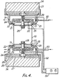
- the apparatus illustrated in Figure 4 is designed to produce such flanges on tubular bodies 10 of saturated linear polyester materials such as polyethylene terephthalate which are open at both ends.
- the apparatus is essentially symmetrical so that both ends of the body 10 can be flanged simultaneously.
- Both upper and lower portions of the apparatus include a metal die 20 having a vertical wall 21 and an out-turned horizontal flange 22 for forming the flanges 11.
- the die 20 is surrounded by a co-axial stop ring 23 whose inner periphery is spaced from the wall 21 by a distance equal to the desired width of the flange 11.
- the stop ring 23 is secured to a drum shaped housing 24 mounted through heat insulating pads 25, 26 on a base 27, while the die 20 is secured to the base 27 by a cap screw 28.
- the die 20 and stop ring 23 can thus be readily removed and exchanged for similar components of different size, in order to deal with container bodies 10 of corresponding different size.
- the housing 24 accommodates an electrical heating coil 29 and is provided with an inlet 30 and outlet 31 for cooling air.
- the heating coils 29 are connected through leads 32 to a temperature control apparatus 33.
- the base plates 27 are each mounted on a block or platen 34 of a hydraulic press.
- a cylindrical container body of biaxially drawn polyester material such as polyethylene terephthalate, which has been produced for example as disclosed in our published British Patent Application No. 8037137 (publication no. 2089276A) and which has been heat-set, for example as described in our co-pending British Patent Application No. 8310966, is placed in the apparatus as illustrated at 10, with its open ends in contact with the lead-in taper 35 of the top and bottom dies 20.
- the dies 20 are rapidly heated to a flanging temperature above the glass transition temperature of the polymer but below the temperature to which it has been heat-set, typically to 120°C for polyethylene terephthalate.
- a compressive load of up to 200 Kg, typically 30 Kg, is then applied to the body 10 by forcing the flanging dies 20 of the press towards one another by means (not shown) acting on the platens 34.
- the ends of the body 10 are thereby softened and forced to move outwards to form the flanges 11 until the end of the flange abuts against the stop ring 23.
- the polymer material of each flange tends to undergo residual shrinkage as the heat from the respective die 20 penetrates into it; this helps the polymer to take up the precise contours of the die 20 and to form a well defined flange.
- the heaters 29 are then switched off and the die 20 is force-cooled by cooling air introduced through the inlet 30 and exhausted through the outlet 31 until the temperature of the flanged end has dropped substantially to at least 20°C (typically 40°C) below the flanging temperatures and possibly to or beneath the glass transition temperature of the polymer. This stops or at least minimizes further thermal shrinkage and sets the flange to the required well defined dimensions.
- 20°C typically 40°C
- the axial load is then released and the flanged body 10 removed from the apparatus.
- one of the dies 20 may be replaced by a flat or shaped abutment to bear against the closed end of the container to apply the flanging load.
- a heater in the form of a removable conductive body of large thermal mass, i.e. a hot block, which is brought into direct contact with the die 20 for heating it but is removable therefrom for cooling.
- the hot block may be continuously energised, and may have an internal cartridge heater or be heated by circulation of hot oil, hot air or live steam, for example. Electrical resistance heating may be used, e.g. by passing a heating current through the operative part of the die. Inductive heating may also be used. Hot air circulation may also be used to heat the die.
- Cooling of the dies may be effected by means of a liquid coolant, rather than by cooling air as described above.
- the heating and/or the cooling means provided for each flange may be located externally of the tubular article so as to act directly on the flange material, and the die 20 may be used as a heat sink for cooling.
- One or both of the dies 20 may be a metal end component of the container, so that the flanging operation results in an assembly of container and end component which can then be passed immediately to a seaming machine.
- the container can be formed with an inwardly projecting neck below the or each flange, by providing the respective die with a corresponding annular reduction in the wall 21 into which the polymer material may shrink.
- the apparatus may be arranged to form flanges on container bodies 10 which are other than circular in section, e.g. rectangular or oval.
Landscapes
- Engineering & Computer Science (AREA)
- Mechanical Engineering (AREA)
- Physics & Mathematics (AREA)
- Thermal Sciences (AREA)
- Shaping Of Tube Ends By Bending Or Straightening (AREA)
- Processing And Handling Of Plastics And Other Materials For Molding In General (AREA)
- Addition Polymer Or Copolymer, Post-Treatments, Or Chemical Modifications (AREA)
- Treatments Of Macromolecular Shaped Articles (AREA)
- Rigid Pipes And Flexible Pipes (AREA)
- Blow-Moulding Or Thermoforming Of Plastics Or The Like (AREA)
- Extrusion Moulding Of Plastics Or The Like (AREA)
- Injection Moulding Of Plastics Or The Like (AREA)
- Multicomponent Fibers (AREA)
Priority Applications (1)
| Application Number | Priority Date | Filing Date | Title |
|---|---|---|---|
| AT84304975T ATE33585T1 (de) | 1983-07-22 | 1984-07-20 | Verfahren und vorrichtung zum umboerdeln rohrfoermiger polymerer gegenstaende. |
Applications Claiming Priority (2)
| Application Number | Priority Date | Filing Date | Title |
|---|---|---|---|
| GB8319768 | 1983-07-22 | ||
| GB08319768A GB2143461B (en) | 1983-07-22 | 1983-07-22 | Method and apparatus for flanging tubular polymer articles |
Publications (2)
| Publication Number | Publication Date |
|---|---|
| EP0142217A1 EP0142217A1 (en) | 1985-05-22 |
| EP0142217B1 true EP0142217B1 (en) | 1988-04-20 |
Family
ID=10546110
Family Applications (1)
| Application Number | Title | Priority Date | Filing Date |
|---|---|---|---|
| EP84304975A Expired EP0142217B1 (en) | 1983-07-22 | 1984-07-20 | Method and apparatus for flanging tubular polymer articles |
Country Status (13)
| Country | Link |
|---|---|
| US (1) | US4559197A (es) |
| EP (1) | EP0142217B1 (es) |
| JP (1) | JPS6038125A (es) |
| AT (1) | ATE33585T1 (es) |
| AU (1) | AU569096B2 (es) |
| CA (1) | CA1240468A (es) |
| DE (1) | DE3470481D1 (es) |
| DK (1) | DK336084A (es) |
| ES (1) | ES8606092A1 (es) |
| GB (1) | GB2143461B (es) |
| GR (1) | GR82233B (es) |
| IN (1) | IN161683B (es) |
| SG (1) | SG11589G (es) |
Cited By (2)
| Publication number | Priority date | Publication date | Assignee | Title |
|---|---|---|---|---|
| DE4442268C1 (de) * | 1994-11-28 | 1996-01-04 | Deutsche Forsch Luft Raumfahrt | Welle mit integrierten Winkelausgleichselementen aus faserverstärkten Kunstharzen |
| US5725434A (en) * | 1994-11-28 | 1998-03-10 | Deutsche Forschungsanstalt Fur Luft-Un Raumfahrt E. V. | Shaft of fibre-reinforced material |
Families Citing this family (12)
| Publication number | Priority date | Publication date | Assignee | Title |
|---|---|---|---|---|
| JPS6267531U (es) * | 1985-10-17 | 1987-04-27 | ||
| US4948006A (en) * | 1986-12-02 | 1990-08-14 | Dai Nippon Insatsu Kabushiki Kaisha | Container with metallic cover and method of manufacturing the same |
| GB2205065A (en) * | 1987-05-27 | 1988-11-30 | Metal Box Plc | Methods and apparatus for flanging tubular polymer articles |
| AU621575B2 (en) * | 1987-11-02 | 1992-03-19 | Scripps Clinic And Research Foundation | Diagnostic methods and systems for quantifying apo ai |
| JPH0639126B2 (ja) * | 1990-07-19 | 1994-05-25 | 東洋製罐株式会社 | 熱可塑性樹脂罐胴のフランジ成形装置 |
| NL9400894A (nl) * | 1994-06-01 | 1996-01-02 | Wavin Bv | Werkwijze en inrichting voor het vormen van een mof aan een buis van biaxiaal georiënteerd thermoplastisch kunststofmateriaal. |
| WO1996001179A1 (en) * | 1994-07-06 | 1996-01-18 | Drypac Pty. Ltd. | Packaging |
| JP3936743B2 (ja) * | 1996-04-24 | 2007-06-27 | 株式会社 吉野工業所 | チューブ容器の加工方法と加工装置 |
| US6062408A (en) * | 1997-04-09 | 2000-05-16 | Dtl Technology Limited Partnership | Wide mouth hot fill container |
| US6109006A (en) * | 1998-07-14 | 2000-08-29 | Advanced Plastics Technologies, Ltd. | Process for making extruded pet containers |
| US20060255049A1 (en) * | 2002-08-09 | 2006-11-16 | Fort James Corporation | Stretch blow-molded stackable tumbler |
| CN114851533B (zh) * | 2022-04-21 | 2023-04-28 | 南通理工学院 | 一种钢衬四氟直管的自动翻边装置 |
Family Cites Families (18)
| Publication number | Priority date | Publication date | Assignee | Title |
|---|---|---|---|---|
| GB593982A (en) * | 1945-06-21 | 1947-10-30 | Lines Bros Ltd | Improvements relating to means for retaining wheels, pedals or the like on axles |
| GB639997A (en) * | 1947-02-12 | 1950-07-12 | Communications Patents Ltd | The production of flared or flanged tubes of thermoplastic material |
| FI24833A (fi) * | 1948-04-15 | 1951-01-10 | Menettelytapa putkimaisen kappaleen, esim. lukkopesän, liittämiseksi päittäin levyn, esim. lukon etulevyn, pintaan | |
| GB895444A (en) * | 1958-07-08 | 1962-05-02 | Foster Brothers Plastics Ltd | Method of forming flanges on the ends of thermoplastic pipe |
| US3142868A (en) * | 1962-07-02 | 1964-08-04 | Socony Mobil Oil Co Inc | Flanging tool |
| US3445552A (en) * | 1966-09-29 | 1969-05-20 | Pennsylvania Fluorocarbon Co I | Process for making corrugated plastic tubing |
| FR1552001A (es) * | 1967-10-20 | 1969-01-03 | ||
| DE1808110C3 (de) * | 1968-11-09 | 1973-12-20 | Dynamit Nobel Ag | Verfahren und Vorrichtung zum An formen einer Muffe am Ende eines Rohres aus thermoplastischem Kunststoff |
| US3889443A (en) * | 1969-09-30 | 1975-06-17 | Sprinter Pack Ab | Method of forming a container with lid for liquids, especially carbonized beverages |
| FR2128161B1 (es) * | 1971-03-09 | 1973-12-28 | Labarre M | |
| US3933298A (en) * | 1974-02-14 | 1976-01-20 | Boise Cascade Corporation | End seam construction for composite containers |
| US4156710A (en) * | 1974-12-04 | 1979-05-29 | Phillips Petroleum Company | Fabrication of a flange adapter for plastic pipe |
| NL183279C (nl) * | 1975-02-28 | 1988-09-16 | Polva Nederland Bv | Werkwijze voor het vormen van een mof aan het uiteinde van een buis van thermoplastische kunststof. |
| US4134949A (en) * | 1977-02-17 | 1979-01-16 | Harsco Corporation | Method to form a bell end in a plastic pipe |
| NL7702866A (nl) * | 1977-03-16 | 1978-09-19 | Klaas Hendrik Klasema | Werkwijze en inrichting voor het vormen van een flens aan een buisvormig element van kunst- stof. |
| JPS62274Y2 (es) * | 1979-09-07 | 1987-01-07 | ||
| US4383966A (en) * | 1981-06-29 | 1983-05-17 | Phillips Petroleum Company | Method and apparatus for forming a flange on thermoplastic tubing |
| JPS58153624A (ja) * | 1982-03-09 | 1983-09-12 | Toyobo Co Ltd | ポリエステル容器の筒体開口部の処理方法 |
-
1983
- 1983-07-22 GB GB08319768A patent/GB2143461B/en not_active Expired
-
1984
- 1984-07-06 DK DK336084A patent/DK336084A/da not_active Application Discontinuation
- 1984-07-09 US US06/628,848 patent/US4559197A/en not_active Expired - Fee Related
- 1984-07-11 CA CA000458684A patent/CA1240468A/en not_active Expired
- 1984-07-17 JP JP59148502A patent/JPS6038125A/ja active Granted
- 1984-07-18 ES ES534428A patent/ES8606092A1/es not_active Expired
- 1984-07-19 AU AU30836/84A patent/AU569096B2/en not_active Ceased
- 1984-07-20 DE DE8484304975T patent/DE3470481D1/de not_active Expired
- 1984-07-20 EP EP84304975A patent/EP0142217B1/en not_active Expired
- 1984-07-20 AT AT84304975T patent/ATE33585T1/de active
- 1984-07-20 GR GR75385A patent/GR82233B/el unknown
- 1984-07-21 IN IN532/MAS/84A patent/IN161683B/en unknown
-
1989
- 1989-02-18 SG SG115/89A patent/SG11589G/en unknown
Cited By (2)
| Publication number | Priority date | Publication date | Assignee | Title |
|---|---|---|---|---|
| DE4442268C1 (de) * | 1994-11-28 | 1996-01-04 | Deutsche Forsch Luft Raumfahrt | Welle mit integrierten Winkelausgleichselementen aus faserverstärkten Kunstharzen |
| US5725434A (en) * | 1994-11-28 | 1998-03-10 | Deutsche Forschungsanstalt Fur Luft-Un Raumfahrt E. V. | Shaft of fibre-reinforced material |
Also Published As
| Publication number | Publication date |
|---|---|
| AU569096B2 (en) | 1988-01-21 |
| JPH0214183B2 (es) | 1990-04-06 |
| IN161683B (es) | 1988-01-16 |
| JPS6038125A (ja) | 1985-02-27 |
| DE3470481D1 (en) | 1988-05-26 |
| GR82233B (es) | 1984-12-13 |
| DK336084A (da) | 1985-01-23 |
| ATE33585T1 (de) | 1988-05-15 |
| SG11589G (en) | 1989-09-29 |
| ES8606092A1 (es) | 1986-04-01 |
| EP0142217A1 (en) | 1985-05-22 |
| DK336084D0 (da) | 1984-07-06 |
| GB2143461A (en) | 1985-02-13 |
| AU3083684A (en) | 1985-01-24 |
| US4559197A (en) | 1985-12-17 |
| GB2143461B (en) | 1987-07-01 |
| GB8319768D0 (en) | 1983-08-24 |
| CA1240468A (en) | 1988-08-16 |
| ES534428A0 (es) | 1986-04-01 |
Similar Documents
| Publication | Publication Date | Title |
|---|---|---|
| EP0142217B1 (en) | Method and apparatus for flanging tubular polymer articles | |
| US4555373A (en) | Pressing of reinforced thermosetting polymer articles | |
| US5942259A (en) | Method and apparatus of controlling temperature of injection preform for stretch blow molding | |
| US3893882A (en) | Method for lining drums with plastic material | |
| US9527239B2 (en) | Method of converting a plastic container refurbishing machine to a plastic container reforming machine | |
| US4745245A (en) | Method and apparatus for the manufacture of a clad tube through use of induction heating | |
| US3504817A (en) | Closure and method of applying same | |
| US5753175A (en) | Method of molding a heat-resistant container and a set of molds for the method | |
| US3522124A (en) | Method for producing a sealing joint between thin sheets | |
| US4560430A (en) | Method of making a metallic container | |
| US20070126152A1 (en) | Methods and apparatuses for reforming an upper portion of a blow molded plastic container | |
| US3400111A (en) | Method for making integral containers having precisely parallel vertical walls | |
| US4431398A (en) | Apparatus for adjusting the temperature of a parison for stretch blow molding | |
| US3867086A (en) | Apparatus for molding a plastic container | |
| US3929952A (en) | Method for molding a plastic container | |
| JPH02196632A (ja) | 筒状容器の高周波溶着装置 | |
| JPH02160529A (ja) | 熱可塑性樹脂製品の成形方法および装置 | |
| JPH09235128A (ja) | プレス成形加熱装置及びプレス成形加熱方法 | |
| SU1706775A2 (ru) | Устройство дл электроконтактного нагрева металлических заготовок | |
| JPS6315899B2 (es) | ||
| GB2143761A (en) | Method of making a metallic container | |
| SU1706774A1 (ru) | Способ электроконтактного нагрева листовых металлических заготовок | |
| GB2136347A (en) | Forming tubular closed-ended articles of thermoformable polymer material | |
| CA1067260A (en) | Apparatus for forming closure liners | |
| JPH01165421A (ja) | 耐熱性合成樹脂容器の成形方法及び装置 |
Legal Events
| Date | Code | Title | Description |
|---|---|---|---|
| PUAI | Public reference made under article 153(3) epc to a published international application that has entered the european phase |
Free format text: ORIGINAL CODE: 0009012 |
|
| AK | Designated contracting states |
Designated state(s): AT BE CH DE FR GB IT LI LU NL SE |
|
| 17P | Request for examination filed |
Effective date: 19850826 |
|
| 17Q | First examination report despatched |
Effective date: 19860715 |
|
| GRAA | (expected) grant |
Free format text: ORIGINAL CODE: 0009210 |
|
| AK | Designated contracting states |
Kind code of ref document: B1 Designated state(s): AT BE CH DE FR IT LI LU NL SE |
|
| REF | Corresponds to: |
Ref document number: 33585 Country of ref document: AT Date of ref document: 19880515 Kind code of ref document: T |
|
| ITF | It: translation for a ep patent filed |
Owner name: JACOBACCI & PERANI S.P.A. |
|
| REF | Corresponds to: |
Ref document number: 3470481 Country of ref document: DE Date of ref document: 19880526 |
|
| ET | Fr: translation filed | ||
| PG25 | Lapsed in a contracting state [announced via postgrant information from national office to epo] |
Ref country code: LU Free format text: LAPSE BECAUSE OF NON-PAYMENT OF DUE FEES Effective date: 19880731 |
|
| BECN | Be: change of holder's name |
Effective date: 19880420 |
|
| RAP2 | Party data changed (patent owner data changed or rights of a patent transferred) |
Owner name: MB GROUP PLC |
|
| PLBE | No opposition filed within time limit |
Free format text: ORIGINAL CODE: 0009261 |
|
| STAA | Information on the status of an ep patent application or granted ep patent |
Free format text: STATUS: NO OPPOSITION FILED WITHIN TIME LIMIT |
|
| NLT2 | Nl: modifications (of names), taken from the european patent patent bulletin |
Owner name: MB GROUP PLC TE READING, GROOT-BRITTANNIE. |
|
| 26N | No opposition filed | ||
| PGFP | Annual fee paid to national office [announced via postgrant information from national office to epo] |
Ref country code: FR Payment date: 19890607 Year of fee payment: 6 Ref country code: AT Payment date: 19890607 Year of fee payment: 6 |
|
| PGFP | Annual fee paid to national office [announced via postgrant information from national office to epo] |
Ref country code: SE Payment date: 19890612 Year of fee payment: 6 |
|
| PGFP | Annual fee paid to national office [announced via postgrant information from national office to epo] |
Ref country code: CH Payment date: 19890613 Year of fee payment: 6 |
|
| PGFP | Annual fee paid to national office [announced via postgrant information from national office to epo] |
Ref country code: BE Payment date: 19890623 Year of fee payment: 6 |
|
| PGFP | Annual fee paid to national office [announced via postgrant information from national office to epo] |
Ref country code: DE Payment date: 19890630 Year of fee payment: 6 |
|
| PGFP | Annual fee paid to national office [announced via postgrant information from national office to epo] |
Ref country code: LU Payment date: 19890707 Year of fee payment: 6 |
|
| ITTA | It: last paid annual fee | ||
| PGFP | Annual fee paid to national office [announced via postgrant information from national office to epo] |
Ref country code: NL Payment date: 19890731 Year of fee payment: 6 |
|
| PG25 | Lapsed in a contracting state [announced via postgrant information from national office to epo] |
Ref country code: AT Effective date: 19900720 |
|
| PG25 | Lapsed in a contracting state [announced via postgrant information from national office to epo] |
Ref country code: SE Effective date: 19900721 |
|
| PG25 | Lapsed in a contracting state [announced via postgrant information from national office to epo] |
Ref country code: LI Effective date: 19900731 Ref country code: CH Effective date: 19900731 Ref country code: BE Effective date: 19900731 |
|
| BERE | Be: lapsed |
Owner name: MB GROUP P.L.C. Effective date: 19900731 |
|
| PG25 | Lapsed in a contracting state [announced via postgrant information from national office to epo] |
Ref country code: NL Effective date: 19910201 |
|
| NLV4 | Nl: lapsed or anulled due to non-payment of the annual fee | ||
| REG | Reference to a national code |
Ref country code: CH Ref legal event code: PL |
|
| PG25 | Lapsed in a contracting state [announced via postgrant information from national office to epo] |
Ref country code: FR Effective date: 19910329 |
|
| PG25 | Lapsed in a contracting state [announced via postgrant information from national office to epo] |
Ref country code: DE Effective date: 19910403 |
|
| REG | Reference to a national code |
Ref country code: FR Ref legal event code: ST |
|
| EUG | Se: european patent has lapsed |
Ref document number: 84304975.0 Effective date: 19910402 |