EP0141802A2 - Procédé d'élimination du soufre ou des composés sulfureux et/ou d'autres polluants de gaz chauds ainsi qu'un dispositif pour la réalisation de ce procédé - Google Patents
Procédé d'élimination du soufre ou des composés sulfureux et/ou d'autres polluants de gaz chauds ainsi qu'un dispositif pour la réalisation de ce procédé Download PDFInfo
- Publication number
- EP0141802A2 EP0141802A2 EP84890173A EP84890173A EP0141802A2 EP 0141802 A2 EP0141802 A2 EP 0141802A2 EP 84890173 A EP84890173 A EP 84890173A EP 84890173 A EP84890173 A EP 84890173A EP 0141802 A2 EP0141802 A2 EP 0141802A2
- Authority
- EP
- European Patent Office
- Prior art keywords
- coating
- pollutants
- coated
- reactor
- bodies
- Prior art date
- Legal status (The legal status is an assumption and is not a legal conclusion. Google has not performed a legal analysis and makes no representation as to the accuracy of the status listed.)
- Withdrawn
Links
- 239000003344 environmental pollutant Substances 0.000 title claims abstract description 77
- 231100000719 pollutant Toxicity 0.000 title claims abstract description 77
- 239000007789 gas Substances 0.000 title claims abstract description 76
- 238000000034 method Methods 0.000 title claims description 26
- NINIDFKCEFEMDL-UHFFFAOYSA-N Sulfur Chemical compound [S] NINIDFKCEFEMDL-UHFFFAOYSA-N 0.000 title claims description 8
- 239000011593 sulfur Substances 0.000 title claims description 8
- 229910052717 sulfur Inorganic materials 0.000 title claims description 8
- 150000003464 sulfur compounds Chemical class 0.000 title claims description 5
- 230000008569 process Effects 0.000 title description 7
- 238000000576 coating method Methods 0.000 claims abstract description 75
- 239000011248 coating agent Substances 0.000 claims abstract description 64
- 239000000203 mixture Substances 0.000 claims abstract description 13
- 239000002245 particle Substances 0.000 claims abstract description 12
- 239000000463 material Substances 0.000 claims abstract description 8
- 239000007787 solid Substances 0.000 claims abstract description 4
- 238000004140 cleaning Methods 0.000 claims description 11
- 239000000428 dust Substances 0.000 claims description 7
- 230000001105 regulatory effect Effects 0.000 claims description 7
- UQSXHKLRYXJYBZ-UHFFFAOYSA-N iron oxide Inorganic materials [Fe]=O UQSXHKLRYXJYBZ-UHFFFAOYSA-N 0.000 claims description 6
- 235000013980 iron oxide Nutrition 0.000 claims description 4
- 150000004649 carbonic acid derivatives Chemical class 0.000 claims description 3
- 239000000654 additive Substances 0.000 claims description 2
- 239000003513 alkali Substances 0.000 claims description 2
- 229910000287 alkaline earth metal oxide Inorganic materials 0.000 claims description 2
- 238000001514 detection method Methods 0.000 claims description 2
- 238000011156 evaluation Methods 0.000 claims description 2
- 150000004679 hydroxides Chemical class 0.000 claims description 2
- 235000014413 iron hydroxide Nutrition 0.000 claims description 2
- VBMVTYDPPZVILR-UHFFFAOYSA-N iron(2+);oxygen(2-) Chemical class [O-2].[Fe+2] VBMVTYDPPZVILR-UHFFFAOYSA-N 0.000 claims description 2
- 239000008188 pellet Substances 0.000 claims description 2
- 239000002912 waste gas Substances 0.000 abstract 1
- 238000006243 chemical reaction Methods 0.000 description 6
- 238000001816 cooling Methods 0.000 description 6
- 238000011068 loading method Methods 0.000 description 6
- MWUXSHHQAYIFBG-UHFFFAOYSA-N nitrogen oxide Inorganic materials O=[N] MWUXSHHQAYIFBG-UHFFFAOYSA-N 0.000 description 6
- 239000000126 substance Substances 0.000 description 6
- 230000008859 change Effects 0.000 description 5
- 238000013461 design Methods 0.000 description 5
- 239000007788 liquid Substances 0.000 description 5
- ZAMOUSCENKQFHK-UHFFFAOYSA-N Chlorine atom Chemical compound [Cl] ZAMOUSCENKQFHK-UHFFFAOYSA-N 0.000 description 4
- PXGOKWXKJXAPGV-UHFFFAOYSA-N Fluorine Chemical compound FF PXGOKWXKJXAPGV-UHFFFAOYSA-N 0.000 description 4
- ODINCKMPIJJUCX-UHFFFAOYSA-N calcium oxide Inorganic materials [Ca]=O ODINCKMPIJJUCX-UHFFFAOYSA-N 0.000 description 4
- 235000012255 calcium oxide Nutrition 0.000 description 4
- 239000000460 chlorine Substances 0.000 description 4
- 229910052801 chlorine Inorganic materials 0.000 description 4
- 229910052731 fluorine Inorganic materials 0.000 description 4
- 239000011737 fluorine Substances 0.000 description 4
- 241000273930 Brevoortia tyrannus Species 0.000 description 3
- 241001295925 Gegenes Species 0.000 description 3
- 230000006978 adaptation Effects 0.000 description 3
- BRPQOXSCLDDYGP-UHFFFAOYSA-N calcium oxide Chemical class [O-2].[Ca+2] BRPQOXSCLDDYGP-UHFFFAOYSA-N 0.000 description 3
- 239000000292 calcium oxide Substances 0.000 description 3
- 238000002485 combustion reaction Methods 0.000 description 3
- 238000006477 desulfuration reaction Methods 0.000 description 3
- 230000023556 desulfurization Effects 0.000 description 3
- 238000012545 processing Methods 0.000 description 3
- 238000000926 separation method Methods 0.000 description 3
- WKBOTKDWSSQWDR-UHFFFAOYSA-N Bromine atom Chemical compound [Br] WKBOTKDWSSQWDR-UHFFFAOYSA-N 0.000 description 2
- CDBYLPFSWZWCQE-UHFFFAOYSA-L Sodium Carbonate Chemical compound [Na+].[Na+].[O-]C([O-])=O CDBYLPFSWZWCQE-UHFFFAOYSA-L 0.000 description 2
- 238000004458 analytical method Methods 0.000 description 2
- RQNWIZPPADIBDY-UHFFFAOYSA-N arsenic atom Chemical compound [As] RQNWIZPPADIBDY-UHFFFAOYSA-N 0.000 description 2
- 229910000413 arsenic oxide Inorganic materials 0.000 description 2
- 239000002585 base Substances 0.000 description 2
- 230000015572 biosynthetic process Effects 0.000 description 2
- GDTBXPJZTBHREO-UHFFFAOYSA-N bromine Substances BrBr GDTBXPJZTBHREO-UHFFFAOYSA-N 0.000 description 2
- 229910000435 bromine oxide Inorganic materials 0.000 description 2
- AXCZMVOFGPJBDE-UHFFFAOYSA-L calcium dihydroxide Chemical compound [OH-].[OH-].[Ca+2] AXCZMVOFGPJBDE-UHFFFAOYSA-L 0.000 description 2
- 239000000920 calcium hydroxide Substances 0.000 description 2
- 229910001861 calcium hydroxide Inorganic materials 0.000 description 2
- 238000001704 evaporation Methods 0.000 description 2
- 230000008020 evaporation Effects 0.000 description 2
- 239000002737 fuel gas Substances 0.000 description 2
- 238000005259 measurement Methods 0.000 description 2
- 230000004048 modification Effects 0.000 description 2
- 238000012986 modification Methods 0.000 description 2
- 230000001590 oxidative effect Effects 0.000 description 2
- 238000000746 purification Methods 0.000 description 2
- 239000011734 sodium Substances 0.000 description 2
- UGFAIRIUMAVXCW-UHFFFAOYSA-N Carbon monoxide Chemical compound [O+]#[C-] UGFAIRIUMAVXCW-UHFFFAOYSA-N 0.000 description 1
- 238000005299 abrasion Methods 0.000 description 1
- 239000002250 absorbent Substances 0.000 description 1
- 230000002745 absorbent Effects 0.000 description 1
- 238000009825 accumulation Methods 0.000 description 1
- 239000013543 active substance Substances 0.000 description 1
- 235000010216 calcium carbonate Nutrition 0.000 description 1
- 235000011116 calcium hydroxide Nutrition 0.000 description 1
- 239000000969 carrier Substances 0.000 description 1
- 239000012876 carrier material Substances 0.000 description 1
- 239000003054 catalyst Substances 0.000 description 1
- 238000012993 chemical processing Methods 0.000 description 1
- 239000003153 chemical reaction reagent Substances 0.000 description 1
- 150000001875 compounds Chemical class 0.000 description 1
- 238000005108 dry cleaning Methods 0.000 description 1
- 230000000694 effects Effects 0.000 description 1
- 239000012717 electrostatic precipitator Substances 0.000 description 1
- 238000000605 extraction Methods 0.000 description 1
- 238000011049 filling Methods 0.000 description 1
- 239000003546 flue gas Substances 0.000 description 1
- 210000003918 fraction a Anatomy 0.000 description 1
- 238000002386 leaching Methods 0.000 description 1
- 239000008263 liquid aerosol Substances 0.000 description 1
- 229910044991 metal oxide Inorganic materials 0.000 description 1
- 150000004706 metal oxides Chemical class 0.000 description 1
- 230000003647 oxidation Effects 0.000 description 1
- 238000007254 oxidation reaction Methods 0.000 description 1
- 230000035699 permeability Effects 0.000 description 1
- JTJMJGYZQZDUJJ-UHFFFAOYSA-N phencyclidine Chemical class C1CCCCN1C1(C=2C=CC=CC=2)CCCCC1 JTJMJGYZQZDUJJ-UHFFFAOYSA-N 0.000 description 1
- 230000035484 reaction time Effects 0.000 description 1
- 230000009257 reactivity Effects 0.000 description 1
- 238000004064 recycling Methods 0.000 description 1
- 238000011946 reduction process Methods 0.000 description 1
- 239000011819 refractory material Substances 0.000 description 1
- 229910000029 sodium carbonate Inorganic materials 0.000 description 1
- 235000017550 sodium carbonate Nutrition 0.000 description 1
- 239000002904 solvent Substances 0.000 description 1
- 238000003786 synthesis reaction Methods 0.000 description 1
- 230000002123 temporal effect Effects 0.000 description 1
- 238000012549 training Methods 0.000 description 1
- 238000004056 waste incineration Methods 0.000 description 1
Images
Classifications
-
- B—PERFORMING OPERATIONS; TRANSPORTING
- B01—PHYSICAL OR CHEMICAL PROCESSES OR APPARATUS IN GENERAL
- B01D—SEPARATION
- B01D53/00—Separation of gases or vapours; Recovering vapours of volatile solvents from gases; Chemical or biological purification of waste gases, e.g. engine exhaust gases, smoke, fumes, flue gases, aerosols
- B01D53/34—Chemical or biological purification of waste gases
- B01D53/46—Removing components of defined structure
- B01D53/48—Sulfur compounds
- B01D53/50—Sulfur oxides
- B01D53/508—Sulfur oxides by treating the gases with solids
-
- B—PERFORMING OPERATIONS; TRANSPORTING
- B01—PHYSICAL OR CHEMICAL PROCESSES OR APPARATUS IN GENERAL
- B01D—SEPARATION
- B01D53/00—Separation of gases or vapours; Recovering vapours of volatile solvents from gases; Chemical or biological purification of waste gases, e.g. engine exhaust gases, smoke, fumes, flue gases, aerosols
- B01D53/02—Separation of gases or vapours; Recovering vapours of volatile solvents from gases; Chemical or biological purification of waste gases, e.g. engine exhaust gases, smoke, fumes, flue gases, aerosols by adsorption, e.g. preparative gas chromatography
- B01D53/06—Separation of gases or vapours; Recovering vapours of volatile solvents from gases; Chemical or biological purification of waste gases, e.g. engine exhaust gases, smoke, fumes, flue gases, aerosols by adsorption, e.g. preparative gas chromatography with moving adsorbents, e.g. rotating beds
- B01D53/08—Separation of gases or vapours; Recovering vapours of volatile solvents from gases; Chemical or biological purification of waste gases, e.g. engine exhaust gases, smoke, fumes, flue gases, aerosols by adsorption, e.g. preparative gas chromatography with moving adsorbents, e.g. rotating beds according to the "moving bed" method
-
- B—PERFORMING OPERATIONS; TRANSPORTING
- B01—PHYSICAL OR CHEMICAL PROCESSES OR APPARATUS IN GENERAL
- B01D—SEPARATION
- B01D2251/00—Reactants
- B01D2251/30—Alkali metal compounds
- B01D2251/304—Alkali metal compounds of sodium
-
- B—PERFORMING OPERATIONS; TRANSPORTING
- B01—PHYSICAL OR CHEMICAL PROCESSES OR APPARATUS IN GENERAL
- B01D—SEPARATION
- B01D2251/00—Reactants
- B01D2251/40—Alkaline earth metal or magnesium compounds
- B01D2251/404—Alkaline earth metal or magnesium compounds of calcium
-
- B—PERFORMING OPERATIONS; TRANSPORTING
- B01—PHYSICAL OR CHEMICAL PROCESSES OR APPARATUS IN GENERAL
- B01D—SEPARATION
- B01D2251/00—Reactants
- B01D2251/60—Inorganic bases or salts
- B01D2251/602—Oxides
-
- B—PERFORMING OPERATIONS; TRANSPORTING
- B01—PHYSICAL OR CHEMICAL PROCESSES OR APPARATUS IN GENERAL
- B01D—SEPARATION
- B01D2251/00—Reactants
- B01D2251/60—Inorganic bases or salts
- B01D2251/604—Hydroxides
-
- B—PERFORMING OPERATIONS; TRANSPORTING
- B01—PHYSICAL OR CHEMICAL PROCESSES OR APPARATUS IN GENERAL
- B01D—SEPARATION
- B01D2251/00—Reactants
- B01D2251/60—Inorganic bases or salts
- B01D2251/606—Carbonates
-
- B—PERFORMING OPERATIONS; TRANSPORTING
- B01—PHYSICAL OR CHEMICAL PROCESSES OR APPARATUS IN GENERAL
- B01D—SEPARATION
- B01D2253/00—Adsorbents used in seperation treatment of gases and vapours
- B01D2253/25—Coated, impregnated or composite adsorbents
-
- B—PERFORMING OPERATIONS; TRANSPORTING
- B01—PHYSICAL OR CHEMICAL PROCESSES OR APPARATUS IN GENERAL
- B01D—SEPARATION
- B01D2257/00—Components to be removed
- B01D2257/20—Halogens or halogen compounds
- B01D2257/202—Single element halogens
- B01D2257/2025—Chlorine
-
- B—PERFORMING OPERATIONS; TRANSPORTING
- B01—PHYSICAL OR CHEMICAL PROCESSES OR APPARATUS IN GENERAL
- B01D—SEPARATION
- B01D2257/00—Components to be removed
- B01D2257/20—Halogens or halogen compounds
- B01D2257/202—Single element halogens
- B01D2257/2027—Fluorine
-
- B—PERFORMING OPERATIONS; TRANSPORTING
- B01—PHYSICAL OR CHEMICAL PROCESSES OR APPARATUS IN GENERAL
- B01D—SEPARATION
- B01D2257/00—Components to be removed
- B01D2257/30—Sulfur compounds
- B01D2257/302—Sulfur oxides
-
- B—PERFORMING OPERATIONS; TRANSPORTING
- B01—PHYSICAL OR CHEMICAL PROCESSES OR APPARATUS IN GENERAL
- B01D—SEPARATION
- B01D2257/00—Components to be removed
- B01D2257/30—Sulfur compounds
- B01D2257/304—Hydrogen sulfide
-
- B—PERFORMING OPERATIONS; TRANSPORTING
- B01—PHYSICAL OR CHEMICAL PROCESSES OR APPARATUS IN GENERAL
- B01D—SEPARATION
- B01D2257/00—Components to be removed
- B01D2257/40—Nitrogen compounds
- B01D2257/404—Nitrogen oxides other than dinitrogen oxide
-
- B—PERFORMING OPERATIONS; TRANSPORTING
- B01—PHYSICAL OR CHEMICAL PROCESSES OR APPARATUS IN GENERAL
- B01D—SEPARATION
- B01D2259/00—Type of treatment
- B01D2259/40—Further details for adsorption processes and devices
- B01D2259/40007—Controlling pressure or temperature swing adsorption
- B01D2259/40009—Controlling pressure or temperature swing adsorption using sensors or gas analysers
-
- B—PERFORMING OPERATIONS; TRANSPORTING
- B01—PHYSICAL OR CHEMICAL PROCESSES OR APPARATUS IN GENERAL
- B01D—SEPARATION
- B01D2259/00—Type of treatment
- B01D2259/40—Further details for adsorption processes and devices
- B01D2259/40011—Methods relating to the process cycle in pressure or temperature swing adsorption
- B01D2259/40077—Direction of flow
- B01D2259/40081—Counter-current
Definitions
- the invention relates to a method for removing sulfur or sulfur compounds and / or other pollutants from hot gases, and to an apparatus for performing this method.
- GB-PS 157 845 has already disclosed a method of the type mentioned at the outset, in which particles are immersed in liquid and passed in free fall through gases to be cleaned. At higher temperatures, however, such a liquid evaporates and, in addition to the cooling of the exhaust gas that is required in this case, the freshly supplied, freely falling particles ensure further cooling of the gases. At higher temperatures, the decrease in viscosity of the liquid leads to dripping, to an enrichment of the liquid in the treatment room and finally to evaporation and renewed pollution of the exhaust gas.
- the invention now aims to provide an apparatus which is simple in terms of apparatus and with which a large number of exhaust gases which are different in their chemical analysis can be cleaned at a high temperature level without any noteworthy modifications, without significant modifications.
- the main aim of the method according to the invention is to achieve complete purification in the short term and without any technical changes in the system of the new composition of the exhaust gases when the exhaust gas composition changes.
- the invention consists essentially in that the hot gases after dedusting, by a bed of bodies of approximately uniform size made of heat-resistant and wear-resistant material, the surface of which is coated with a coating of solids, which has a great affinity for sulfur and / or has to the pollutants, that the coated bodies are guided in a circuit, the coating being at least partially mechanically removed from the bodies after they have been removed from the contact zone with the hot gases or is chemically removed and the bodies are returned to the bed after a new coating.
- the formation of the coating with solids allows, in contrast to liquid coatings, longer residence times and a higher temperature level in the almost standing column of the bed.
- the bed in contrast to particles carried in free fall, serves to maintain a temperature level which makes it possible to clean the gases without significantly cooling the gases to be cleaned.
- the dedusting can be done by cyclones, electrostatic precipitators or other dust separation devices before the hot gases are fed to a reaction shaft. Because a bed of bodies of approximately uniform size is used, a relatively low flow resistance can be ensured even at higher temperatures.
- the bodies of approximately uniform size, offer a relatively large surface for a corresponding coating, which is used to react with the pollutants.
- the reaction with the pollutants takes place on the surface of the coating, and by mechanically or chemically detaching this coating, appropriate processing of the compounds of the pollutants with the material of the coating can be carried out.
- the bodies which are largely freed of their coating, are subjected to a new coating, and changes in the analysis of the exhaust gases to be cleaned can be taken into account at short notice by choosing the appropriate reagents for the material of this coating.
- the extent of cleaning can be easily adjusted by changing the height of the feed.
- the material for the coating of the body can be adapted to the respective circumstances. In view of the stability of the bodies acting as supports, a correspondingly large one is always obtained even with mechanically less stable coatings Surface for the implementation with the pollutants in the exhaust gases ensured.
- the process can be carried out in the same way in the desulfurization or removal of pollutants from oxidizing and from reducing gases.
- the heat resistance of the carrier material of the bodies only has to be adapted to the temperatures to be expected and the mechanical strength or wear resistance must be sufficient to enable the coating to be removed repeatedly and the coating to be repeated several times.
- a number of refractory materials are suitable for this purpose and metallic base bodies can also be used without further notice.
- the sulfur compounds When working up the coating loaded with pollutants, the sulfur compounds can be burned, for example to SO 2 ' .
- a number of corresponding pyrochemical or wet chemical processing methods are available for other pollutants, the concentration of these pollutants in or on the coating ensuring an adequate accumulation of these pollutants, which enables economical processing.
- the coating of the bodies preferably consists of alkali and / or alkaline earth and / or iron oxides and / or hydroxides and / or carbonates.
- catalytically active additives can be used. With such coatings it is possible to bind a wide variety of sulfur compounds but also other volatile pollutants such as chlorine, fluorine, bromine, arsenic or nitrogen oxides.
- optionally catalytically active substances can be added. In a reducing atmosphere, such as occurs in converter exhaust gases at high temperatures, there is a coating of calcium oxide and Calcium hydroxide with a corresponding catalyst, such as iron oxide is particularly preferred.
- the bodies in the form of spheres or pellets are preferably used.
- the procedure is preferably that the composition and concentration of the pollutants in the feed line and the discharge line of the reactor are continuously monitored and the measured values are monitored with a Setpoint values are compared, and if the setpoint value is exceeded, the throughput speed of the coated bodies through the reactor is increased. Because the composition and concentration of the pollutants before and after the reactor is now used as a criterion for regulating the throughput speed of the feed to the reactor, a short-term adaptation to the requirements can be realized with maximum utilization of the reactivity of the coating.
- the extent of cleaning can be easily adjusted by changing the height of the feed.
- the material for the coating of the body can be adapted to the respective circumstances. In view of the stability of the bodies acting as carriers, a correspondingly large surface area for the reaction with the pollutants in the exhaust gases is always ensured even with mechanically less stable coatings.
- the adaptation to different pollutants can be improved in that the measured values for different pollutants each have a separate one for each pollutant or a group of pollutants Comparison with a corresponding setpoint specification and that the throughput speeds of the coated particles corresponding to the respective pollutants or groups of pollutants are regulated separately as a function of the measured values.
- the device according to the invention for carrying out this method is essentially characterized by a temperature-resistant reactor which can be filled with coated bodies, on one side of which a supply line for the hot gases is connected and a discharge opening for the coated bodies is arranged and on the side of which is turned away a discharge line for the hot gases are connected and a feed opening is provided for the coated bodies and a device for separating the coating of the bodies, the feed side of which is connected to the discharge opening of the temperature-resistant reactor and the discharge side of which is connected to a coating device for the new coating of the bodies, the outlet of the Coating device can be connected indirectly or directly to the feed opening of the reactor.
- the coating device of at least one, preferably several, parallel-connected coating drum (s) is advantageously used. educated.
- the measure of providing several coating drums allows the proportion of bodies which have a coating different from other bodies to be controlled to a large extent and specific coatings which are effective for individual pollutants contained in the exhaust gases can be controlled in the return the amount required for binding the respective proportion of these pollutants to the first reactor.
- the device for separating the coating is preferably designed as a rubbing drum or peeling drum. In such abrasion drums, the coated bodies are stripped of their coating in the presence of abrasive bodies or on sharp edges of peeling knives. The base bodies without this coating are then again fed to the coating system and provided with new coatings and returned to the reactor.
- the coating with the bound pollutants removed in the drum can be suctioned off in a particularly simple manner and can be separated out in a cyclone or dust filter.
- the design is such that the temperature-resistant reactor is elongated and is arranged essentially vertically, the feed opening for the coated bodies being arranged near the upper end and the feed line for the hot gases to be cleaned near the lower end.
- the small temperature difference between the inlet and outlet of the first reactor or reaction shaft is used for a directed flow, since the hot exhaust gases flow upwards.
- Such a design is particularly advantageous particularly at low pressure of the hot gases to be cleaned.
- the design is preferably such that the temperature-resistant reactor is designed to be pressure-resistant, it being possible in a particularly simple manner to switch on a controllable exhaust element in the discharge line of the temperature-resistant reactor.
- a sufficient dwell time of the exhaust gases to be cleaned can be ensured in the reaction shaft, which means that the structural Have the dimensions of the reaction shaft or the temperature-resistant reactor significantly reduced.
- this device is advantageously developed in such a way that at least one sensor for detecting the gas composition is connected to or in the supply line for the hot gases to a reactor and to or in the discharge line from the reactor that the Signals from the sensors are fed to an evaluation circuit and a comparator, that a discharge device and at least one feed device are provided for the coated bodies and that a control circuit connected to the comparator is connected to the drive of the discharge and / or feed devices.
- Such training creates the conditions for fully automated control of pollutant removal.
- the coating device is advantageously formed by at least one, preferably a plurality of coating drums connected in parallel.
- the measure of providing several coating drums allows the proportion of bodies which have a coating different from other bodies to be controlled to a large extent and specific coatings which are effective for individual pollutants contained in the exhaust gases can be controlled in the return the amount required to bind the respective proportion of these pollutants to the reactor.
- at least two feed devices are provided for bodies coated with different coatings, which are separately switchably connected to the control circuit, wherein the feed and / or discharge devices are preferably designed with adjustable delivery rates.
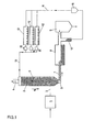
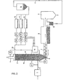
- FIG. 1 shows a first schematic illustration of the device according to the invention and FIG. 2 shows a modified embodiment with additional devices for a continuous detection of the gas composition and a corresponding regulation of the coating to be used.
- 1 denotes an electrostatic filter, with which the separation of dust from exhaust gases to be cleaned is possible by electrostatic means.
- 2 with a reactor is designated, to which the hot gases to be cleaned are supplied via a line 3.
- the cleaned hot gases exit via a shaft 4 and can be used for further use, for example combustion, in particular if the gases are reducing hot gases.
- a discharge opening 6 is provided, from which the coated particles are withdrawn via a screw conveyor 7.
- the coated particles migrate within the reactor 2 in the direction of arrow 14 against the flow of the gases to be cleaned.
- the coated bodies are fed to a rubbing drum 8, in which the used coating is ground off in the presence of friction bodies.
- the coating is applied by means of a dust extraction and dust separation device 9 and, after it has been separated off, can be sent for separate recycling or processing.
- the particles largely freed of their coating reach a return line 11 via a shaft 10. These are before return body now freed of its coating provided three coating drums 12 parallel to each other.
- metering devices which can be regulated in accordance with the gas composition can be installed in order to adjust the ratio of the bodies newly supplied to the individual coating drums 12 to be coated.
- coatings can be made in the coating drums and coatings can be achieved, for example, from calcium oxide, calcium hydroxide, iron oxide, sodium carbonate or other substances which can react with the pollutants.
- the newly coated bodies are in turn fed via a line 13 at the upper end of the reactor 2 and pass through this reactor 2 in the direction of the arrow 14 to re-bind SO 2 , H 2 S, chlorine, fluorine, NO x or similar pollutants.
- a collection bunker 16 is switched on in line 11. Intermediate bunkers 15 are provided for easier metering of the respectively coated particles.
- pollutant measuring devices 17 and 18 which work continuously are installed in the feed line 3 to the reactor and in the discharge line 4 from the reactor.
- the measured values determined here are registered and fed to a control unit 19, which continuously compares the pollutant fraction a 1 (%) remaining in the gas with the setpoint specification a (%) and controls the speed of the discharge screw, the motor of which is designated 21, and the metering.
- the feed devices are designated 20 here. If a pollutant with the content ao (%) is present, if the setpoint a s (%) is exceeded, the approx. 70 - 80% of the permissible emission value a 2 (%), the throughput speed v of the ball bed is increased via a discharge screw.
- the proportions of the coated bodies can be adapted to the ratio of the pollutant components.
- the concentration change in a pollutant component can be compensated for by changing the throughput speed v via the discharge screw, which must always be controlled by the worst pollutant component in comparison to the target specification.
- the disadvantage of this control method is that when there are major changes in concentration those bodies in which the pollutant concentration is below the target value are poorly used.
- the metering of the different types of coated bodies is controlled via the throughput speed v.
- a change in concentration (difference in the proportion of pollutants a 1 %, b 1 %, c l % in the cleaned exhaust gas to the target value a s %, b s %, c% in a particularly advantageous manner by changing the dosage of the individual types of coated bodies taken into account.
- This type of regulation presupposes that there is sufficient scope for increasing the ball bed height in the reactor in the case of increased metering in of individual types of coated bodies.
- the throughput speed can be increased.
- the change in the concentration of the pollutant in the exhaust gas is compensated for by changing the throughput speed v in the presence of a reactor filling volume, with which occurring pollutant peaks can also be controlled.
- the exhaust gas cleaned of dust is first subjected to a measurement of the pollutant content a 0 (%).
- the cleaning takes place at a speed v, the remaining pollutant fraction being measured again after the cleaning process has been completed and used as a 1 (%).
- This is followed by a comparison a 1 with the target specification a s (%), which corresponds to the prescribed emission value or a value below it.
- the throughput speed of the coated particles is increased. Conversely, if the nominal value is undershot, the throughput speed v of the coated particles is reduced. If the setpoint is adhered to exactly, there is no change in the throughput speed of the coated bodies. If the reaction time is short compared to the temporal fluctuations in the pollutant content, the system can be regulated very well.
- the target value generally corresponds to 70 - 80% of the permissible emission value.
- the ratio of the coated bodies is first determined and kept constant in accordance with an average content of pollutants.
- the changes in concentration are compensated for by changing the throughput speed.
- Example 2 The procedure is again as in Example 1 so that a dust-cleaned exhaust gas is first subjected to a measurement of the individual pollutant fractions, different fractions being determined for different pollutant components.
- a 0 (%) denotes the S0 2 content
- b 0 (%) the H 2 S content
- c 0 (%) the NO x content of the exhaust gases.
- the remaining pollutant fractions in the exiting exhaust gas are again measured.
- the measured values a 1 , b 1 and c 1 each result in percent.
- the throughput speed of the ball bed through the reactor depends on the loading time of the coated bodies, specifically on the loading of which takes the longest. If the ball bed height in the reactor is increased, the throughput time can therefore be shortened.
- B1 new + B2 new + B3 new e B new gives the total load B new and thus the throughput time t new .
- the designation t V / B newly the running speed v follows novel and can be regulated in this way.
- the method according to the invention can also be used for the purification of gases, solid-liquid aerosols, odorous substances and other substances.
- the coating of the body is then chosen according to the substances to be deposited.
- the removal of the adsorptively bound pollutants can be done by evaporation, oxidation or detachment using a solvent.
- suitable units such as. B. drum dryer, a combustion device or dry cleaning.
- CaO, Na 2 O, CaCO 3 , Na 2 CO 3 and MgO are primarily suitable as materials for further selective coatings, which means that S0 2 , HC1, HF and also N0 2 can be easily separated.
- MgO is not well suited as a coating for the removal of N0 2 .
Landscapes
- Chemical & Material Sciences (AREA)
- Engineering & Computer Science (AREA)
- Analytical Chemistry (AREA)
- General Chemical & Material Sciences (AREA)
- Oil, Petroleum & Natural Gas (AREA)
- Chemical Kinetics & Catalysis (AREA)
- Health & Medical Sciences (AREA)
- Biomedical Technology (AREA)
- Environmental & Geological Engineering (AREA)
- Treating Waste Gases (AREA)
- Physical Or Chemical Processes And Apparatus (AREA)
- Filtering Of Dispersed Particles In Gases (AREA)
Applications Claiming Priority (4)
| Application Number | Priority Date | Filing Date | Title |
|---|---|---|---|
| AT3589/83 | 1983-10-07 | ||
| AT0358983A AT379965B (de) | 1983-10-07 | 1983-10-07 | Verfahren zum entfernen von schwefel oder schwefelverbindungen und/oder anderen schadstoffenaus heissen gasen, sowie vorrichtung zur durchfuehrung dieses verfahrens |
| AT157984A AT382528B (de) | 1984-05-14 | 1984-05-14 | Verfahren zum entfernen von schwefel oder schwefelverbindungen und/oder anderen schadstoffenaus heissen gasen, sowie vorrichtung zur durchfuehrung dieses verfahrens |
| AT1579/84 | 1984-05-14 |
Publications (2)
| Publication Number | Publication Date |
|---|---|
| EP0141802A2 true EP0141802A2 (fr) | 1985-05-15 |
| EP0141802A3 EP0141802A3 (fr) | 1987-01-07 |
Family
ID=25596233
Family Applications (1)
| Application Number | Title | Priority Date | Filing Date |
|---|---|---|---|
| EP84890173A Withdrawn EP0141802A3 (fr) | 1983-10-07 | 1984-09-20 | Procédé d'élimination du soufre ou des composés sulfureux et/ou d'autres polluants de gaz chauds ainsi qu'un dispositif pour la réalisation de ce procédé |
Country Status (4)
| Country | Link |
|---|---|
| EP (1) | EP0141802A3 (fr) |
| KR (1) | KR850003331A (fr) |
| CS (1) | CS711784A2 (fr) |
| ES (1) | ES8604784A1 (fr) |
Cited By (5)
| Publication number | Priority date | Publication date | Assignee | Title |
|---|---|---|---|---|
| EP0203430A1 (fr) * | 1985-05-07 | 1986-12-03 | Phoenix Gesellschaft für Rauchgasreinigung und Umwelttechnik mbH | Procédé d'épuration des gaz de fumée et installation pour sa mise en oeuvre |
| EP0170355A3 (en) * | 1984-05-29 | 1987-08-26 | Ets, Inc. | Emission control process for combustion flue gases |
| DE3616618A1 (de) * | 1986-05-16 | 1987-11-19 | Horst Dr Grochowski | Verfahren zum behandeln von fluiden mittels adsorptionsmitteln |
| DE3641205A1 (de) * | 1986-12-03 | 1988-06-09 | Fhw Brenntechnik Gmbh | Vorrichtung zum filtern von umweltschaedlichen abgasen insbesondere von rauchgasen |
| WO2011039034A1 (fr) * | 2009-10-02 | 2011-04-07 | Torsten Schlicht | Agent de désulfuration minéral granuleux, à base d'hydoxyde de calcium, procédé de production et utilisation correspondants |
Family Cites Families (5)
| Publication number | Priority date | Publication date | Assignee | Title |
|---|---|---|---|---|
| SE409000B (sv) * | 1976-02-26 | 1979-07-23 | Lindstroem O | Saett och anordning foer att behandla ett gasfloede i en kontaktanordning |
| DE2755314A1 (de) * | 1977-12-12 | 1979-08-09 | Babcock Ag | Verfahren zur absorptiven entfernung von schwefeldioxid, chlor und fluor aus abgasen |
| US4322224A (en) * | 1980-10-29 | 1982-03-30 | General Electric Co. | Spray absorber control system and method |
| DE3122349C2 (de) * | 1981-06-05 | 1987-04-30 | Böhmeke, Albin, Prof. Dr., 5410 Höhr-Grenzhausen | Füllkörper für einen von Abgasen durchströmten Behälter, Verfahren zum Herstellen der Füllkörper und Verwendung zur Beseitigung von Schadstoffen, insbesondere von Flußsäure, Schwefeldioxid und Schwefeltrioxid aus diesen Abgasen |
| DE3234796C2 (de) * | 1982-09-20 | 1986-11-13 | Dr. Goldberg & Partner Umwelttechnik GmbH, 8000 München | Verfahren und Vorrichtung zum Abscheiden von gasförmigen Schadstoffen aus Rauchgasen mittels staubförmiger Additive |
-
1984
- 1984-09-20 EP EP84890173A patent/EP0141802A3/fr not_active Withdrawn
- 1984-09-21 CS CS847117A patent/CS711784A2/cs unknown
- 1984-10-04 KR KR1019840006138A patent/KR850003331A/ko not_active Withdrawn
- 1984-10-05 ES ES536551A patent/ES8604784A1/es not_active Expired
Cited By (5)
| Publication number | Priority date | Publication date | Assignee | Title |
|---|---|---|---|---|
| EP0170355A3 (en) * | 1984-05-29 | 1987-08-26 | Ets, Inc. | Emission control process for combustion flue gases |
| EP0203430A1 (fr) * | 1985-05-07 | 1986-12-03 | Phoenix Gesellschaft für Rauchgasreinigung und Umwelttechnik mbH | Procédé d'épuration des gaz de fumée et installation pour sa mise en oeuvre |
| DE3616618A1 (de) * | 1986-05-16 | 1987-11-19 | Horst Dr Grochowski | Verfahren zum behandeln von fluiden mittels adsorptionsmitteln |
| DE3641205A1 (de) * | 1986-12-03 | 1988-06-09 | Fhw Brenntechnik Gmbh | Vorrichtung zum filtern von umweltschaedlichen abgasen insbesondere von rauchgasen |
| WO2011039034A1 (fr) * | 2009-10-02 | 2011-04-07 | Torsten Schlicht | Agent de désulfuration minéral granuleux, à base d'hydoxyde de calcium, procédé de production et utilisation correspondants |
Also Published As
| Publication number | Publication date |
|---|---|
| ES536551A0 (es) | 1986-02-16 |
| EP0141802A3 (fr) | 1987-01-07 |
| KR850003331A (ko) | 1985-06-17 |
| ES8604784A1 (es) | 1986-02-16 |
| CS711784A2 (en) | 1985-07-16 |
Similar Documents
| Publication | Publication Date | Title |
|---|---|---|
| EP1964602B1 (fr) | Procédé de nettoyage de gaz d'échappement dans une installation d'incinération de déchets | |
| EP0415486B1 (fr) | Procédé et appareil pour la purification électrostatique d'effluents de gaz nocifs et poussiéreux dans des séparateurs à plusieurs champs | |
| DE3230472C2 (fr) | ||
| DE2712666A1 (de) | Sortierverfahren und -vorrichtung | |
| CH638107A5 (de) | Vorrichtung und verfahren zum absorbieren von verunreinigungen in abgasen. | |
| EP0228111B2 (fr) | Procédé pour l'élimination des substances nocives dans des gaz d'échappement | |
| DE69831862T2 (de) | Spritzgusssystem mit pellezufuhreinheit | |
| DE69501426T2 (de) | Verfahren zur Vorbereitung einer Mischung aus Bodenasche und Flugasche | |
| EP0740110B1 (fr) | Procédé et appareil pour le traitement de résidus solides de combustion d'un incinérateur | |
| EP3389828B1 (fr) | Procédé de séparation de substances gazeuses et particulaires présentes dans un flux de gaz au moyen d'un réacteur d'écoulement à lit fluidisé | |
| EP0141802A2 (fr) | Procédé d'élimination du soufre ou des composés sulfureux et/ou d'autres polluants de gaz chauds ainsi qu'un dispositif pour la réalisation de ce procédé | |
| DE2734619B2 (de) | Verfahren zum katalytischen Abbau von PolySchwefelwasserstoffen in flüssigem Schwefel | |
| DE3301872A1 (de) | Zerstaeubungstrockner und verfahren zum betrieb des trockners | |
| DE2834718A1 (de) | Verfahren zur kombinierten muellverwertung/abwasseraufbereitung und mehrstufen-filtrationsvorrichtung zur durchfuehrung des verfahrens | |
| AT382528B (de) | Verfahren zum entfernen von schwefel oder schwefelverbindungen und/oder anderen schadstoffenaus heissen gasen, sowie vorrichtung zur durchfuehrung dieses verfahrens | |
| DE3235020C2 (fr) | ||
| EP0196481B1 (fr) | Procédé et dispositif pour séparer des composés polluants d'un courant de gaz | |
| DE561899C (de) | Verfahren und Vorrichtung zur Ausfuehrung von Reaktionen zwischen verschiedenartigenGasen oder Daempfen und einem fein verteilten festen Stoff | |
| DE69722634T2 (de) | Verfahren zum Behandeln von Abgasen aus einer Verbrennung | |
| DE2702693C3 (de) | Vorrichtung zur Durchführung chemischer und/oder physikalischer Prozesse | |
| DE19961691C5 (de) | Verfahren zur Reinigung von Rauchgas | |
| DE3041997A1 (de) | Verfahren zur abtrennung von umweltschaedigenden gasen aus rauchgasen, insbesondere von tunneloefen, und vorrichtung zur durchfuehrung des verfahrens | |
| DD239127A5 (de) | Verfahren zum entschwefeln von rauchgasen | |
| DE2246806C2 (de) | Verfahren zur Reinigung von Abgasen | |
| DE4018488C1 (en) | Removing dust and hazardous materials from waste gases - by sepg. dust in dry multi-cyclone stage, and wet electrostatic precipitator stage |
Legal Events
| Date | Code | Title | Description |
|---|---|---|---|
| PUAI | Public reference made under article 153(3) epc to a published international application that has entered the european phase |
Free format text: ORIGINAL CODE: 0009012 |
|
| AK | Designated contracting states |
Designated state(s): BE DE FR GB IT LU NL SE |
|
| PUAL | Search report despatched |
Free format text: ORIGINAL CODE: 0009013 |
|
| AK | Designated contracting states |
Kind code of ref document: A3 Designated state(s): BE DE FR GB IT LU NL SE |
|
| STAA | Information on the status of an ep patent application or granted ep patent |
Free format text: STATUS: THE APPLICATION IS DEEMED TO BE WITHDRAWN |
|
| 18D | Application deemed to be withdrawn |
Effective date: 19870708 |
|
| RIN1 | Information on inventor provided before grant (corrected) |
Inventor name: JANUSCH, ALOIS, DIPL.-ING. Inventor name: FALTEJSEK, KARL, DIPL.-ING. Inventor name: HANS, WALTER |