EP0141018A2 - Montage d'armes à feu automatiques dans tourelle - Google Patents
Montage d'armes à feu automatiques dans tourelle Download PDFInfo
- Publication number
- EP0141018A2 EP0141018A2 EP84106798A EP84106798A EP0141018A2 EP 0141018 A2 EP0141018 A2 EP 0141018A2 EP 84106798 A EP84106798 A EP 84106798A EP 84106798 A EP84106798 A EP 84106798A EP 0141018 A2 EP0141018 A2 EP 0141018A2
- Authority
- EP
- European Patent Office
- Prior art keywords
- weapon
- barrel weapon
- barrel
- mount
- tube
- Prior art date
- Legal status (The legal status is an assumption and is not a legal conclusion. Google has not performed a legal analysis and makes no representation as to the accuracy of the status listed.)
- Granted
Links
Images

Classifications
-
- F—MECHANICAL ENGINEERING; LIGHTING; HEATING; WEAPONS; BLASTING
- F41—WEAPONS
- F41A—FUNCTIONAL FEATURES OR DETAILS COMMON TO BOTH SMALLARMS AND ORDNANCE, e.g. CANNONS; MOUNTINGS FOR SMALLARMS OR ORDNANCE
- F41A9/00—Feeding or loading of ammunition; Magazines; Guiding means for the extracting of cartridges
- F41A9/54—Cartridge guides, stops or positioners, e.g. for cartridge extraction
-
- F—MECHANICAL ENGINEERING; LIGHTING; HEATING; WEAPONS; BLASTING
- F41—WEAPONS
- F41A—FUNCTIONAL FEATURES OR DETAILS COMMON TO BOTH SMALLARMS AND ORDNANCE, e.g. CANNONS; MOUNTINGS FOR SMALLARMS OR ORDNANCE
- F41A27/00—Gun mountings permitting traversing or elevating movement, e.g. gun carriages
- F41A27/06—Mechanical systems
- F41A27/08—Bearings, e.g. trunnions; Brakes or blocking arrangements
- F41A27/10—Bearings for supporting a pivoting gun in a wall, e.g. a turret wall
Definitions
- the invention relates to an aperture mount for at least one vertically pivotable automatic barrel weapon according to the preamble of patent claim 1.
- the installation position of the machine gun in the faceplate also does not allow the barrel to be changed without removing the machine gun from the holder or without disassembling it.
- the invention has for its object to improve the aperture mount of the type mentioned in the preamble of claim 1 in such a way that the space required for pivoting at least one automatic barrel weapon (s) fastened within one or more roller barrel (s) which can be pivoted about a common elevation axis, preferably a machine gun, is reduced inside the turret without the discharge channels for belts and ammunition or the belt feed lines of your own or another barrel weapon are obstructed and inserting the ammunition belts, changing the barrel and installing and removing the barrel weapon inside the turret is possible.
- this solution only requires a very small swivel radius within the turret, which means that the space surrounding the barrel weapon within the roller cover is also optimal for the feed of the belts or Discharge channels of the propellant charge sleeves and belt parts of one or more tubular weapons arranged on an elevation axis can be used. Due to the possibility of retracting the barrel weapon in an index position that is always the same for inserting the ammunition belts, for changing the barrel and for installing and removing the barrel weapon, there is also space in the tower for, for example, op tisene devices, vertical straightening gear, the rotating ring bearing of the tower etc. created.
- the guide elements are designed as rods which can be retracted with the barrel weapon and are guided in an anti-glare slide guide, so that a sleeve deflecting shaft can reach the outside directly in the shortest possible way and below the slide guide and a partially pivotable belt link ejection channel through a cover plate. Because the upper part of the belt ejection channel located on the barrel weapon can be pivoted away, in the retracted position of the barrel weapon a barrel change can be carried out by pivoting the barrel down from the weapon holder.
- the guide elements are designed as T-rails, which can be connected to the roller cover as a lower mount in a horizontal and vertical position.
- a top mount is attached to the gun and equipped with spring elements from a firing position into a drawer - or exchange position of the barrel weapon retractable.
- the empty propellant charge sleeves directly through the side cover plate of the roller cover to the right into the open air and the sleeve discharge shaft can be used in a space-saving manner at the same time in a cranked arrangement as a sleeve discharge shaft passing underneath the tube weapon and of a further tube weapon arranged on the left side parallel to the tube weapon on the same elevation axis.
- the arrangement of a vertically pivotable barrel weapon, each equipped with its own roller blind, on the elevation axis of another barrel weapon advantageously allows the possibility of direct articulation of the aperture of the first barrel weapon through the aperture of the second barrel weapon.
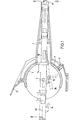
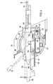
- an automatic barrel weapon 13 preferably a machine gun, seen on the left-hand side in the firing direction, is mounted within a roller shutter 3.
- the roller cover 3 is connected by the bearing 5 so as to be vertically pivotable to a horizontally rotatable tower 21 (not shown).
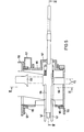
- a table 34 which is fixedly connected to it, is arranged inside the roller cover 3, on which a slide guide 20, which is displaceable in the lateral direction 35, is connected via known fastening means 37.
- two guide elements 17 designed as rods are slidably arranged in two guide bores 36 running in the axis-parallel direction of the barrel weapon 18, which are connected on one side at the rear end to a slide 16.
- the barrel weapon 18 is connected to the carriage 16 by a releasable bolt 14.
- the slide guide 20 receives two further rods 29 arranged axially parallel to the barrel weapon 18. These rods 29 are equipped with springs 32, 33, which are oppositely supported one behind the other on the slide guide 20, for receiving the recoil and forward forces of the barrel weapon 18, the Rods 29 in the front firing position 19 are connected to the slide 16 via two bayonet couplings 28.
- the flap 27 To load the barrel weapon 18, the flap 27 must be opened laterally. In the firing position 19, the flap 27 would abut the belt feed line 8 and the feed line, not shown, of a second barrel weapon 23, for example. To be able to nevertheless load properly the tube weapon 18, is retractable after loosening the form-locking connected to the carriage 16 bayonet coupling 28, by rotation of a mechanism not shown in detail at 90 0, the tube weapon 18, from an assumed index of 25, in a rear position 24 . In this position 24, the flap 27 for inserting the ammunition belts can be swung open in an opening area 40. In. In this position 24, the tube 31 can be changed by swiveling it down to the tube change position 26, and after the bolt 14 has been removed from the slide 16, the tube weapon 18 can be pulled completely out of the mount.
- the barrel weapon 18 is mounted in a gas-tight manner in a front attachment 7 in the front region by a ball ring 15 in the weft direction.
- the ball ring 15 is also in the rear position 24 out.
- the diaphragm attachment 7 is screwed onto the roller diaphragm 3 and protrudes from the opening of the diaphragm surface 1, which leaves the diaphragm seal 2 free.
- the roller screen 3 is supported on one side within the tower 21 on the left side in the tower wall 6 by the bearings 5 and the cover plate 12.
- the barrel weapon 18 is due to the displaceability of the slide guide 2 0 in both directions 35 of the Ele vationsachse 4 adjustable on the table 34.
- the barrel weapon 18 is rotated around the ball ring 15.
- a compensation of a possible oblique position of the barrel weapon 18 with respect to the elevation axis 4 of the roller screen 3 can be achieved by the bolt 14, for example by an adjustable thread.
- the empty cartridge casings can be derived in the shortest possible way directly horizontally from the barrel weapon 18 through the cover plate 12 mounted on the long side in the turret 21 in front of the carriage guide 20 in the direction 11.
- a section 38 of the belt ejection channel 13 which begins at the barrel weapon 18 is arranged to be pivotable away about an axis 39 lying parallel to the weapon.
- the ammunition belts are first guided in the direction 9 through the belt feed line 8 upwards and then from above into the barrel weapon 18.
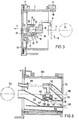
- FIGS. 4, 5 and -6 illustrates within a roller cover 103 a right-hand side arrangement in the firing direction of an automatic tube weapon 118, preferably a machine gun, the tube weapon 118 together with a spring-loaded top mount 144 on one with the roller panel 103 connected lower mount 145, from a front shooting position 119 to a rear position 124 for loading, for changing the barrel and the barrel weapon 118, is retractable.
- the upper mount 144 is connected to the barrel weapon 118 via the bolts 153, 154.
- the roller screen 103 can be swiveled vertically about the elevation axis 104 and is equipped with a screen seal 102 against rainwater and dust, a relatively short screen attachment 107 protruding from the screen surface 101 in the weft direction from the roller screen 103.
- the roller screen 103 is mounted on the right-hand outer tower wall 106 and on the left-hand side on the hood of the tower 121 about the elevation axis 104 in the bearing 105.
- the roller shutter 103 is articulated by a shutter 130 mounted in a common roller bearing 105, for example a machine gun.
- the lower mount 145 essentially consists of two T-rails 147, which are designed as guide elements 117 and are arranged axially parallel to the barrel weapon 118 and connected to one another via a base plate 150, on which the upper mount 144 is locked in the front firing position 119 by means of a fixation 146.
- the tubular weapon 118 fastened in this way like the tubular weapon 18 (FIG. 1), requires an extremely small pivoting space in the interior of the tower 121 due to the arrangement which is advanced far within the roller screen 103, 3 (FIG. 1). This arrangement allows the tube to be raised 31 (Fig. 1) and 131 from minus 15 ° to plus 55 °.
- the barrel weapon 118 with the upper mount 144 can be retracted after loosening the fixation 146 in the rear position 124, for inserting the ammunition belts, for changing the barrel 131 and the tubular gun 118 on the lower mount 145.
- the ammunition belts which can be removed from the belt feed line 108 are with the flap 127 open at the top, Seen on the left in the firing direction, can be inserted into the barrel weapon 118.
- the tube change of the tube 131 can also be carried out in the weft direction on the left side of the tube weapon 118 in a manner not shown.
- the barrel weapon 18 can be pulled completely out of the guide of the lower mount 145 with the upper mount 144 to the rear. After a loading process, tube change or weapon change, the tube weapon 118 is automatically locked in the front shooting position 119 by the fixation 146.
- the lower mount 145 is connected to the shortened diaphragm attachment 107 with respect to the elevation axis 104 via a horizontally and vertically adjustable bearing 151.
- the bearing 151 consists of a lower bearing half which is rotatably mounted about a vertical axis 142 in the diaphragm attachment 107 and of an upper bearing half which is fastened to the front end of the lower mount 145 and receives the lower bearing half in a horizontally lying axis 141.
- the advanced installation position of the tube weapon 118 allows the belt feed line 108 to be arranged on the upper inner edge of the roller cover 103 and a sleeve discharge shaft 110 of the tube weapon 118 downward into the sleeve discharge shaft 152 of a further tube weapon 123.
- the sleeve discharge shaft 152 passes under the tube weapon 118, a further shaft 143 of the second barrel weapon 123 also leads below the sleeve discharge shaft 152 through the cover plate 112 to the right into the open.
- the belt link ejection channel 113 of the barrel weapon 118 likewise opens out through the cover plate 112.
- the empty propellant charge casings of the barrel weapon 118 are ver from above into the multiple horizontal and obliquely inclined through the sleeve discharge shaft 110 passing between the T-rails 147
- Running sleeve discharge shaft 152 wherein the sleeve discharge shaft 110 is provided at the confluence with the sleeve discharge shaft 152 with a baffle plate 148 influencing the discharge direction of the empty propellant charge sleeves, by means of which the propellant charge sleeves can be deflected in such a way that they can be ejected directly in the direction 111 through the outlet opening 149 into the open are.
- This emission is not affected by an unfavorable position of the vehicle, for example an inclined position.
- the roller cover 103 is pushed into the roller bearing 105 from the right-hand side during assembly and the cover attachment 107 is then screwed on.
Landscapes
- Engineering & Computer Science (AREA)
- General Engineering & Computer Science (AREA)
- Toys (AREA)
- Filling Or Emptying Of Bunkers, Hoppers, And Tanks (AREA)
- Aiming, Guidance, Guns With A Light Source, Armor, Camouflage, And Targets (AREA)
Applications Claiming Priority (2)
| Application Number | Priority Date | Filing Date | Title |
|---|---|---|---|
| DE3325924 | 1983-07-19 | ||
| DE19833325924 DE3325924A1 (de) | 1983-07-19 | 1983-07-19 | Blendenlafettierung wenigstens einer automatischen rohrwaffe in beengter einbaulage |
Publications (3)
| Publication Number | Publication Date |
|---|---|
| EP0141018A2 true EP0141018A2 (fr) | 1985-05-15 |
| EP0141018A3 EP0141018A3 (en) | 1986-02-05 |
| EP0141018B1 EP0141018B1 (fr) | 1988-01-20 |
Family
ID=6204302
Family Applications (1)
| Application Number | Title | Priority Date | Filing Date |
|---|---|---|---|
| EP84106798A Expired EP0141018B1 (fr) | 1983-07-19 | 1984-06-14 | Montage d'armes à feu automatiques dans tourelle |
Country Status (3)
| Country | Link |
|---|---|
| EP (1) | EP0141018B1 (fr) |
| DE (2) | DE3325924A1 (fr) |
| ES (1) | ES534418A0 (fr) |
Cited By (3)
| Publication number | Priority date | Publication date | Assignee | Title |
|---|---|---|---|---|
| US7021189B2 (en) * | 2002-01-22 | 2006-04-04 | Giat Industries | Turret for a military vehicle |
| US9328986B1 (en) | 2014-11-04 | 2016-05-03 | Oshkosh Corporation | Turret assembly |
| US9777976B2 (en) | 2013-03-14 | 2017-10-03 | Rafael Advanced Defense Systems Ltd. | Spent cartridges router |
Families Citing this family (1)
| Publication number | Priority date | Publication date | Assignee | Title |
|---|---|---|---|---|
| CA2896581C (fr) * | 2008-07-23 | 2018-08-14 | Micro Motion, Inc. | Systeme de traitement avec commande d'acces a une memoire externe |
Family Cites Families (11)
| Publication number | Priority date | Publication date | Assignee | Title |
|---|---|---|---|---|
| DE674344C (de) * | 1933-08-15 | 1939-03-29 | Berlin Suhler Waffen Und Fahrz | Ruecklaufvorrichtung fuer Maschinenwaffen |
| US2415153A (en) * | 1934-05-01 | 1947-02-04 | Curtiss Aeroplane & Motor Co | Mount and spent ammunition retriever for flexibly mounted guns |
| US2243365A (en) * | 1939-11-24 | 1941-05-27 | Bell Aircraft Corp | Mounting device for machine guns |
| US2601457A (en) * | 1944-11-22 | 1952-06-24 | United Aircraft Corp | Gun adapter |
| GB786492A (en) * | 1954-08-24 | 1957-11-20 | Gloster Aircraft Company Ltd | Improvements in or relating to gun mountings |
| FR1277826A (fr) * | 1960-01-20 | 1961-12-01 | Rheinmetall Gmbh | Affût à rotule pour armes à feu automatiques |
| BE625709A (fr) * | 1961-12-05 | |||
| US3854377A (en) * | 1972-05-20 | 1974-12-17 | Keller & Knappich Augsburg | Tank turret for automatic weapons |
| FR2198620A5 (fr) * | 1972-09-06 | 1974-03-29 | Creusot Loire | |
| FR2371664A1 (fr) * | 1976-11-19 | 1978-06-16 | Alsetex | Dispositif lance-grenades |
| DE3150250A1 (de) * | 1981-12-18 | 1983-06-30 | INA Wälzlager Schaeffler KG, 8522 Herzogenaurach | Waelzlagerung zur laengsverschieblichen fuehrung eines geschuetzrohres |
-
1983
- 1983-07-19 DE DE19833325924 patent/DE3325924A1/de not_active Withdrawn
-
1984
- 1984-06-14 EP EP84106798A patent/EP0141018B1/fr not_active Expired
- 1984-06-14 DE DE8484106798T patent/DE3468940D1/de not_active Expired
- 1984-07-18 ES ES534418A patent/ES534418A0/es active Granted
Cited By (3)
| Publication number | Priority date | Publication date | Assignee | Title |
|---|---|---|---|---|
| US7021189B2 (en) * | 2002-01-22 | 2006-04-04 | Giat Industries | Turret for a military vehicle |
| US9777976B2 (en) | 2013-03-14 | 2017-10-03 | Rafael Advanced Defense Systems Ltd. | Spent cartridges router |
| US9328986B1 (en) | 2014-11-04 | 2016-05-03 | Oshkosh Corporation | Turret assembly |
Also Published As
| Publication number | Publication date |
|---|---|
| DE3468940D1 (en) | 1988-02-25 |
| ES8505100A1 (es) | 1985-05-01 |
| EP0141018B1 (fr) | 1988-01-20 |
| DE3325924A1 (de) | 1985-01-31 |
| EP0141018A3 (en) | 1986-02-05 |
| ES534418A0 (es) | 1985-05-01 |
Similar Documents
| Publication | Publication Date | Title |
|---|---|---|
| DE2826136C3 (de) | Vorrichtung für den Munitionstransport aus einem gepanzerten Fahrzeug zu einem auf einer Plattform fest angeordneten scheitellafettierten Geschütz | |
| EP2183540B1 (fr) | Approvisionnement en munitions | |
| EP1061323A2 (fr) | Véhicule blindé pour le transport de soldats | |
| DE10258263B4 (de) | Schießmodul | |
| DE2818279C2 (de) | Vorrichtung zum automatischen Fördern und/oder Laden von großkalibriger, patronierter Munition | |
| EP0405177A1 (fr) | Dispositif d'alimentation en cartouches d'une arme à feu se déplaçant en azimut | |
| EP0157111A1 (fr) | Caisse à munitions pour un dispositif de chargement automatique | |
| DE3041866A1 (de) | Vorrichtung zum transport von munition aus einem munitionsbehaelter zur verschlussvorrichtung einer waffe | |
| EP2494302B1 (fr) | Dispositif de recuperation d'etuis de munitions et/ou de maillons | |
| EP0141018A2 (fr) | Montage d'armes à feu automatiques dans tourelle | |
| DE3308676A1 (de) | Blendenlafettierung fuer eine automatische rohrwaffe, insbesondere maschinenkanone | |
| DE3022410C2 (de) | Einrichtung zum Zuführen von Geschoßmunition in einem Panzerfahrzeug | |
| DE2501424A1 (de) | Munitionsaufnahme- und ladevorrichtung fuer eine grosskalibrige feuerwaffe | |
| EP0011856B1 (fr) | Dispositif pour verrouiller un affût d'arme monté pivotant autour d'un axe horizontal et avec lequel une arme, p.ex. un canon à cadence de tir élevée, peut être orientée en site | |
| EP1721114B1 (fr) | Dispositif pour introduire des charges propulsives dans une arme lourde | |
| DE3701713C2 (fr) | ||
| EP0640805A1 (fr) | Dispositif d'alimentation en munitions du canon d'un char | |
| DE20000598U1 (de) | Waffenrohr für eine Mehrladewaffe sowie Mehrladewaffe mit einem solchen Waffenrohr | |
| EP0844455A2 (fr) | Dispositif de montage d'un canon dans une tourelle blindée | |
| EP0428825A2 (fr) | Chargeur pour mortier à chargement par la bouche | |
| DE1268023B (de) | Dichte hohle Trommel als Tragglied einer automatischen Feuerwaffe in einem Panzerturm eines Panzerfahrzeugs | |
| EP0635695B1 (fr) | Véhicule de combat, en particulier obusier, comportant des magasins de munitions | |
| DE10160207B4 (de) | Munitionsmagazin | |
| WO2023285209A1 (fr) | Dispositif d'alimentation permettant de charger et de décharger une coupelle de munitions à ouverture radiale pour un système de chargement automatique d'un pistolet | |
| EP0086257B1 (fr) | Verrouillage d'un canon pendant la période de chargement |
Legal Events
| Date | Code | Title | Description |
|---|---|---|---|
| PUAI | Public reference made under article 153(3) epc to a published international application that has entered the european phase |
Free format text: ORIGINAL CODE: 0009012 |
|
| AK | Designated contracting states |
Designated state(s): CH DE IT LI |
|
| PUAL | Search report despatched |
Free format text: ORIGINAL CODE: 0009013 |
|
| AK | Designated contracting states |
Designated state(s): CH DE IT LI |
|
| 17P | Request for examination filed |
Effective date: 19851211 |
|
| 17Q | First examination report despatched |
Effective date: 19860829 |
|
| D17Q | First examination report despatched (deleted) | ||
| ITF | It: translation for a ep patent filed | ||
| GRAA | (expected) grant |
Free format text: ORIGINAL CODE: 0009210 |
|
| AK | Designated contracting states |
Kind code of ref document: B1 Designated state(s): CH DE IT LI |
|
| REF | Corresponds to: |
Ref document number: 3468940 Country of ref document: DE Date of ref document: 19880225 |
|
| PLBE | No opposition filed within time limit |
Free format text: ORIGINAL CODE: 0009261 |
|
| STAA | Information on the status of an ep patent application or granted ep patent |
Free format text: STATUS: NO OPPOSITION FILED WITHIN TIME LIMIT |
|
| 26N | No opposition filed | ||
| ITTA | It: last paid annual fee | ||
| PGFP | Annual fee paid to national office [announced via postgrant information from national office to epo] |
Ref country code: CH Payment date: 19970522 Year of fee payment: 14 |
|
| PGFP | Annual fee paid to national office [announced via postgrant information from national office to epo] |
Ref country code: DE Payment date: 19970530 Year of fee payment: 14 |
|
| PG25 | Lapsed in a contracting state [announced via postgrant information from national office to epo] |
Ref country code: LI Free format text: LAPSE BECAUSE OF NON-PAYMENT OF DUE FEES Effective date: 19980630 Ref country code: CH Free format text: LAPSE BECAUSE OF NON-PAYMENT OF DUE FEES Effective date: 19980630 |
|
| REG | Reference to a national code |
Ref country code: CH Ref legal event code: PL |
|
| PG25 | Lapsed in a contracting state [announced via postgrant information from national office to epo] |
Ref country code: DE Free format text: LAPSE BECAUSE OF NON-PAYMENT OF DUE FEES Effective date: 19990401 |