EP0140700A2 - Selbstrichtendes Gelenk - Google Patents
Selbstrichtendes Gelenk Download PDFInfo
- Publication number
- EP0140700A2 EP0140700A2 EP84307455A EP84307455A EP0140700A2 EP 0140700 A2 EP0140700 A2 EP 0140700A2 EP 84307455 A EP84307455 A EP 84307455A EP 84307455 A EP84307455 A EP 84307455A EP 0140700 A2 EP0140700 A2 EP 0140700A2
- Authority
- EP
- European Patent Office
- Prior art keywords
- hinge
- lug
- pin
- hinge according
- resilient member
- Prior art date
- Legal status (The legal status is an assumption and is not a legal conclusion. Google has not performed a legal analysis and makes no representation as to the accuracy of the status listed.)
- Withdrawn
Links
Images
Classifications
-
- E—FIXED CONSTRUCTIONS
- E05—LOCKS; KEYS; WINDOW OR DOOR FITTINGS; SAFES
- E05D—HINGES OR SUSPENSION DEVICES FOR DOORS, WINDOWS OR WINGS
- E05D7/00—Hinges or pivots of special construction
- E05D7/10—Hinges or pivots of special construction to allow easy separation or connection of the parts at the hinge axis
- E05D7/1061—Hinges or pivots of special construction to allow easy separation or connection of the parts at the hinge axis in a radial direction
-
- E—FIXED CONSTRUCTIONS
- E05—LOCKS; KEYS; WINDOW OR DOOR FITTINGS; SAFES
- E05D—HINGES OR SUSPENSION DEVICES FOR DOORS, WINDOWS OR WINGS
- E05D5/00—Construction of single parts, e.g. the parts for attachment
- E05D5/10—Pins, sockets or sleeves; Removable pins
- E05D5/12—Securing pins in sockets, movably or not
- E05D5/128—Securing pins in sockets, movably or not the pin having a recess or through-hole engaged by a securing member
Definitions
- the present invention relates to a self-aligning hinge comprising pivotally-connected first and second lug arrangements and a resilient member applying a bias between the lug arrangements transverse to the hinge axis.
- the hinges according to the invention is designed to permit resiliently restrained movement in one or more directions other than about the hinge axis to provide a properly aligned, uniformly tight fit between opposite mating members.
- a vacuum seed meter which has a generally cylindrical housing comprised of opposite mating half shells.
- the opposite half shells of the housing must be coupled together with a hinge so that access can be provided to the interior of the housing for various reasons including the changing of a rotatable seed disk mounted within the housing.
- the mating half shells of the housing are pivoted toward each other and then clamped together to close the housing, it is necessary that the half shells properly align with each other upon closing and that they form a uniform tight fit about the entire circumference thereof.
- the object of the present invention is to provide an improved hinge useful in providing proper alignment and a uniform tight fit between opposite mating members in the face of manufacturing tolerances and other potential problems such as the buildup of dirt and debris. More specifically, it is an object to provide a self-aligning hinge capable of moving in various different directions against resilient resistance to facilitate proper alignment and a uniform tight fit between opposite mating members such as the opposite half shells of the generally cylindrical housing of a seed meter.
- the hinge according to the present invention characterised in that the lug arrangements are pivotally connected by a hinge pin having substantial play in the first lug arrangements, and in that the resilient member acts between the pin and the first lug arrangement.
- the pin resides within openings in a plurality of lugs mounted on the opposite mating members.
- a pair of spaced-apart lugs mounted on the first member have slots for receiving the pin, which slots open at a first side of each of the lugs.
- a single lug mounted on the opposite second member is disposed between the pair of spaced-apart lugs and has a hole for receiving the pin.
- the spring is composed of a generally U-shaped resilient wire having loops at its opposite ends which encircle the opposite ends of the pin and an intermediate portion which is coupled to the first member by a mounting post mounted on the first member and having a groove receiving the intermediate portion of the resilient wire.
- the mounting post and the associated intermediate portion of the resilient wire are disposed opposite the first sides of the spaced-apart pair of lugs and adjacent the single lug mounted on the second member.
- the slots within the spaced-apart pair of lugs mounted on the first member receive the pin in relatively loose fashion so as to permit considerable movement of the pin and the single lug which is mounted on the second member relative thereto in a variety of different directions under the resistance of the spring.
- Such movement is a self-aligning feature which provides for proper alignment of the opposite first and second members as the first and second members are closed upon each other.
- the resiliently flexible nature of the spring permits some movement of the pair of spaced-apart lugs mounted on the first member in a direction away from the single lug mounted on the second member to permit a relatively uniform tight fit between the first and second members about the entire peripheries thereof.
- the opposite first and second members together with the spring may be designed so as to hold the spring slightly flexed and therefore in tension when the opposite first and second members are tightly fitted onto each other, the tension thereafter serving to maintain such tight fit.
- the spring tension biases the pin against the spaced-apart pair of lugs to eliminate slop between the pin and the first member, thereby eliminating half the tolerance which is present in most hinge designs.
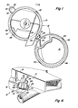
- Figs. 1-3 depict a vacuum seed meter 10 which has a generally cylindrical housing 12 which is comprised of a first half shell 14 and a mating second half shell 16.
- the half shells 14 and 16 are pivotally coupled to each other by a self-centering hinge 18 in accordance with the invention.
- the self-centering hinge 18 includes a spaced-apart pair of lugs 20 and 22 mounted on the first half shell 14 at the outer periphery thereof and a single lug 24 mounted on the outer periphery of the second half shell 16.
- the single lug 24 is pivotally coupled to the lugs 20 and 22 by a pin 26.
- a spring 28 is coupled to the pin 26 and to the first half shell 14 to provide the hinge 18 with resilient flexibility as described hereafter.
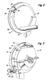
- the cylindrical housing 12 which is shown in the open position in Fig. 1 is shown in the closed position in Figs. 2 and 3.
- the cylindrical housing 12 is held in the closed position by a clasp 30 mounted at the outer periphery of the first half shell 14 opposite the hinge 18.
- the clasp 30 consists of a wire bracket 32 pivotally coupled to the first half shell 14 and having a roller 34 rotatably mounted at an intermediate portion of the wire bracket 32.
- the roller 34 is adapted to roll over and engage a lip 36 (shown in Fig. 2) formed adjacent the outer periphery of the second half shell 16 opposite the hinge 18 in order to latch the first half shell 14 to the second half shell 16.
- the first half shell 14 has a generally circular lip 38 at the outer periphery thereof.
- the lip 38 is formed with an upwardly extending flange 40 at a portion thereof opposite the hinge 18 and adjacent the clasp 30.
- the circular lip 38 is also formed with two additional flanges 42 and 44 at opposite sides thereof intermediate the hinge 18 and the clasp 30.
- the second half shell 16 is provided with a circular lip 46 formed with a flange 48 at a portion thereof opposite the hinge 18 and adjacent the lip 36 which receives the roller 34 of the clasp 30 when the cylindrical housing 12 is closed.
- the circular lip 46 of the second half shell 16 is also provided with flanges 50 and 52 at opposite sides thereof intermediate the hinge 18 and the flange 48.
- the flanges 40, 42, 44, 48, 50 and 52 are provided to aid in achieving alignment and proper fit of the second half shell 16 over the first half shell 14 when the cylindrical housing 12 is closed.
- the flanges 40, 42 and 44 on the circular lip 38 of the first half shell 14 are disposed slightly radially inwardly relative to the mating flanges 48, 50 and 52 on the circular lip 46 of the second half shell 16 so as to engage and fit within the flanges 48, 50 and 52 when the second half shell.16 is closed over the first half shell 14.
- the relatively precise fit provided by the flanges 40, 42, 44, 48, 50 and 52 is necessitated by the nature of the vacuum seed meter 10 and the fact that rather precise alignment and spacing of the half shells 14 and 16 is important to the proper operation of the seed disk (not shown) which is mounted at the interface between the half shells 14 and 16 and which must maintain rather precise spatial relationships with seals and other components within the cylindrical housing 12 including in particular a vacuum seal which bears against the side of the seed disk. Because of the rather precise and close fit of the flanges 48, 50 and 52 over the flanges 40, 42 and 44, it is important that the hinge 18 be self-centering.
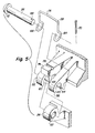
- the details of the self-centering hinge 18 are shown in Figs. 4-8. It was previously noted in connection with Fig. 1 that the pair of spaced-apart lugs 20 and 22 are mounted on the outer edge of the first half shell 14.
- the lug 20 has an opening therein in the form of a slot 54 at a first side 56 of the lug 20.
- the lug 22 has an opening therein in the form of a slot 58 at a first side 60 thereof...
- the first side 60 of the lug 22 faces in the same direction as the first side 56 of the lug 20.
- the slots 54 and 58 are adapated to receive opposite portions of the pin 26 therein.
- a central portion of the pin 26 resides within an opening in the form of a hole 62 in the lug 24 which is mounted on the second half shell 16.
- the spring 28 is of generally U-shaped configuration and is comprised of a length of resilient wire having loops 64 and 66 formed therein at the opposite ends thereof.
- the loop 64 is disposed adjacent the lug 20 opposite the lug 24 and encircles an end of the pin 26 just inside of a hole 68 in the pin 26.
- a cotter pin 70 disposed within the hole 68 on the opposite side of the loop 64 from the lug 20 holds the pin 26 in place.
- the end of the pin 26 opposite the hole 68 is provided with an enlarged head 72.
- the loop 66 of the spring 28 encircles the pin 26 at a portion of the pin 26 between the head 72 and the lug 22.
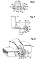
- the spring 28 is coupled between the pin 26 and the first half-shell 14. This coupling is accomplished by a mounting post 74 which is mounted on the first half shell 14 between the lugs 20 and 22 so as to be disposed adjacent the lug 24 on the opposite side of the pin 26 from the first sides 56 and 60 of the lugs 20 and 22.
- the spring 28 extends from the pin 26 in a direction opposite the first sides 56 and 60 so that an intermediate portion 76 of the spring 28 resides within a groove 78 in the mounting post 74.
- the slots 54 and 58 within the lugs 20 and 22 allow the pin 26 to move about rather freely therein to permit flexing of the hinge 18.
- the spring 28 normally holds the pin 26 under tension against the inner walls of the slots 54 and 58. However, if it becomes necessary to flex the hinge 18 so that the common central axis of the slots 54 and 58 forms an angle with rather than coinciding with the central axis of the hole 62 within the lug 24, then such motion is permitted by the slots 54 and 58 which are considerably larger than the outer diameter of the pin 26.
- the spring 28 tends to pull the pin 26 and the lug 24 which is mounted thereon toward the mounting post 74 which forms a part of the first half shell 14 so as to tend to keep the pin 26 seated within the slots 54 and 58.
- the mounting post 74 on the first half shell 14 is moved slightly upwardly or away from the lug 24 which is mounted on the second half shell 16 and which holds the pin 26 therein.
- This tension combines with the action of the clasp 30 at the opposite side of the cylindrical housing 12 to insure the close uniform contact that is desired around the entire circumference of the housing 12. It also eliminates at least half the slop or tolerance present in most hinges.
- the particular design of the hinge 18 enables limited movement of the second half shell 16 relative to the first half shell 14 in virtually any direction. This coupled with the resiliency of the spring 28 enables the hinge 18 to operate in self-centering fashion and to thereafter maintain close uniform contact between the opposite shells 14 and 16 as just described.
Landscapes
- Engineering & Computer Science (AREA)
- Mechanical Engineering (AREA)
- Pivots And Pivotal Connections (AREA)
- Hinge Accessories (AREA)
- Closing And Opening Devices For Wings, And Checks For Wings (AREA)
Applications Claiming Priority (2)
| Application Number | Priority Date | Filing Date | Title |
|---|---|---|---|
| US546833 | 1983-10-31 | ||
| US06/546,833 US4799291A (en) | 1983-10-31 | 1983-10-31 | Self-aligning hinge |
Publications (2)
| Publication Number | Publication Date |
|---|---|
| EP0140700A2 true EP0140700A2 (de) | 1985-05-08 |
| EP0140700A3 EP0140700A3 (de) | 1986-07-23 |
Family
ID=24182219
Family Applications (1)
| Application Number | Title | Priority Date | Filing Date |
|---|---|---|---|
| EP84307455A Withdrawn EP0140700A3 (de) | 1983-10-31 | 1984-10-29 | Selbstrichtendes Gelenk |
Country Status (8)
| Country | Link |
|---|---|
| US (1) | US4799291A (de) |
| EP (1) | EP0140700A3 (de) |
| AU (1) | AU3406584A (de) |
| BR (1) | BR8405537A (de) |
| CA (1) | CA1243814A (de) |
| DE (1) | DE140700T1 (de) |
| ES (1) | ES289619Y (de) |
| ZA (1) | ZA848461B (de) |
Cited By (1)
| Publication number | Priority date | Publication date | Assignee | Title |
|---|---|---|---|---|
| EP3042845A1 (de) * | 2015-01-08 | 2016-07-13 | Rohr, Inc. | Scharnierstruktur |
Families Citing this family (17)
| Publication number | Priority date | Publication date | Assignee | Title |
|---|---|---|---|---|
| US5839378A (en) * | 1996-08-20 | 1998-11-24 | Case Corporation | Agitator assembly for a seed metering mechanism |
| US5765720A (en) * | 1996-08-20 | 1998-06-16 | Case Corporation | Baffle assembly for a seed metering mechanism |
| US6109193A (en) | 1995-12-29 | 2000-08-29 | Case Corporation | Seed planter apparatus and method |
| US5848571A (en) * | 1996-08-20 | 1998-12-15 | Case Corporation | Seed singulator assembly for a seed metering mechanism |
| US5799598A (en) * | 1996-08-20 | 1998-09-01 | Case Corporation | Apparatus for sealing a vacuum chamber of a seed metering apparatus |
| US5740747A (en) * | 1996-08-20 | 1998-04-21 | Case Corporation | Vacuum seed metering assembly |
| US6564730B2 (en) * | 1995-12-29 | 2003-05-20 | Case Corporation | Seed planter apparatus and method |
| US5842428A (en) * | 1996-08-20 | 1998-12-01 | Case Corporation | Vacuum seed metering apparatus having housing openings |
| US6044779A (en) * | 1998-04-15 | 2000-04-04 | Case Corporation | Multiple drop seed disc |
| US6082352A (en) * | 1999-06-17 | 2000-07-04 | Lundar Electric Industrial Co., Ltd. | Oven door hinge |
| US6199548B1 (en) * | 1999-06-17 | 2001-03-13 | Lundar Electric Industrial Co., Ltd. | Structure of an oven |
| US6843300B2 (en) | 2003-03-21 | 2005-01-18 | Wayne-Dalton Corp. | Sectional door with self-aligning hinges and method of assembly |
| KR20070000673A (ko) * | 2005-06-28 | 2007-01-03 | 삼성전자주식회사 | 도어힌지장치 및 이를 갖춘 전자기기 |
| JP4394613B2 (ja) * | 2005-07-29 | 2010-01-06 | 本田技研工業株式会社 | 除雪機 |
| US7665186B2 (en) * | 2006-10-30 | 2010-02-23 | Sony Ericsson Mobile Communications Ab | Hinge with anti-skew features |
| DE102015105769A1 (de) * | 2015-04-15 | 2016-10-20 | Lemken Gmbh & Co. Kg | Mehrfachvereinzelungseinrichtung |
| US20240392602A1 (en) * | 2023-05-22 | 2024-11-28 | George Jiri Sterba | Garage door handle systems and apparatuses |
Family Cites Families (15)
| Publication number | Priority date | Publication date | Assignee | Title |
|---|---|---|---|---|
| GB211990A (en) * | 1922-12-08 | 1924-03-06 | John Edward Delbridge | Improvements in hinges |
| GB461575A (en) * | 1935-09-30 | 1937-02-19 | Charles Ebenezer Challis | Improvements relating to dishes provided with hinged covers |
| US2131802A (en) * | 1935-10-18 | 1938-10-04 | L C Smith & Corona Typewriters | Separable hinge connection |
| US2205969A (en) * | 1937-06-03 | 1940-06-25 | Boenecke Alfred | Hinge connection |
| US2429447A (en) * | 1944-08-01 | 1947-10-21 | Victor Metal Products Corp | Hinge |
| US2497337A (en) * | 1946-05-03 | 1950-02-14 | Duane S Ackerman | Awning hinge |
| US2538372A (en) * | 1947-06-18 | 1951-01-16 | David M Light | Antivibration device for journal box pins |
| US2656951A (en) * | 1948-03-19 | 1953-10-27 | Ferguson Harry Inc | Planter unit |
| US2975491A (en) * | 1958-09-18 | 1961-03-21 | Jacobs & Thompson Ltd | Frameless storm windows |
| US3406995A (en) * | 1966-07-13 | 1968-10-22 | Norco Inc | Releasable catch for equipment |
| US4153347A (en) * | 1977-06-08 | 1979-05-08 | Myer C Randolph | Eyeglass frames with removable, interchangeable lenses, rims and temple pieces |
| US4179844A (en) * | 1978-06-30 | 1979-12-25 | Young Windows Inc. | Hinge |
| US4343253A (en) * | 1979-05-23 | 1982-08-10 | The Singer Company | Lid and hinge arrangement for a convertible sewing machine |
| US4358871A (en) * | 1981-03-20 | 1982-11-16 | General Motors Corporation | Hook and pin hinged connection |
| GB2113291B (en) * | 1982-01-08 | 1985-04-11 | Avo Limited | Hinges |
-
1983
- 1983-10-31 US US06/546,833 patent/US4799291A/en not_active Expired - Fee Related
-
1984
- 1984-10-04 CA CA000464739A patent/CA1243814A/en not_active Expired
- 1984-10-09 AU AU34065/84A patent/AU3406584A/en not_active Abandoned
- 1984-10-29 DE DE198484307455T patent/DE140700T1/de active Pending
- 1984-10-29 EP EP84307455A patent/EP0140700A3/de not_active Withdrawn
- 1984-10-30 ES ES1984289619U patent/ES289619Y/es not_active Expired
- 1984-10-30 ZA ZA848461A patent/ZA848461B/xx unknown
- 1984-10-30 BR BR8405537A patent/BR8405537A/pt unknown
Cited By (1)
| Publication number | Priority date | Publication date | Assignee | Title |
|---|---|---|---|---|
| EP3042845A1 (de) * | 2015-01-08 | 2016-07-13 | Rohr, Inc. | Scharnierstruktur |
Also Published As
| Publication number | Publication date |
|---|---|
| EP0140700A3 (de) | 1986-07-23 |
| BR8405537A (pt) | 1985-09-10 |
| ES289619Y (es) | 1986-11-16 |
| ZA848461B (en) | 1986-06-25 |
| AU3406584A (en) | 1985-05-09 |
| US4799291A (en) | 1989-01-24 |
| CA1243814A (en) | 1988-11-01 |
| ES289619U (es) | 1986-04-01 |
| DE140700T1 (de) | 1985-10-10 |
Similar Documents
| Publication | Publication Date | Title |
|---|---|---|
| EP0140700A2 (de) | Selbstrichtendes Gelenk | |
| US5494245A (en) | Wiring harness retainer clip | |
| KR930011637B1 (ko) | 힌지(Hinge) | |
| US6168445B1 (en) | Two-part electrical connector | |
| US5319836A (en) | Buckle assembly | |
| US4588245A (en) | Self-locking coupling nut | |
| EP0926675A1 (de) | Magnetbandkassette | |
| US6073318A (en) | Retaining clip assembly | |
| US4544225A (en) | Connector latch | |
| JP3828701B2 (ja) | 燃料分配管への燃料噴射弁の取付け構造 | |
| GB2597960A (en) | Connector assembly with sealed symmetrical split lever | |
| US4701064A (en) | Ball joint | |
| KR20010033894A (ko) | 스웰 래치조립체 | |
| US4603566A (en) | Safety lock | |
| US5349510A (en) | Spring latching mechanism for light fixture | |
| US4096531A (en) | Deflection yoke | |
| JP2001083364A (ja) | オプティカルプラグとソケットを接続するためのプラグ部品 | |
| US5506909A (en) | Noise filtering device | |
| GB2219061A (en) | Fixing bundle of elongate members or an elongate element having a non-cylindrical outer surface to a support | |
| JPH0771157A (ja) | ヒンジ | |
| US5128714A (en) | Structure of a film holder | |
| JPS614677A (ja) | 特に自転車及び同種車両の変速機のチエ−ンガイド引張ア−ムの連結装置の組立用デバイス | |
| US4287641A (en) | Self-closing hinge | |
| WO1998008275A1 (en) | Locking strap for a plug-and-socket device | |
| JPH0740420B2 (ja) | デイスクカ−トリツジ |
Legal Events
| Date | Code | Title | Description |
|---|---|---|---|
| PUAI | Public reference made under article 153(3) epc to a published international application that has entered the european phase |
Free format text: ORIGINAL CODE: 0009012 |
|
| AK | Designated contracting states |
Designated state(s): DE FR GB |
|
| EL | Fr: translation of claims filed | ||
| DET | De: translation of patent claims | ||
| PUAL | Search report despatched |
Free format text: ORIGINAL CODE: 0009013 |
|
| AK | Designated contracting states |
Kind code of ref document: A3 Designated state(s): DE FR GB |
|
| 17P | Request for examination filed |
Effective date: 19860811 |
|
| STAA | Information on the status of an ep patent application or granted ep patent |
Free format text: STATUS: THE APPLICATION HAS BEEN WITHDRAWN |
|
| 18W | Application withdrawn |
Withdrawal date: 19861124 |
|
| RIN1 | Information on inventor provided before grant (corrected) |
Inventor name: OLSON, JAY HAROLD Inventor name: ANKUM, ROBERT HARPER |