EP0139336B1 - Method and device of forming a sleeve - Google Patents
Method and device of forming a sleeve Download PDFInfo
- Publication number
- EP0139336B1 EP0139336B1 EP84201495A EP84201495A EP0139336B1 EP 0139336 B1 EP0139336 B1 EP 0139336B1 EP 84201495 A EP84201495 A EP 84201495A EP 84201495 A EP84201495 A EP 84201495A EP 0139336 B1 EP0139336 B1 EP 0139336B1
- Authority
- EP
- European Patent Office
- Prior art keywords
- plate
- guideway
- plates
- mould wall
- sleeve
- Prior art date
- Legal status (The legal status is an assumption and is not a legal conclusion. Google has not performed a legal analysis and makes no representation as to the accuracy of the status listed.)
- Expired
Links
Images

Classifications
-
- B—PERFORMING OPERATIONS; TRANSPORTING
- B21—MECHANICAL METAL-WORKING WITHOUT ESSENTIALLY REMOVING MATERIAL; PUNCHING METAL
- B21D—WORKING OR PROCESSING OF SHEET METAL OR METAL TUBES, RODS OR PROFILES WITHOUT ESSENTIALLY REMOVING MATERIAL; PUNCHING METAL
- B21D51/00—Making hollow objects
- B21D51/02—Making hollow objects characterised by the structure of the objects
- B21D51/10—Making hollow objects characterised by the structure of the objects conically or cylindrically shaped objects
-
- B—PERFORMING OPERATIONS; TRANSPORTING
- B21—MECHANICAL METAL-WORKING WITHOUT ESSENTIALLY REMOVING MATERIAL; PUNCHING METAL
- B21D—WORKING OR PROCESSING OF SHEET METAL OR METAL TUBES, RODS OR PROFILES WITHOUT ESSENTIALLY REMOVING MATERIAL; PUNCHING METAL
- B21D51/00—Making hollow objects
- B21D51/16—Making hollow objects characterised by the use of the objects
- B21D51/54—Making hollow objects characterised by the use of the objects cartridge cases, e.g. for ammunition, for letter carriers in pneumatic-tube plants
Definitions
- the invention relates to a method of forming a sleeve of circular cross-section(s) from a flat plate of predetermined shape, according to which method the plate is pressed through a guideway enclosing the plate in its plane against and along a hollow mould wall having a shape corresponding to the shape of the sleeve to be formed.
- Such a method of and an apparatus for forming a sleeve are known from e.g. GB-A-248 719.
- the technique disclosed in this prior art specification implies the necessity of using reciprocating parts and pusher means for removing a formed cylindrical sleeve in the axial direction of an annular shaping channel.
- the invention proposes a method of the type described above, and which is characterized in that for forming a cylindrical sleeve a rectangular plate is pressed against and along a hollow mould wall of at most semi-cylindrical shape and that the plate to be deformed is pushed by the next-following plate out of the guideway against the mould wall.
- This method provides a fully continuous process to form sleeves obtained in an uninterrupted sequence from a series of plates one pushing on the other towards, against and along the mould wall. This complete continuity ensures a very low mechanical load and abrasion of the mould wall, which therefore has an extremely long lifetime.
- the mould wall is not repeatedly loaded shockwise, but it is loaded substantially fully continuously, so that owing to this substantially stationary load wear will be gradual and will not be concentrated at the place of entry.
- the method embodying the invention requires little power for manufacturing a sleeve. Moreover, with respect to the disposition of the various component parts and to the guidance of the plates to be deformed the construction of the device is considerably simpler.
- the method according to the invention provides a self-detaching effect of the formed sleeves. Therefore, no reciprocating parts are necessary.
- the inherent high production rate capabilities can be even further enhanced by using means for accelerating the delivery of the sleeves formed.
- the invention furthermore relates to a device for forming sleeves of circular cross-section from flat plates of predetermined shapes, comprising
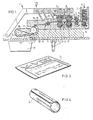
- Figure 1 shows a device 1 to form sleeves 4 from plates 3 contained in a stock holder 2.
- the plates 3 are removed from the stack of plates 3 in the holder 2 by means operating by subatmospheric pressure.
- the lowermost plate is carried at its edges by ridges 22. From this place they are transported further by transport rollers 6, 7 towards pairs of rollers 8, 9 and 10, 11 respectively, the centre-to-centre distance of which is slightly smaller than two lengths of the plates, i.e. the linear dimension of the plates in the transport direction. Due to the absence of lateral guidance beyond the rollers 8, 9 the required accuracy in positioning the plates is not ensured at the start of the device.
- a brake 12 which is a mechanical brake in the embodiment shown, but which may as well be of, for example, a magnetic or subatmospheric-pressure type.
- the ram 12 serves to bring a supplied plate to a full stop.
- the supplied plates 3 are guided through a gap-shaped guideway 13 enclosing the plates in their plane, said guideway having, downstream, with respect to the pair of rollers 10, 11, a part 14 of generally S-shaped form.
- a roller 25 In the inlet part of this slightly S-shaped part 14 is located a roller 25.
- the part 14 is a cracking station to improve the homogeneity of the physical properties of the sheet material.
- each supplied plate is pressed against and along a mould wall 16 having a shape matching the shape of the sleeves to be formed.
- the mould wall is slightly less than semi-cylindrical, that is to say, it covers an angle of less than 180° in the plane of the drawing. From the drawing it will be apparent that in this way a self-detaching effect is obtained for the sleeves 4 formed.
- a delivery transport roller 17 is used for accelerating the delivery.
- a rope 18 passes along the rollers 17, 19 and 23.
- FIG. 1 shows in detail the S-shaped guideway part 14 and the mould wall 16.
Landscapes
- Engineering & Computer Science (AREA)
- Mechanical Engineering (AREA)
- Making Paper Articles (AREA)
- Bending Of Plates, Rods, And Pipes (AREA)
- Extrusion Moulding Of Plastics Or The Like (AREA)
- Sealing Battery Cases Or Jackets (AREA)
- Forging (AREA)
Applications Claiming Priority (2)
| Application Number | Priority Date | Filing Date | Title |
|---|---|---|---|
| NL8303615A NL8303615A (nl) | 1983-10-20 | 1983-10-20 | Werkwijze en inrichting voor het vormen van een huls. |
| NL8303615 | 1983-10-20 |
Publications (3)
| Publication Number | Publication Date |
|---|---|
| EP0139336A2 EP0139336A2 (en) | 1985-05-02 |
| EP0139336A3 EP0139336A3 (en) | 1985-06-12 |
| EP0139336B1 true EP0139336B1 (en) | 1989-04-26 |
Family
ID=19842588
Family Applications (1)
| Application Number | Title | Priority Date | Filing Date |
|---|---|---|---|
| EP84201495A Expired EP0139336B1 (en) | 1983-10-20 | 1984-10-15 | Method and device of forming a sleeve |
Country Status (6)
| Country | Link |
|---|---|
| US (1) | US4682485A (da) |
| EP (1) | EP0139336B1 (da) |
| JP (1) | JPS60111731A (da) |
| DE (1) | DE3477893D1 (da) |
| DK (1) | DK488784A (da) |
| NL (1) | NL8303615A (da) |
Families Citing this family (2)
| Publication number | Priority date | Publication date | Assignee | Title |
|---|---|---|---|---|
| DE29601157U1 (de) * | 1995-11-28 | 1996-04-11 | Hoene, Jochen, 51702 Bergneustadt | Hülse zum Führen, Umlenken und Halten eines Nagels |
| JP2001523579A (ja) | 1997-11-17 | 2001-11-27 | コスマ インターナショナル インコーポレイテッド | 突起溶接パネルスペーサー及びその製造方法 |
Family Cites Families (10)
| Publication number | Priority date | Publication date | Assignee | Title |
|---|---|---|---|---|
| US735936A (en) * | 1901-11-01 | 1903-08-11 | George G Blakey | Manufacture of tubular articles. |
| GB248719A (en) * | 1925-03-06 | 1926-07-22 | Sachs Gmbh R | An improved contrivance for rolling cylindrical sheet zinc casings |
| US1936454A (en) * | 1928-11-05 | 1933-11-21 | Cleveland Graphite Bronze Co | Apparatus for making bearings |
| US2223599A (en) * | 1938-04-20 | 1940-12-03 | Cameron Can Machinery Co | Blank feeding and flexing mechanism |
| US2245407A (en) * | 1938-09-02 | 1941-06-10 | Gen Motors Corp | Apparatus for roll forming strip material |
| US2413594A (en) * | 1944-11-07 | 1946-12-31 | Wendell H White | Means for curling open-end drums |
| DE940526C (de) * | 1950-06-20 | 1956-03-22 | Rca Corp | Verfahren und Einrichtung zum Formen duenner Metallbleche zu einem Roehrchen |
| US3665744A (en) * | 1970-05-21 | 1972-05-30 | Clair M Harter | Method and apparatus for making sleeves |
| US3959066A (en) * | 1974-09-13 | 1976-05-25 | Polytube, Inc. | Apparatus for manufacturing the body portion of a collapsible squeeze tube |
| US4114550A (en) * | 1977-03-14 | 1978-09-19 | Toyo Seikan Kaisha, Ltd. | Apparatus for use in an automatic and continuous manufacture line for manufacturing the outer cylindrical cases of dry cells |
-
1983
- 1983-10-20 NL NL8303615A patent/NL8303615A/nl not_active Application Discontinuation
-
1984
- 1984-10-12 DK DK488784A patent/DK488784A/da not_active Application Discontinuation
- 1984-10-15 EP EP84201495A patent/EP0139336B1/en not_active Expired
- 1984-10-15 US US06/660,883 patent/US4682485A/en not_active Expired - Fee Related
- 1984-10-15 DE DE8484201495T patent/DE3477893D1/de not_active Expired
- 1984-10-19 JP JP59221129A patent/JPS60111731A/ja active Pending
Also Published As
| Publication number | Publication date |
|---|---|
| EP0139336A2 (en) | 1985-05-02 |
| US4682485A (en) | 1987-07-28 |
| DK488784A (da) | 1985-04-21 |
| NL8303615A (nl) | 1985-05-17 |
| JPS60111731A (ja) | 1985-06-18 |
| DE3477893D1 (en) | 1989-06-01 |
| DK488784D0 (da) | 1984-10-12 |
| EP0139336A3 (en) | 1985-06-12 |
Similar Documents
| Publication | Publication Date | Title |
|---|---|---|
| US4622835A (en) | Apparatus and method for continuously forming edgewise wound cores | |
| US3076492A (en) | Apparatus for removing the curl from sheets | |
| JPH01215420A (ja) | 截頭角錐状の缶胴を製造する方法と装置 | |
| ES8107114A1 (es) | Perfeccionamientos en dispositivos para apilar objetos pla- nos,particularmente piezas planas recortadas de cajas ple- gables | |
| US5918725A (en) | Machine for positioning and leveling plates for electric accumulators | |
| US3651921A (en) | Bar separator | |
| EP0139336B1 (en) | Method and device of forming a sleeve | |
| JPH06305552A (ja) | 傷つき易い小片製品を導入する方法とその装置 | |
| JPS5810329B2 (ja) | 無秩序に供給される細長い物品を整列させる装置 | |
| US2245407A (en) | Apparatus for roll forming strip material | |
| US3904097A (en) | Device for breaking away individual rolls from a roll of web or sheet material after the roll has been slit | |
| KR950024819A (ko) | 금속링제조장치 및 그 제조방법 | |
| US20240123485A1 (en) | Processing apparatus for rounding edge of lead tab for secondary battery | |
| US3340778A (en) | Apparatus for cutting, creasing, scoring, and the like | |
| CN105344759B (zh) | 一种加热管自动弯折装置 | |
| CN103537579A (zh) | 一种排料装置和一种管件接料送料装置 | |
| DE2306096A1 (de) | Bremsmittel in einer pneumatischen foerderleitung fuer filterstaebe | |
| GB2188261A (en) | Manufacture of a bead chain | |
| US2687163A (en) | Machine for reforming can bodies | |
| DE2815829C3 (de) | Vorrichtung zur Bildung einer Lücke in einem Strom von geschuppt übereinanderliegenden Werkstücken | |
| US4310032A (en) | Apparatus for making paper clips | |
| JPS62500559A (ja) | 切取り条片、鉄心、この鉄心を形成する方法と装置 | |
| US3529758A (en) | Device for aligning products of considerable length,more particularly hot-rolled products | |
| IT8222679A1 (it) | Vite trasportatrice per oggetti, come bottiglie sagomate | |
| KR101987901B1 (ko) | 피스톤링의 면취장치 |
Legal Events
| Date | Code | Title | Description |
|---|---|---|---|
| PUAI | Public reference made under article 153(3) epc to a published international application that has entered the european phase |
Free format text: ORIGINAL CODE: 0009012 |
|
| PUAL | Search report despatched |
Free format text: ORIGINAL CODE: 0009013 |
|
| AK | Designated contracting states |
Designated state(s): BE CH DE FR GB LI NL SE |
|
| AK | Designated contracting states |
Designated state(s): BE CH DE FR GB LI NL SE |
|
| 17P | Request for examination filed |
Effective date: 19851212 |
|
| 17Q | First examination report despatched |
Effective date: 19860828 |
|
| GRAA | (expected) grant |
Free format text: ORIGINAL CODE: 0009210 |
|
| AK | Designated contracting states |
Kind code of ref document: B1 Designated state(s): BE CH DE FR GB LI NL SE |
|
| REF | Corresponds to: |
Ref document number: 3477893 Country of ref document: DE Date of ref document: 19890601 |
|
| ET | Fr: translation filed | ||
| PG25 | Lapsed in a contracting state [announced via postgrant information from national office to epo] |
Ref country code: GB Effective date: 19891015 |
|
| PG25 | Lapsed in a contracting state [announced via postgrant information from national office to epo] |
Ref country code: SE Effective date: 19891016 |
|
| PG25 | Lapsed in a contracting state [announced via postgrant information from national office to epo] |
Ref country code: LI Effective date: 19891031 Ref country code: CH Effective date: 19891031 Ref country code: BE Effective date: 19891031 |
|
| PLBE | No opposition filed within time limit |
Free format text: ORIGINAL CODE: 0009261 |
|
| STAA | Information on the status of an ep patent application or granted ep patent |
Free format text: STATUS: NO OPPOSITION FILED WITHIN TIME LIMIT |
|
| 26N | No opposition filed | ||
| BERE | Be: lapsed |
Owner name: SOBEMI N.V. Effective date: 19891031 |
|
| PG25 | Lapsed in a contracting state [announced via postgrant information from national office to epo] |
Ref country code: NL Effective date: 19900501 |
|
| GBPC | Gb: european patent ceased through non-payment of renewal fee | ||
| NLV4 | Nl: lapsed or anulled due to non-payment of the annual fee | ||
| PG25 | Lapsed in a contracting state [announced via postgrant information from national office to epo] |
Ref country code: FR Effective date: 19900629 |
|
| REG | Reference to a national code |
Ref country code: CH Ref legal event code: PL |
|
| PG25 | Lapsed in a contracting state [announced via postgrant information from national office to epo] |
Ref country code: DE Effective date: 19900703 |
|
| REG | Reference to a national code |
Ref country code: FR Ref legal event code: ST |
|
| EUG | Se: european patent has lapsed |
Ref document number: 84201495.3 Effective date: 19900706 |