EP0139323B1 - Electron tube - Google Patents
Electron tube Download PDFInfo
- Publication number
- EP0139323B1 EP0139323B1 EP84201294A EP84201294A EP0139323B1 EP 0139323 B1 EP0139323 B1 EP 0139323B1 EP 84201294 A EP84201294 A EP 84201294A EP 84201294 A EP84201294 A EP 84201294A EP 0139323 B1 EP0139323 B1 EP 0139323B1
- Authority
- EP
- European Patent Office
- Prior art keywords
- spring
- electrode system
- electron tube
- wall
- spring element
- Prior art date
- Legal status (The legal status is an assumption and is not a legal conclusion. Google has not performed a legal analysis and makes no representation as to the accuracy of the status listed.)
- Expired
Links
- 239000011521 glass Substances 0.000 claims description 32
- 239000000463 material Substances 0.000 claims description 5
- 239000002184 metal Substances 0.000 claims description 5
- 229910052751 metal Inorganic materials 0.000 claims description 5
- 229910000570 Cupronickel Inorganic materials 0.000 claims description 3
- 229910045601 alloy Inorganic materials 0.000 claims description 3
- 239000000956 alloy Substances 0.000 claims description 3
- YOCUPQPZWBBYIX-UHFFFAOYSA-N copper nickel Chemical compound [Ni].[Cu] YOCUPQPZWBBYIX-UHFFFAOYSA-N 0.000 claims description 3
- 229910000831 Steel Inorganic materials 0.000 claims description 2
- VNNRSPGTAMTISX-UHFFFAOYSA-N chromium nickel Chemical compound [Cr].[Ni] VNNRSPGTAMTISX-UHFFFAOYSA-N 0.000 claims description 2
- 239000010959 steel Substances 0.000 claims description 2
- 238000010276 construction Methods 0.000 description 9
- 238000005452 bending Methods 0.000 description 5
- 239000002245 particle Substances 0.000 description 3
- 238000004519 manufacturing process Methods 0.000 description 2
- OKTJSMMVPCPJKN-UHFFFAOYSA-N Carbon Chemical compound [C] OKTJSMMVPCPJKN-UHFFFAOYSA-N 0.000 description 1
- 230000006835 compression Effects 0.000 description 1
- 238000007906 compression Methods 0.000 description 1
- 238000010894 electron beam technology Methods 0.000 description 1
- 229910002804 graphite Inorganic materials 0.000 description 1
- 239000010439 graphite Substances 0.000 description 1
- 238000005381 potential energy Methods 0.000 description 1
- 238000007788 roughening Methods 0.000 description 1
- 239000007779 soft material Substances 0.000 description 1
- 239000000126 substance Substances 0.000 description 1
Images
Classifications
-
- H—ELECTRICITY
- H01—ELECTRIC ELEMENTS
- H01J—ELECTRIC DISCHARGE TUBES OR DISCHARGE LAMPS
- H01J29/00—Details of cathode-ray tubes or of electron-beam tubes of the types covered by group H01J31/00
- H01J29/46—Arrangements of electrodes and associated parts for generating or controlling the ray or beam, e.g. electron-optical arrangement
- H01J29/82—Mounting, supporting, spacing, or insulating electron-optical or ion-optical arrangements
Definitions
- the invention relates to an electron tube having an electrode system slid in a tubular glass envelope portion and centred in the envelope portion by means of a number of metal spring elements which are connected to the electrode system, extend towards the wall of the envelope portion and which under pretension press against the wall of the envelope while forming a contact point.
- Such electron tubes are known in particular in the form of cathode-ray tubes, for example, picture display tubes and camera tubes as for example is described in DE-A-2262205.
- the electrode system forms therein an electron gun for generating one or more electron beams and during the manufacture of the tube it is inserted into the tubular envelope portion.
- the metal spring elements press against the glass wall of the envelope under pretension. Not infrequently damage in the form of scratches and crumbles glass particles occurs to the glass surface during sliding the spring elements over the glass wall.
- an electron tube having an electrode system slid in a tubular glass envelope portion and centred in the envelope portion by means of a number of metal spring elements which are connected to the electrode system, extend towards the wall of the envelope portion and which press against the wall of the envelope while forming a contact point is characterized in that the spring elements each extend over their effective spring length from a supporting point which is fixed with respect to the electrode system, according to a straight or substantially straight line which coincides or substantially coincides with the straight line which connects the said supporting point with the said contact point.
- “Fixed supporting point” is to be understood to mean herein a point which under pretension of the spring element assumes a fixed position with respect to the electrode system.
- the supporting point is the point where the effective or useful spring length begins.
- the supporting point is the point of impact of the resultant of the forces acting on the electrode system in a radial direction via a spring element.
- contact point it is to be noted that this usually is a contact area between the spring element and the tube wall. The contact point then is a point in the contact area where the largest pressure force prevails.
- the invention is based on the recognition of the fact that the cause of the occurrence of the above- mentioned glass damage is to be sought primarily in a variation of the bending moments occurring in the springs when the electrode system is inserted into the tubular envelope. As a result of this the free end of the springs periodically impacts forcefully against the glass wall. The force which is mainly responsible for the occurrence of said bending moments is the frictional force on the glass wall of the tube.
- the springs during sliding in the electrode system, are flexure-loaded. So during inserting, the springs will first bend without the contact point between spring and glass wall moving over the glass surface.
- the spring construction characterized according to the invention prevents the jerky movement of the spring because it extends substantially according to the straight connection line between the contact point with the glass wall and the supporting point on the electrode system from which the spring extends towards the glass wall.
- the varying play of forces between spring and glass then includes forces which in the longitudinal direction coincide with the spring, as a result of which the spring is no longer flexure-loaded.
- An embodiment of the invention is characterized in that the supporting point of a spring element coincides with a connection point of said spring element on the electrode system.
- the part of the spring extending over the effective spring length should be as straight as possible.
- the spring in the unloaded condition should have a curvature varying according to a third degree function (also termed third degree parabola).
- third degree parabola also termed third degree parabola.
- the measures suggested by the invention enable both the occurrence of scratches and the crumbling away of glass to be avoided to a considerable extent.
- Additional measures may consist according to the invention in that the surface of the spring element making contact with the tube wall comprises a layer of material having a smaller hardness than the hardness of the material of the spring element.
- the layer consists of a copper-nickel alloy and the spring element consists of chromium-nickel steel. Another possibility is to roughen the contacting surface of the spring chemically.
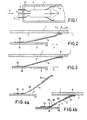
- Figure 1 shows a tubular glass envelope portion 1 of an electron tube not further shown.
- the said electron tube may be, for example, a picture display tube in which case the envelope portion 1 denotes the neck of the tube.
- a diagrammatically shown electrode system 3, mounted on a glass base 5 having electric connection pins 4, has been slid into the envelope portion in the direction of the arrow 2.
- the electrode system 3 comprises a number of metal centring springs 6 which press against the wall 7 of the envelope portion under pretension. The centring springs 6 centre the electrode system 3 with respect to the wall 7 and further serve to damp microphony or other vibrations to which the electrode system may be exposed during operation of the electron tube.
- the base 5 is sealed along its circumference with the tubular part 1 in the location denoted by 8 in the Figure.
- the springs 6 slide on the wall surface 7 which may be associated with scratches and crumbling away of glass. The occurrence of said glass damage will be described in detail with reference to a known spring construction as shown in Figure 2. For simplicity, corresponding components are referred to by the same reference numerals in the Figures.
- Point A represents the contact point between the spring 6 and the wall 7.
- Point B represents the connection point where the spring 6 is connected to the electrode system 3 by means of a spot weld 10. The part of the spring 6 present between the points A and B determines the effective length of the spring 6.
- the broken line 1 represents the elastic line of the spring, i.e. the line where the material of the spring is tension- free upon bending.
- the pressure force F r and the frictional force F f engage in the point A.
- the line AB does not coincide with the line 1, as a result of which the spring is flexure-loaded by a force resulting from the variable play of forces between spring and wall during the sliding movement, which force is directed according to the line AB.
- the stick-slip movement mentioned hereinbefore occurs which may be associated with glass damage.
- reversal of the direction of propagation 2 is no effective measure to avoid stick-slip movements. In that case, as a result of the non-coincidence of the lines AB and 1, the spring 6, during the sliding movement, will still be subject to a varying bending moment.
- Figure 3 shows diagrammatically a spring construction according to the invention.
- the point B forms a supporting point of the spring 6 which is fixed with respect to the electrode system 3.
- the part of the spring 6 between the spot weld 10 and the point B does not contribute to the effective spring length.
- the connection line AB coincides with the elastic line 1, so that, as compared with the Figure 2 situation, no bending moments occur here in the spring 6 but there is only a pure compression stress.
- This construction avoids a stick-slip movement.
- the spring 6 In the pretensioned condition the spring 6 should be as straight as possible over its effective spring length. Therefore, the spring 6, in the non-pretensioned condition, has a bent shape according to a third degree curve.
- Figures 4a and 4b show the spring in the non-pretensioned condition, while Figure 4b shows the spring 6 under pretension. At its free end the spring 6 has a spoon-line depression 21, the convex surface of which presses against the wall 7.
- a bend 20 has been provided in the spring 6. The strength of said bend 20 depends on the desired pretension which it is desired to achieve and on the distance between the electrode system 3 and the wall 7 to be bridged by the effective spring length. Instead of one bend, several bends may be provided with which a better approach of the parabolic variation can be achieved.
- Figure 4b shows that in the pretensioned condition the spring has arcuate parts 22 and 23 on each side of the bend 20.
- the elastic line 1 in these parts 22 and 23 also extends in the form of an arc. In some places the elastic line 1 will be above and in other places it will be below the connection line AB. This may be indicated by positive and negative deviations, respectively, of the elastic line 1 with respect to the line AB.
- the spring element is connected to the electrode system 3 by means of spot welds 10 and 11, the spot weld 11 coinciding with the supporting point B.
- the spoon-like part 21 is a comparatively rigid part of the spring.
- This convex surface may furthermore be coated with a layer of soft material, for example, a copper-nickel alloy or graphite. This measure provides an additional reduction of the possibility of the occurrence of glassdamage. The chemical roughening of the contacting surface of the spring results in reduced glass damage.
- the invention can be applied in all electron tubes in which an electrode system having centring springs is to be inserted into a tubular glass envelope portion. This applies notably to camera tubes and picture display tubes.
Landscapes
- Springs (AREA)
- Vessels, Lead-In Wires, Accessory Apparatuses For Cathode-Ray Tubes (AREA)
- Cathode-Ray Tubes And Fluorescent Screens For Display (AREA)
- Measuring Leads Or Probes (AREA)
Applications Claiming Priority (2)
| Application Number | Priority Date | Filing Date | Title |
|---|---|---|---|
| NL8303145 | 1983-09-12 | ||
| NL8303145A NL8303145A (nl) | 1983-09-12 | 1983-09-12 | Elektronenbuis. |
Publications (2)
| Publication Number | Publication Date |
|---|---|
| EP0139323A1 EP0139323A1 (en) | 1985-05-02 |
| EP0139323B1 true EP0139323B1 (en) | 1988-05-04 |
Family
ID=19842387
Family Applications (1)
| Application Number | Title | Priority Date | Filing Date |
|---|---|---|---|
| EP84201294A Expired EP0139323B1 (en) | 1983-09-12 | 1984-09-10 | Electron tube |
Country Status (8)
| Country | Link |
|---|---|
| US (1) | US5150002A (enExample) |
| EP (1) | EP0139323B1 (enExample) |
| JP (1) | JPS6077336A (enExample) |
| KR (1) | KR920001835B1 (enExample) |
| CA (1) | CA1225429A (enExample) |
| DE (1) | DE3470976D1 (enExample) |
| ES (1) | ES8506937A1 (enExample) |
| NL (1) | NL8303145A (enExample) |
Families Citing this family (7)
| Publication number | Priority date | Publication date | Assignee | Title |
|---|---|---|---|---|
| GB2180396A (en) * | 1985-09-11 | 1987-03-25 | Philips Electronic Associated | Flat cathode ray display tube |
| EP0562682B1 (en) * | 1992-03-27 | 1996-07-10 | Koninklijke Philips Electronics N.V. | Colour display tube having an electron gun |
| US5561347A (en) * | 1993-05-27 | 1996-10-01 | Hamamatsu Photonics K.K. | Photomultiplier |
| US5430350A (en) * | 1994-03-09 | 1995-07-04 | Chunghwa Picture Tubes, Ltd. | Electron gun support and positioning arrangement in a CRT |
| CA2976512A1 (en) | 2015-02-27 | 2016-09-01 | Kimberly-Clark Worldwide, Inc. | Absorbent article leakage assessment system |
| KR102099784B1 (ko) | 2017-04-05 | 2020-04-10 | 킴벌리-클라크 월드와이드, 인크. | 흡수 용품 누출 검출 의복 및 이를 이용한 흡수 용품 누출 검출 방법 |
| CN111306231A (zh) * | 2020-02-19 | 2020-06-19 | 西南交通大学 | 一种基于可恢复大变形超材料结构的隔振装置 |
Family Cites Families (19)
| Publication number | Priority date | Publication date | Assignee | Title |
|---|---|---|---|---|
| US2171766A (en) * | 1935-07-09 | 1939-09-05 | Firm Fernseh Ag | Means for fastening electrode systems in braun tubes |
| DE1026881B (de) * | 1955-06-30 | 1958-03-27 | Gen Electric | Verfahren und Anordnung zum axialsymmetrischen Einsetzen des oder der Strahlerzeugungssysteme in den Hals einer Kathodenstrahlroehre |
| US2828433A (en) * | 1956-04-25 | 1958-03-25 | Gen Dynamics Corp | Electron gun construction |
| US2991390A (en) * | 1959-04-01 | 1961-07-04 | Rca Corp | Shockproof mount |
| US3324336A (en) * | 1965-04-01 | 1967-06-06 | Sylvania Electric Prod | Vibration damping support spacers for electron gun mounts in cathode ray tubes |
| DE1810970A1 (de) * | 1968-11-26 | 1970-06-04 | Telefunken Patent | Elektronenroehre sowie Verfahren zu deren Herstellung |
| JPS4728439U (enExample) * | 1971-04-19 | 1972-12-01 | ||
| JPS4847260U (enExample) * | 1971-10-06 | 1973-06-21 | ||
| JPS4875162A (enExample) * | 1972-01-10 | 1973-10-09 | ||
| DE2262205C3 (de) * | 1972-12-19 | 1975-05-07 | Standard Elektrik Lorenz Ag, 7000 Stuttgart | Abstütz- und Zentriereinrichtung für Elektronenstrahlerzeugersysteme |
| JPS552702B2 (enExample) * | 1973-02-10 | 1980-01-22 | ||
| JPS5418127Y2 (enExample) * | 1973-07-14 | 1979-07-10 | ||
| JPS5434545Y2 (enExample) * | 1973-09-04 | 1979-10-22 | ||
| JPS51134367U (enExample) * | 1975-04-21 | 1976-10-29 | ||
| DE2720554A1 (de) * | 1977-05-07 | 1978-11-09 | Licentia Gmbh | Elektronenroehre |
| US4196371A (en) * | 1978-04-05 | 1980-04-01 | Tektronix, Inc. | Shock-absorbing means for mesh-carrying member of a cathode ray tube |
| JPS5717055U (enExample) * | 1980-07-02 | 1982-01-28 | ||
| US4368403A (en) * | 1980-07-09 | 1983-01-11 | The M-O Valve Company Limited | Electron gun including support structure for accelerating lens |
| JPS5732553A (en) * | 1980-08-04 | 1982-02-22 | Mitsubishi Electric Corp | Manufacture of cathode ray tube |
-
1983
- 1983-09-12 NL NL8303145A patent/NL8303145A/nl not_active Application Discontinuation
-
1984
- 1984-09-06 CA CA000462554A patent/CA1225429A/en not_active Expired
- 1984-09-08 JP JP59187294A patent/JPS6077336A/ja active Granted
- 1984-09-10 ES ES535793A patent/ES8506937A1/es not_active Expired
- 1984-09-10 EP EP84201294A patent/EP0139323B1/en not_active Expired
- 1984-09-10 DE DE8484201294T patent/DE3470976D1/de not_active Expired
- 1984-09-11 KR KR1019840005526A patent/KR920001835B1/ko not_active Expired
-
1989
- 1989-01-30 US US07/304,891 patent/US5150002A/en not_active Expired - Fee Related
Also Published As
| Publication number | Publication date |
|---|---|
| ES535793A0 (es) | 1985-08-01 |
| CA1225429A (en) | 1987-08-11 |
| KR920001835B1 (ko) | 1992-03-05 |
| EP0139323A1 (en) | 1985-05-02 |
| JPS6077336A (ja) | 1985-05-01 |
| ES8506937A1 (es) | 1985-08-01 |
| JPH0475621B2 (enExample) | 1992-12-01 |
| NL8303145A (nl) | 1985-04-01 |
| DE3470976D1 (en) | 1988-06-09 |
| US5150002A (en) | 1992-09-22 |
| KR850002663A (ko) | 1985-05-15 |
Similar Documents
| Publication | Publication Date | Title |
|---|---|---|
| EP0139323B1 (en) | Electron tube | |
| JPH10241604A (ja) | 陰極線管用ガラスパネル | |
| KR100345633B1 (ko) | 칼라 음극선관 | |
| US5672935A (en) | Supporting members for a color selecting electrode assembly | |
| US4754188A (en) | Color picture tube shadow mask material | |
| EP1059656A2 (en) | Cathode ray tube | |
| US4700105A (en) | Shadow mask mount for color picture tube | |
| US3573533A (en) | Gun-supporting cylinder centered in art neck by springs connected internally of cylinder | |
| US3062982A (en) | Electrode assembly support | |
| JPS5941264B2 (ja) | 陰極線管 | |
| JPS597726Y2 (ja) | 電子銃の支持装置 | |
| JPS6029161Y2 (ja) | 静電偏向形電子銃 | |
| JP3169772B2 (ja) | カラー陰極線管 | |
| EP1168411A1 (en) | Color selection mechanism for cathode ray tube and color cathode ray tube | |
| US20020024283A1 (en) | Shadow mask structure having shadow mask not undesirably vibrated | |
| JP3934435B2 (ja) | カラー陰極線管 | |
| KR100447653B1 (ko) | 칼라 음극선관용 마스크 어셈블리의 구조 | |
| JPH07335147A (ja) | 陰極線管 | |
| JP2846512B2 (ja) | カラー受像管のシャドウマスク | |
| JP3341676B2 (ja) | カラー陰極線管 | |
| US6628056B2 (en) | Mask assembly for cathode ray tube | |
| KR20030021694A (ko) | 브라운관의 섀도우 마스크 지지구조 | |
| JP2519285Y2 (ja) | カラー受像管 | |
| KR20020078625A (ko) | 음극선관의 마스크프레임 충격완화장치 | |
| JPH11204066A (ja) | ブラウン管用ゲッタースプリング |
Legal Events
| Date | Code | Title | Description |
|---|---|---|---|
| PUAI | Public reference made under article 153(3) epc to a published international application that has entered the european phase |
Free format text: ORIGINAL CODE: 0009012 |
|
| AK | Designated contracting states |
Designated state(s): DE FR GB IT NL |
|
| 17P | Request for examination filed |
Effective date: 19851021 |
|
| 17Q | First examination report despatched |
Effective date: 19861215 |
|
| GRAA | (expected) grant |
Free format text: ORIGINAL CODE: 0009210 |
|
| AK | Designated contracting states |
Kind code of ref document: B1 Designated state(s): DE FR GB IT NL |
|
| REF | Corresponds to: |
Ref document number: 3470976 Country of ref document: DE Date of ref document: 19880609 |
|
| ITF | It: translation for a ep patent filed | ||
| ET | Fr: translation filed | ||
| PLBE | No opposition filed within time limit |
Free format text: ORIGINAL CODE: 0009261 |
|
| STAA | Information on the status of an ep patent application or granted ep patent |
Free format text: STATUS: NO OPPOSITION FILED WITHIN TIME LIMIT |
|
| 26N | No opposition filed | ||
| PG25 | Lapsed in a contracting state [announced via postgrant information from national office to epo] |
Ref country code: NL Effective date: 19900401 |
|
| NLV4 | Nl: lapsed or anulled due to non-payment of the annual fee | ||
| ITTA | It: last paid annual fee | ||
| ITPR | It: changes in ownership of a european patent |
Owner name: CAMBIO RAGIONE SOCIALE;PHILIPS ELECTRONICS N.V. |
|
| REG | Reference to a national code |
Ref country code: FR Ref legal event code: CD |
|
| REG | Reference to a national code |
Ref country code: FR Ref legal event code: CD |
|
| PGFP | Annual fee paid to national office [announced via postgrant information from national office to epo] |
Ref country code: DE Payment date: 20001122 Year of fee payment: 17 |
|
| PGFP | Annual fee paid to national office [announced via postgrant information from national office to epo] |
Ref country code: FR Payment date: 20010925 Year of fee payment: 18 |
|
| PGFP | Annual fee paid to national office [announced via postgrant information from national office to epo] |
Ref country code: GB Payment date: 20011001 Year of fee payment: 18 |
|
| REG | Reference to a national code |
Ref country code: GB Ref legal event code: IF02 |
|
| PG25 | Lapsed in a contracting state [announced via postgrant information from national office to epo] |
Ref country code: DE Free format text: LAPSE BECAUSE OF NON-PAYMENT OF DUE FEES Effective date: 20020501 |
|
| PG25 | Lapsed in a contracting state [announced via postgrant information from national office to epo] |
Ref country code: GB Free format text: LAPSE BECAUSE OF NON-PAYMENT OF DUE FEES Effective date: 20020910 |
|
| GBPC | Gb: european patent ceased through non-payment of renewal fee |
Effective date: 20020910 |
|
| PG25 | Lapsed in a contracting state [announced via postgrant information from national office to epo] |
Ref country code: FR Free format text: LAPSE BECAUSE OF NON-PAYMENT OF DUE FEES Effective date: 20030603 |
|
| REG | Reference to a national code |
Ref country code: FR Ref legal event code: ST |