EP0138781A2 - Methode und Apparat zur Rauchgasreinigung - Google Patents
Methode und Apparat zur Rauchgasreinigung Download PDFInfo
- Publication number
- EP0138781A2 EP0138781A2 EP84850239A EP84850239A EP0138781A2 EP 0138781 A2 EP0138781 A2 EP 0138781A2 EP 84850239 A EP84850239 A EP 84850239A EP 84850239 A EP84850239 A EP 84850239A EP 0138781 A2 EP0138781 A2 EP 0138781A2
- Authority
- EP
- European Patent Office
- Prior art keywords
- water
- flue gases
- separation step
- vessel
- atomized
- Prior art date
- Legal status (The legal status is an assumption and is not a legal conclusion. Google has not performed a legal analysis and makes no representation as to the accuracy of the status listed.)
- Granted
Links
Images
Classifications
-
- B—PERFORMING OPERATIONS; TRANSPORTING
- B01—PHYSICAL OR CHEMICAL PROCESSES OR APPARATUS IN GENERAL
- B01D—SEPARATION
- B01D53/00—Separation of gases or vapours; Recovering vapours of volatile solvents from gases; Chemical or biological purification of waste gases, e.g. engine exhaust gases, smoke, fumes, flue gases, aerosols
- B01D53/34—Chemical or biological purification of waste gases
- B01D53/46—Removing components of defined structure
- B01D53/68—Halogens or halogen compounds
-
- B—PERFORMING OPERATIONS; TRANSPORTING
- B01—PHYSICAL OR CHEMICAL PROCESSES OR APPARATUS IN GENERAL
- B01D—SEPARATION
- B01D53/00—Separation of gases or vapours; Recovering vapours of volatile solvents from gases; Chemical or biological purification of waste gases, e.g. engine exhaust gases, smoke, fumes, flue gases, aerosols
- B01D53/34—Chemical or biological purification of waste gases
- B01D53/46—Removing components of defined structure
- B01D53/64—Heavy metals or compounds thereof, e.g. mercury
Definitions
- This invention relates to a method and an apparatus for the cleaning of flue gases, especially of flue gases containing compounds soluble in acid aqueous solutions.
- the present invention is intended particularly to be used for cleaning flue gases resulting from the combustion of household refuse, bulky waste, industrial waste or other fuel with a high water content, in respect of hydrocloric acid gas and heavy metals, such as mercury. Flue gases often are cleaned by using various types of mechanical filters and precipitators. More scarcely, such methods are combined with wet ones, at which the washing medium is supplied externally to the system as a separate material flow.
- the water inherent in the flue gas is utilized for cleaning the flue gases, thereby achieving the separation of water--soluble compounds. These compounds are concentrated in a later step by precipitation and thereafter are removed from the system.
- the present invention thus, relates to a method of flue--gas cleaning, comprising the separation of water-soluble substances from flue gases containing water vapour.
- the invention is characterized in that the flue gases are caused to cool by direct contact between flue gas and atomized water in two or more separation steps, and in a subsequent separation step in the flow direction of the flue gases the flue gases are cooled by atomized water to a temperature, at which the water in the flue gases is condensed out, which water is collected and thereafter both recycled for utilization in said subsequent separation step and introduced into a prior separation step in the flow direction of the flue gases, in which prior separation step the water is caused to be atomized and to meet uncleaned flue gases, the water--soluble and potentially water-soluble substances of which thereby are solved in the atomized water, and that the water thus impurified is collected for further treatment.
- the invention further relates to an apparatus for the cleaning of flue gases according to said method, which apparatus is of the type and has the main characterizing features as defined in the attached claim 5.
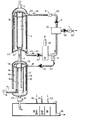
- a first separation step 1 and a second separation step 2 are shown, which are interconnected by a pipe 3.
- An inlet pipe 4 for flue gases is located in the lower portion of the first separation step, and an outlet pipe 5 for cleaned flue gases is located at the upper portion of the second separation step 2.
- the numerals 6,7,8 designate control valves
- the numerals 9 and 10 designate pumps
- 11 is a water and/or vapour seal
- 12 is a separation tank.
- the arrows in the Figure indicate flow directions.
- Flue gases 13 from a combustion plant are intended to be fed into the apparatus via the inlet pipe 4. Prior to their feed-in, the flue gases preferably are cooled in a cooler (not shown) to a temperature of 200-250°C. The flue gases thus fed-in rise through the first separation step 1.
- the first separation step 1 comprises a cylindric vessel, in which a tube system 14 is located.
- the tube system 14 comprises a plurality of substantially vertically arranged tubes 15, which are connected directly or indirectly to one or more feed pipes 16,17.
- Each tube 15, 16 is provided with a great number of apertures acting as spray nozzles for water. For reason of clearness, only a small number of apertures have been marked in the Figure by outflowing water 18.
- water is pumped by a pump 10 in the feed pipe 17 to the tube system 14 whereby atomized water flows out through said apertures.
- the upward flowing flue gas is hereby mixed effectively with water droplets.
- the second separation step 2 also comprises a cylindric vessel, in which a tube system 19 is located, which corresponds to the one described with reference to the first separation step.
- the tube system 19 has the same object and function. In operation it is supplied with water from a feed pipe 20 by means of a pump 9.
- the second separation step is formed at its lower end with an upward convex portion 21.
- the said pipe 3 connects the upper portion of the first separation step to the lower portion of the second separation step 2.
- the pipe 3 is connected to the highest point of the convex portion 21, and an annular cup 22 is formed in the lower portion of the second separation step.
- An outlet pipe 23 is connected at the bottom of said cup 22.
- a flow circuit for the second separation step 2 comprises - marked by the arrows 24 in the flow direction - the outlet pipe 23, a pump 37, a cooler 25 such as a heat pump, a possible device 26 for adjusting the pH--value of the water and the content of suspended substances, said pump 9, a control valve 6 and, finally, said feed pipe 20, which is connected to the tube system 19.
- the said feed pipe 17 to the tube system 14 of the first separation step 1 is connected to said flow circuit via a control valve 8.
- a discharge pipe 27 is located which opens into a tank 12 and is provided with a water and/or vapour seal.
- the tank 12 is provided with one or several sections or may consist of separate units connected in series for the neutralization and/or precipitation of different substances in the water coming from the lower separation step.
- the tank 12 is provided with one or more nozzles 30,31,32 or the like for adding chemicals for the precipitaion of desired substances and with means for stirring and mixing as well as for separating resulting precipitates.
- the object of the invention is to neutralize and/or separate water-soluble or potentially water-soluble substances from gases and flue gases with a high water vapour content.
- the separation of the substances is effected by cooling the gas or flue gas by direct contact between gas and atomized water in two or more separation steps connected in series.
- the necessary water amount is obtained by lowering the gas temperature to a desired level below its dew point.
- the second separation step 2 has the object primarily by cooling the gas to condense-out the water amount, which is desired in the first separation step 1. It is thereby possible to use simple structural material in the second separation step.
- the condensing-out of water from the gases proceeds in such a manner, that the gases are cooled by water flowing out of the tube system 19 to a temperature below the dew point at the pressure in question.
- an inlet temperature of e.g. 60-70°C and an outlet temperature of the gases of about 35°C are chosen.
- the separated water is circulated in said flow circuit.
- the water is cooled in the cooler 25, which preferably comprises a heat pump. Heated medium can pass out through a pipe 28.
- a device 26 not described in detail can be provided for adjusting the properties, for example the pH-value, of the water.
- the aforesaid valve 7 is used together with an associated pump 38 and a discharge pipe 29.
- the main part or all of the water which had been condensed out in the second separation step is passed via the valve 8 from the flow circuit to said feed pipe 17 and via the pump 10 to the tube system 14 of the first separation step 1,
- the valve 8 is located after the cooler 25, and therefore cooled water is caused to be atomized and sprayed via the system in the first separation step 1.
- incoming flue gases which have a temperature of e.g. 215-230°C, are cooled to the aforesaid temperature of 60-70 C, whereby the water in the gas to some part can be condensed out, and water-soluble substances are washed out of the gas.
- the part of the water which is not evaporated thereby, is removed from the system through the discharge pipe 27 to the tank 12.
- the apparatus and the method are especially suitably used for separating hydrochloric acid gas from flue gases and for substances forming complex difficultly volatile substances with chlorine.
- hydrochloric acid, HC1 gas and water-soluble mercury compounds and other water-soluble substances are solved and separated. Especially valuable is the separation of mercury out of flue gases from the combustion of e.g. household refuse.
- the cleaning in the first separation phas.e 1, of course, is not 100 per cent, but the second separation step 2 acts as final cleaning step as well as cooler.
- the contact between gas and liquid thus, is intended to take place in a combination of counter-current and cross-current apparatuses, where liquid is sprayed-in on different levels in the separation steps, whereby both a low pressure drop for the gas and a repeated drip formation with high washing-out effect are obtained.
- the process thus, is carried out with a relatively small amount of water. This is of advantage for the further treatment of the water enriched with impurities.
- the water collected in the tank system 12 is treated with chemicals, which are specific for the impurities desired to be separated from the water or be further treated.
- Lime (CaO) e.g. is added for neutralizing hydrochloric acid (HC1).
- HHC1 hydrochloric acid
- mercury is to be separated, for which purpose the water-soluble sulphide Na 2 S is added.
- CaO and Na S are added in a suitable way, for example through the nozzles 30,31,32.
- the present invention is not restricted to the separation of hydrochloric acid and mercury, which are of interest when household refuses are combusted, but every compound desired can be separated in the tank system 12 by adding known chemicals reacting with the substance to be separated. Precipitates resulting therefrom can be collected in different separate sections 33,34,35 in the tank system 12. Purified water can thereby be discharged through a discharge pipe 36.
- Resulting residue products such as precipitates, can thereafter be stored finally or be utilized for other purposes.
- the method and the apparatus render it possible to extremely effectively separate impurites in flue gases by using only the water contained in the flue gases. This implies, that the water collected has a high content of impurities, which facilitates their further treatment.
- the method and the apparatus are extremely simple to carry out and, respectively, to manufacture, so that the flue-gas cleaning costs can be kept very low compared to conventional art.
- the apparatus must be dimensioned according to the demand in respect of flue-gas volume and temperature, impurities to be separated, etc.
- the vertical tubes have a total of about 100 apertures with a diameter of 2,5 mm.
- the invention can be varied. Two or more series of separation steps can be connected in parallel, a certain amount of water be added externally, purification of separated water be introduced also in later separation steps, the vessel be positioned horizontally, etc. Such modifications are considered to be comprised in the invention in its widest scope.
Landscapes
- Engineering & Computer Science (AREA)
- Chemical & Material Sciences (AREA)
- Health & Medical Sciences (AREA)
- Biomedical Technology (AREA)
- Environmental & Geological Engineering (AREA)
- Analytical Chemistry (AREA)
- General Chemical & Material Sciences (AREA)
- Oil, Petroleum & Natural Gas (AREA)
- Chemical Kinetics & Catalysis (AREA)
- Treating Waste Gases (AREA)
- Paper (AREA)
- Sampling And Sample Adjustment (AREA)
Priority Applications (1)
| Application Number | Priority Date | Filing Date | Title |
|---|---|---|---|
| AT84850239T ATE57849T1 (de) | 1983-08-31 | 1984-08-09 | Methode und apparat zur rauchgasreinigung. |
Applications Claiming Priority (2)
| Application Number | Priority Date | Filing Date | Title |
|---|---|---|---|
| SE8304716 | 1983-08-31 | ||
| SE8304716A SE440608C (sv) | 1983-08-31 | 1983-08-31 | Foerfarande och anordning foer roekgasrening |
Publications (4)
| Publication Number | Publication Date |
|---|---|
| EP0138781A2 true EP0138781A2 (de) | 1985-04-24 |
| EP0138781A3 EP0138781A3 (en) | 1986-12-30 |
| EP0138781B1 EP0138781B1 (de) | 1990-10-31 |
| EP0138781B2 EP0138781B2 (de) | 1997-03-05 |
Family
ID=20352359
Family Applications (1)
| Application Number | Title | Priority Date | Filing Date |
|---|---|---|---|
| EP84850239A Expired - Lifetime EP0138781B2 (de) | 1983-08-31 | 1984-08-09 | Methode und Apparat zur Rauchgasreinigung |
Country Status (7)
| Country | Link |
|---|---|
| US (1) | US4583999A (de) |
| EP (1) | EP0138781B2 (de) |
| AT (1) | ATE57849T1 (de) |
| CA (1) | CA1245037A (de) |
| DE (1) | DE3483510D1 (de) |
| DK (1) | DK157662C (de) |
| SE (1) | SE440608C (de) |
Cited By (8)
| Publication number | Priority date | Publication date | Assignee | Title |
|---|---|---|---|---|
| DE3520885A1 (de) * | 1985-06-11 | 1986-12-11 | Kurt von Dipl.-Chem. Dr.rer.nat. 8170 Bad Tölz Beckerath | Verfahren und anlage zur weitgehenden restentfernung von schadstoffen aus abgasen von verbrennungsanlagen |
| WO1987003215A1 (fr) * | 1985-12-02 | 1987-06-04 | Propiorga | Procede et installation de neutralisation de fumees acides provenant notamment de la combustion de residus |
| EP0254697A1 (de) * | 1986-06-02 | 1988-01-27 | Erik Lindahl | Verfahren und Einrichtung für die Abtrennung von Quecksilber aus Rauchgasen und Prozessabgasen |
| EP0279003A1 (de) * | 1987-02-17 | 1988-08-24 | Herbert Küppenbender | Verfahren zur Rauch- und Abgasreinigung mittels Nassverfahren |
| EP0410336A1 (de) * | 1989-07-27 | 1991-01-30 | The Dow Chemical Company | Verfahren zur Reduktion von Emissionen von chlorierten Lösungsmitteln |
| FR2717249A1 (fr) * | 1994-03-14 | 1995-09-15 | Speic | Procédé et installation d'épuration de fumées issues d'un incinérateur à fusion et vitrification des déchets. |
| FR2717248A1 (fr) * | 1994-03-14 | 1995-09-15 | Speic | Procédé et installation d'épuration de fumées. |
| EP0864352A2 (de) * | 1997-03-10 | 1998-09-16 | Deutsches Zentrum für Luft- und Raumfahrt e.V. | Verfahren zur Reinigung eines Abgases einer Feuerungsanlage |
Families Citing this family (24)
| Publication number | Priority date | Publication date | Assignee | Title |
|---|---|---|---|---|
| DE3721056A1 (de) * | 1987-06-26 | 1989-01-05 | Bayer Ag | Verfahren zum aufheizen feuchter gase |
| US5156819A (en) * | 1988-04-20 | 1992-10-20 | Ross Jody D | Steam scrubbing system for exhaust gases |
| FR2655564B1 (fr) * | 1989-12-08 | 1992-06-19 | Sogea | Procede et dispositif de reduction de la teneur en gaz polluants acides de fumees issues d'un dispositif d'incineration. |
| KR950005498B1 (ko) * | 1992-03-13 | 1995-05-24 | 이대성 | 샤워터널식 배기가스 정화장치 |
| CZ284838B6 (cs) * | 1992-03-18 | 1999-03-17 | ABB Fläkt AB | Způsob a zařízení pro čištění nebo chlazení plynu |
| DE4304192A1 (de) * | 1993-02-12 | 1994-08-18 | Noell Gmbh | Verfahren zum Auswaschen der sauren Gaskomponenten aus Rauchgasen durch Absorption |
| DE4304191A1 (de) * | 1993-02-12 | 1994-08-18 | Noell Gmbh | Verfahren zum Auswaschen von sauren Gaskomponenten aus Rauchgasen durch Absorption |
| DE4304193C1 (de) * | 1993-02-12 | 1994-05-05 | Noell Gmbh | Verfahren zum Auswaschen der sauren Gaskomponenten aus Rauchgasen durch Absorption |
| SE9300962L (sv) * | 1993-03-23 | 1994-08-22 | Lennart Granstrand | Förfarande och anordning för rening och utvinning av energi ur varm gas |
| JP2912145B2 (ja) * | 1993-11-16 | 1999-06-28 | 住友重機械工業株式会社 | 硫黄酸化物含有ガスの浄化方法 |
| US6797178B2 (en) * | 2000-03-24 | 2004-09-28 | Ada Technologies, Inc. | Method for removing mercury and mercuric compounds from dental effluents |
| AU2002219907A1 (en) | 2000-11-28 | 2002-06-11 | Ada Technologies, Inc. | Improved method for fixating sludges and soils contaminated with mercury and other heavy metals |
| US7048781B1 (en) | 2002-10-07 | 2006-05-23 | Ada Technologies, Inc. | Chemically-impregnated silicate agents for mercury control |
| US6942840B1 (en) * | 2001-09-24 | 2005-09-13 | Ada Technologies, Inc. | Method for removal and stabilization of mercury in mercury-containing gas streams |
| GB0207284D0 (en) * | 2002-03-27 | 2002-05-08 | Boc Group Plc | Semiconductor exhaust gas treatment |
| US7183235B2 (en) * | 2002-06-21 | 2007-02-27 | Ada Technologies, Inc. | High capacity regenerable sorbent for removing arsenic and other toxic ions from drinking water |
| US7361209B1 (en) | 2003-04-03 | 2008-04-22 | Ada Environmental Solutions, Llc | Apparatus and process for preparing sorbents for mercury control at the point of use |
| WO2005032394A2 (en) * | 2003-10-01 | 2005-04-14 | Ada Technologies, Inc. | System for removing mercury and mercuric compounds from dental wastes |
| FR2861318B1 (fr) * | 2003-10-23 | 2006-01-06 | Air Liquide | Procede de lavage et de refroidissement d'un gaz par contact direct avec de l'eau et installation pour la mise en oeuvre du procede |
| FR2884731B1 (fr) * | 2005-04-20 | 2007-06-29 | Air Liquide | Procede d'epuration et de refroidissement de dioxyde de carbone avec reutilisation du condensat et installation pour la mise en oeuvre du procede |
| JP4173169B2 (ja) * | 2006-04-20 | 2008-10-29 | 英治 村田 | 有害物質除去装置および有害物質との接触促進を行うための筒ユニット |
| CA2751198A1 (en) * | 2009-02-03 | 2010-08-12 | Siemens Aktiengesellschaft | Process and apparatus for controlling a carbon monoxide emission of an electric arc furnace |
| US8640656B1 (en) * | 2010-02-27 | 2014-02-04 | Woody Vouth Vann | Self-sustaining boiler system |
| US9364781B2 (en) | 2013-10-11 | 2016-06-14 | Alstom Technology Ltd | Method and apparatus for wet desulfurization spray towers |
Citations (4)
| Publication number | Priority date | Publication date | Assignee | Title |
|---|---|---|---|---|
| US3841060A (en) * | 1973-04-27 | 1974-10-15 | Hoad Eng Inc | Gas washer apparatus |
| FR2283719A1 (fr) * | 1974-09-04 | 1976-04-02 | Seitetsu Kagaku Co Ltd | Procede de traitement des gaz d'echappement d'un foyer |
| DE2708919A1 (de) * | 1977-03-02 | 1978-09-07 | Otto & Co Gmbh Dr C | Verfahren zur reinigung von industrieabgasen |
| DE2449057B2 (de) * | 1973-10-16 | 1980-07-10 | Nippon Electric Co., Ltd., Tokio | Verfahren zur Reinigung von schwermetall- und giftmetallhaltigen Abgasen |
Family Cites Families (10)
| Publication number | Priority date | Publication date | Assignee | Title |
|---|---|---|---|---|
| US2598116A (en) * | 1948-05-07 | 1952-05-27 | Paper Patents Co | Process for cooling sulfur burner gas |
| US3022148A (en) * | 1958-11-18 | 1962-02-20 | Chemical Construction Corp | Oil quench process for partial oxidation of hydrocarbon gases |
| US3020138A (en) * | 1959-05-06 | 1962-02-06 | Allied Chem | Method for processing, distribution and combustion of coke-oven gas containing ammonia |
| US3073092A (en) * | 1959-12-28 | 1963-01-15 | British Titan Products | Cooling of vapour-phase oxidation products |
| DE1241804B (de) * | 1964-02-25 | 1967-06-08 | Metallgesellschaft Ag | Vorrichtung zur Nassbehandlung staubhaltiger Gase |
| US3691731A (en) * | 1970-07-13 | 1972-09-19 | Bernabe V Garcia | Smoke cleaning device |
| US3788331A (en) * | 1972-06-26 | 1974-01-29 | Reynolds Tobacco Co R | Solvent recovery in tobacco treating process |
| NL7304868A (de) * | 1973-04-06 | 1974-10-08 | ||
| DE2631444A1 (de) * | 1975-08-12 | 1977-02-24 | Lee Joseph Duvall | Verfahren und vorrichtung zur entfernung und rueckgewinnung von schwefeldioxid aus abgasen |
| US4239511A (en) * | 1978-12-14 | 1980-12-16 | Krupp-Koppers Gmbh | Process and apparatus for cooling coke oven gas |
-
1983
- 1983-08-31 SE SE8304716A patent/SE440608C/sv not_active IP Right Cessation
-
1984
- 1984-08-09 DE DE8484850239T patent/DE3483510D1/de not_active Expired - Lifetime
- 1984-08-09 EP EP84850239A patent/EP0138781B2/de not_active Expired - Lifetime
- 1984-08-09 AT AT84850239T patent/ATE57849T1/de not_active IP Right Cessation
- 1984-08-15 US US06/641,001 patent/US4583999A/en not_active Expired - Lifetime
- 1984-08-17 CA CA000461315A patent/CA1245037A/en not_active Expired
- 1984-08-30 DK DK415784A patent/DK157662C/da active
Patent Citations (4)
| Publication number | Priority date | Publication date | Assignee | Title |
|---|---|---|---|---|
| US3841060A (en) * | 1973-04-27 | 1974-10-15 | Hoad Eng Inc | Gas washer apparatus |
| DE2449057B2 (de) * | 1973-10-16 | 1980-07-10 | Nippon Electric Co., Ltd., Tokio | Verfahren zur Reinigung von schwermetall- und giftmetallhaltigen Abgasen |
| FR2283719A1 (fr) * | 1974-09-04 | 1976-04-02 | Seitetsu Kagaku Co Ltd | Procede de traitement des gaz d'echappement d'un foyer |
| DE2708919A1 (de) * | 1977-03-02 | 1978-09-07 | Otto & Co Gmbh Dr C | Verfahren zur reinigung von industrieabgasen |
Cited By (11)
| Publication number | Priority date | Publication date | Assignee | Title |
|---|---|---|---|---|
| DE3520885A1 (de) * | 1985-06-11 | 1986-12-11 | Kurt von Dipl.-Chem. Dr.rer.nat. 8170 Bad Tölz Beckerath | Verfahren und anlage zur weitgehenden restentfernung von schadstoffen aus abgasen von verbrennungsanlagen |
| WO1987003215A1 (fr) * | 1985-12-02 | 1987-06-04 | Propiorga | Procede et installation de neutralisation de fumees acides provenant notamment de la combustion de residus |
| FR2590805A1 (fr) * | 1985-12-02 | 1987-06-05 | Propiorga | Procede et installation de neutralisation de fumees acides provenant notamment de la combustion de residus |
| US4768448A (en) * | 1985-12-02 | 1988-09-06 | Propiorga | Method and plant for neutralizing acid smokes issued particularly from the combustion of residues |
| EP0254697A1 (de) * | 1986-06-02 | 1988-01-27 | Erik Lindahl | Verfahren und Einrichtung für die Abtrennung von Quecksilber aus Rauchgasen und Prozessabgasen |
| EP0279003A1 (de) * | 1987-02-17 | 1988-08-24 | Herbert Küppenbender | Verfahren zur Rauch- und Abgasreinigung mittels Nassverfahren |
| EP0410336A1 (de) * | 1989-07-27 | 1991-01-30 | The Dow Chemical Company | Verfahren zur Reduktion von Emissionen von chlorierten Lösungsmitteln |
| FR2717249A1 (fr) * | 1994-03-14 | 1995-09-15 | Speic | Procédé et installation d'épuration de fumées issues d'un incinérateur à fusion et vitrification des déchets. |
| FR2717248A1 (fr) * | 1994-03-14 | 1995-09-15 | Speic | Procédé et installation d'épuration de fumées. |
| EP0864352A2 (de) * | 1997-03-10 | 1998-09-16 | Deutsches Zentrum für Luft- und Raumfahrt e.V. | Verfahren zur Reinigung eines Abgases einer Feuerungsanlage |
| EP0864352A3 (de) * | 1997-03-10 | 1999-01-07 | Deutsches Zentrum für Luft- und Raumfahrt e.V. | Verfahren zur Reinigung eines Abgases einer Feuerungsanlage |
Also Published As
| Publication number | Publication date |
|---|---|
| SE8304716L (sv) | 1985-03-01 |
| DK157662B (da) | 1990-02-05 |
| SE440608B (sv) | 1985-08-12 |
| DK415784A (da) | 1985-03-01 |
| DK415784D0 (da) | 1984-08-30 |
| EP0138781B2 (de) | 1997-03-05 |
| SE8304716D0 (sv) | 1983-08-31 |
| EP0138781B1 (de) | 1990-10-31 |
| DK157662C (da) | 1995-10-30 |
| SE440608C (sv) | 1989-04-06 |
| CA1245037A (en) | 1988-11-22 |
| EP0138781A3 (en) | 1986-12-30 |
| DE3483510D1 (de) | 1990-12-06 |
| US4583999A (en) | 1986-04-22 |
| ATE57849T1 (de) | 1990-11-15 |
Similar Documents
| Publication | Publication Date | Title |
|---|---|---|
| US4583999A (en) | Method and apparatus for flue-gas cleaning | |
| US4312646A (en) | Gas scrubbing tower | |
| RU2459655C2 (ru) | Устройство и способ очистки дымовых газов | |
| US4279693A (en) | Process for purifying polluted fluids | |
| EA001995B1 (ru) | Скруббер для очистки дымовых газов | |
| EP2630292B1 (de) | Verfahren und anordnung zur entfernung von verunreinigungen aus flüssigkeiten oder gasen | |
| GB2037611A (en) | Gas scrubbing tower | |
| PL166456B1 (pl) | Sposób oczyszczania odcieku pochodzacego z wytwórni mocznika PL PL PL PL PL | |
| US3616597A (en) | Method for treating and purifying air | |
| CN105879582B (zh) | 一种用于二氧化碳捕集的多污染物治理设备及方法 | |
| CN112093834A (zh) | 含盐废水的分盐处理系统及处理方法 | |
| US4487748A (en) | Process for treating exhaust gases | |
| CA2195298C (en) | Method and apparatus for cleaning a vapour | |
| DE3916705A1 (de) | Verfahren zur rueckgewinnung der waerme von rauchgasen | |
| US2500774A (en) | Water treating method and apparatus | |
| CN1104755A (zh) | 利用火力发电厂的烟气余热的方法和装置 | |
| KR101977782B1 (ko) | 탈황탑에서 배출되는 폐수 처리장치 및 처리방법 | |
| JPH0679131A (ja) | 汚染された蒸気と空気との混合物の処理方法及びその装置 | |
| CN209618919U (zh) | 一种废水脱盐脱溶装置 | |
| US363952A (en) | Process of and apparatus for making sodium carbonate by ammonia | |
| US2028318A (en) | Purification of gases | |
| EP0245814B1 (de) | Einrichtung zur Kühlung und zur Eliminierung von Feuchtigkeit, Naphtha und Tar von Kohlendestillationsgasen | |
| CN217838625U (zh) | 一种焦炉煤气hpf脱硫废液硫泡沫再生处理系统 | |
| US3376102A (en) | Method of removing volatile acids from vapors in the manufacture of sulphate cellulose | |
| KR20010101436A (ko) | 폐수 정화방법 및 장치 |
Legal Events
| Date | Code | Title | Description |
|---|---|---|---|
| PUAI | Public reference made under article 153(3) epc to a published international application that has entered the european phase |
Free format text: ORIGINAL CODE: 0009012 |
|
| AK | Designated contracting states |
Designated state(s): AT CH DE FR GB IT LI LU NL |
|
| 17P | Request for examination filed |
Effective date: 19860627 |
|
| PUAL | Search report despatched |
Free format text: ORIGINAL CODE: 0009013 |
|
| AK | Designated contracting states |
Kind code of ref document: A3 Designated state(s): AT CH DE FR GB IT LI LU NL |
|
| 17Q | First examination report despatched |
Effective date: 19871222 |
|
| ITF | It: translation for a ep patent filed |
Owner name: BARZANO' E ZANARDO ROMA S.P.A. |
|
| GRAA | (expected) grant |
Free format text: ORIGINAL CODE: 0009210 |
|
| AK | Designated contracting states |
Kind code of ref document: B1 Designated state(s): AT CH DE FR GB IT LI LU NL |
|
| REF | Corresponds to: |
Ref document number: 57849 Country of ref document: AT Date of ref document: 19901115 Kind code of ref document: T |
|
| ET | Fr: translation filed | ||
| REF | Corresponds to: |
Ref document number: 3483510 Country of ref document: DE Date of ref document: 19901206 |
|
| PLBI | Opposition filed |
Free format text: ORIGINAL CODE: 0009260 |
|
| 26 | Opposition filed |
Opponent name: ABB FLAEKT AKTIEBOLAG Effective date: 19910731 |
|
| NLR1 | Nl: opposition has been filed with the epo |
Opponent name: ABB FLAEKT AKTIEBOLAG |
|
| REG | Reference to a national code |
Ref country code: FR Ref legal event code: ST |
|
| ITTA | It: last paid annual fee | ||
| REG | Reference to a national code |
Ref country code: FR Ref legal event code: AR |
|
| REG | Reference to a national code |
Ref country code: FR Ref legal event code: D1 |
|
| EPTA | Lu: last paid annual fee | ||
| PLAW | Interlocutory decision in opposition |
Free format text: ORIGINAL CODE: EPIDOS IDOP |
|
| APAC | Appeal dossier modified |
Free format text: ORIGINAL CODE: EPIDOS NOAPO |
|
| APAC | Appeal dossier modified |
Free format text: ORIGINAL CODE: EPIDOS NOAPO |
|
| PUAH | Patent maintained in amended form |
Free format text: ORIGINAL CODE: 0009272 |
|
| STAA | Information on the status of an ep patent application or granted ep patent |
Free format text: STATUS: PATENT MAINTAINED AS AMENDED |
|
| 27A | Patent maintained in amended form |
Effective date: 19970305 |
|
| AK | Designated contracting states |
Kind code of ref document: B2 Designated state(s): AT CH DE FR GB IT LI LU NL |
|
| REG | Reference to a national code |
Ref country code: CH Ref legal event code: AEN Free format text: AUFRECHTERHALTUNG DES PATENTES IN GEAENDERTER FORM |
|
| ET3 | Fr: translation filed ** decision concerning opposition | ||
| NLR2 | Nl: decision of opposition | ||
| NLR3 | Nl: receipt of modified translations in the netherlands language after an opposition procedure | ||
| PGFP | Annual fee paid to national office [announced via postgrant information from national office to epo] |
Ref country code: LU Payment date: 19970707 Year of fee payment: 14 |
|
| PG25 | Lapsed in a contracting state [announced via postgrant information from national office to epo] |
Ref country code: LU Free format text: LAPSE BECAUSE OF NON-PAYMENT OF DUE FEES Effective date: 19980809 |
|
| PGFP | Annual fee paid to national office [announced via postgrant information from national office to epo] |
Ref country code: GB Payment date: 19990716 Year of fee payment: 16 |
|
| PGFP | Annual fee paid to national office [announced via postgrant information from national office to epo] |
Ref country code: FR Payment date: 19990806 Year of fee payment: 16 |
|
| PGFP | Annual fee paid to national office [announced via postgrant information from national office to epo] |
Ref country code: AT Payment date: 19990818 Year of fee payment: 16 |
|
| PGFP | Annual fee paid to national office [announced via postgrant information from national office to epo] |
Ref country code: DE Payment date: 19990823 Year of fee payment: 16 |
|
| PGFP | Annual fee paid to national office [announced via postgrant information from national office to epo] |
Ref country code: CH Payment date: 19990824 Year of fee payment: 16 |
|
| PGFP | Annual fee paid to national office [announced via postgrant information from national office to epo] |
Ref country code: NL Payment date: 19990830 Year of fee payment: 16 |
|
| PG25 | Lapsed in a contracting state [announced via postgrant information from national office to epo] |
Ref country code: GB Free format text: LAPSE BECAUSE OF NON-PAYMENT OF DUE FEES Effective date: 20000809 Ref country code: AT Free format text: LAPSE BECAUSE OF NON-PAYMENT OF DUE FEES Effective date: 20000809 |
|
| PG25 | Lapsed in a contracting state [announced via postgrant information from national office to epo] |
Ref country code: LI Free format text: LAPSE BECAUSE OF NON-PAYMENT OF DUE FEES Effective date: 20000831 Ref country code: CH Free format text: LAPSE BECAUSE OF NON-PAYMENT OF DUE FEES Effective date: 20000831 |
|
| PG25 | Lapsed in a contracting state [announced via postgrant information from national office to epo] |
Ref country code: NL Free format text: LAPSE BECAUSE OF NON-PAYMENT OF DUE FEES Effective date: 20010301 |
|
| GBPC | Gb: european patent ceased through non-payment of renewal fee |
Effective date: 20000809 |
|
| REG | Reference to a national code |
Ref country code: CH Ref legal event code: PL |
|
| PG25 | Lapsed in a contracting state [announced via postgrant information from national office to epo] |
Ref country code: FR Free format text: LAPSE BECAUSE OF NON-PAYMENT OF DUE FEES Effective date: 20010430 |
|
| NLV4 | Nl: lapsed or anulled due to non-payment of the annual fee |
Effective date: 20010301 |
|
| PG25 | Lapsed in a contracting state [announced via postgrant information from national office to epo] |
Ref country code: DE Free format text: LAPSE BECAUSE OF NON-PAYMENT OF DUE FEES Effective date: 20010501 |
|
| REG | Reference to a national code |
Ref country code: FR Ref legal event code: ST |
|
| APAH | Appeal reference modified |
Free format text: ORIGINAL CODE: EPIDOSCREFNO |