EP0864352A2 - Verfahren zur Reinigung eines Abgases einer Feuerungsanlage - Google Patents
Verfahren zur Reinigung eines Abgases einer Feuerungsanlage Download PDFInfo
- Publication number
- EP0864352A2 EP0864352A2 EP98103856A EP98103856A EP0864352A2 EP 0864352 A2 EP0864352 A2 EP 0864352A2 EP 98103856 A EP98103856 A EP 98103856A EP 98103856 A EP98103856 A EP 98103856A EP 0864352 A2 EP0864352 A2 EP 0864352A2
- Authority
- EP
- European Patent Office
- Prior art keywords
- medium
- intermediate carrier
- exhaust gas
- carrier medium
- neutralizing agent
- Prior art date
- Legal status (The legal status is an assumption and is not a legal conclusion. Google has not performed a legal analysis and makes no representation as to the accuracy of the status listed.)
- Withdrawn
Links
- 238000000034 method Methods 0.000 title claims abstract description 48
- 238000004140 cleaning Methods 0.000 title claims description 33
- 238000002485 combustion reaction Methods 0.000 title claims description 8
- 239000003795 chemical substances by application Substances 0.000 claims abstract description 105
- 238000006386 neutralization reaction Methods 0.000 claims abstract description 24
- 150000004706 metal oxides Chemical group 0.000 claims abstract description 8
- 229910044991 metal oxide Inorganic materials 0.000 claims abstract description 7
- 239000003513 alkali Substances 0.000 claims abstract description 6
- 230000003472 neutralizing effect Effects 0.000 claims description 108
- 238000000746 purification Methods 0.000 claims description 54
- 239000007788 liquid Substances 0.000 claims description 52
- 239000008236 heating water Substances 0.000 claims description 22
- 230000005484 gravity Effects 0.000 claims description 20
- 239000008187 granular material Substances 0.000 claims description 10
- 238000010438 heat treatment Methods 0.000 claims description 10
- XLYOFNOQVPJJNP-UHFFFAOYSA-N water Substances O XLYOFNOQVPJJNP-UHFFFAOYSA-N 0.000 claims description 10
- 229910000287 alkaline earth metal oxide Inorganic materials 0.000 claims description 9
- 238000006477 desulfuration reaction Methods 0.000 claims description 8
- 230000023556 desulfurization Effects 0.000 claims description 8
- 238000010304 firing Methods 0.000 claims description 4
- 230000009969 flowable effect Effects 0.000 claims description 2
- 238000009736 wetting Methods 0.000 claims 1
- 239000012530 fluid Substances 0.000 abstract 6
- 239000000567 combustion gas Substances 0.000 abstract 3
- 239000000159 acid neutralizing agent Substances 0.000 abstract 2
- 229910000272 alkali metal oxide Inorganic materials 0.000 abstract 1
- 238000010168 coupling process Methods 0.000 abstract 1
- 238000005859 coupling reaction Methods 0.000 abstract 1
- 239000007789 gas Substances 0.000 description 125
- RAHZWNYVWXNFOC-UHFFFAOYSA-N Sulphur dioxide Chemical compound O=S=O RAHZWNYVWXNFOC-UHFFFAOYSA-N 0.000 description 13
- QAOWNCQODCNURD-UHFFFAOYSA-L Sulfate Chemical compound [O-]S([O-])(=O)=O QAOWNCQODCNURD-UHFFFAOYSA-L 0.000 description 8
- 230000002349 favourable effect Effects 0.000 description 8
- 239000000243 solution Substances 0.000 description 7
- 230000002378 acidificating effect Effects 0.000 description 6
- 230000007257 malfunction Effects 0.000 description 5
- 229910052751 metal Inorganic materials 0.000 description 5
- 239000002184 metal Substances 0.000 description 5
- CSNNHWWHGAXBCP-UHFFFAOYSA-L Magnesium sulfate Chemical compound [Mg+2].[O-][S+2]([O-])([O-])[O-] CSNNHWWHGAXBCP-UHFFFAOYSA-L 0.000 description 4
- 238000006073 displacement reaction Methods 0.000 description 4
- 239000007787 solid Substances 0.000 description 4
- HEMHJVSKTPXQMS-UHFFFAOYSA-M Sodium hydroxide Chemical compound [OH-].[Na+] HEMHJVSKTPXQMS-UHFFFAOYSA-M 0.000 description 3
- 229910000000 metal hydroxide Inorganic materials 0.000 description 3
- 150000004692 metal hydroxides Chemical class 0.000 description 3
- 241001156002 Anthonomus pomorum Species 0.000 description 2
- 230000033228 biological regulation Effects 0.000 description 2
- OSGAYBCDTDRGGQ-UHFFFAOYSA-L calcium sulfate Chemical compound [Ca+2].[O-]S([O-])(=O)=O OSGAYBCDTDRGGQ-UHFFFAOYSA-L 0.000 description 2
- 238000009826 distribution Methods 0.000 description 2
- 239000002803 fossil fuel Substances 0.000 description 2
- 239000011777 magnesium Substances 0.000 description 2
- 229910052943 magnesium sulfate Inorganic materials 0.000 description 2
- 235000019341 magnesium sulphate Nutrition 0.000 description 2
- 230000003134 recirculating effect Effects 0.000 description 2
- 239000010865 sewage Substances 0.000 description 2
- 150000003464 sulfur compounds Chemical class 0.000 description 2
- 238000005406 washing Methods 0.000 description 2
- UGFAIRIUMAVXCW-UHFFFAOYSA-N Carbon monoxide Chemical compound [O+]#[C-] UGFAIRIUMAVXCW-UHFFFAOYSA-N 0.000 description 1
- 235000008733 Citrus aurantifolia Nutrition 0.000 description 1
- 241000218631 Coniferophyta Species 0.000 description 1
- 241000196324 Embryophyta Species 0.000 description 1
- NINIDFKCEFEMDL-UHFFFAOYSA-N Sulfur Chemical compound [S] NINIDFKCEFEMDL-UHFFFAOYSA-N 0.000 description 1
- LSNNMFCWUKXFEE-UHFFFAOYSA-N Sulfurous acid Chemical compound OS(O)=O LSNNMFCWUKXFEE-UHFFFAOYSA-N 0.000 description 1
- 235000011941 Tilia x europaea Nutrition 0.000 description 1
- 238000010521 absorption reaction Methods 0.000 description 1
- 239000002253 acid Substances 0.000 description 1
- 239000000853 adhesive Substances 0.000 description 1
- 230000001070 adhesive effect Effects 0.000 description 1
- 239000007864 aqueous solution Substances 0.000 description 1
- QVGXLLKOCUKJST-UHFFFAOYSA-N atomic oxygen Chemical compound [O] QVGXLLKOCUKJST-UHFFFAOYSA-N 0.000 description 1
- 230000009286 beneficial effect Effects 0.000 description 1
- 230000005540 biological transmission Effects 0.000 description 1
- 239000011575 calcium Substances 0.000 description 1
- 239000000919 ceramic Substances 0.000 description 1
- 150000001875 compounds Chemical class 0.000 description 1
- 238000011109 contamination Methods 0.000 description 1
- 238000005260 corrosion Methods 0.000 description 1
- 230000007797 corrosion Effects 0.000 description 1
- 238000010790 dilution Methods 0.000 description 1
- 239000012895 dilution Substances 0.000 description 1
- 239000006185 dispersion Substances 0.000 description 1
- 239000003344 environmental pollutant Substances 0.000 description 1
- 239000003337 fertilizer Substances 0.000 description 1
- 239000003546 flue gas Substances 0.000 description 1
- 239000000446 fuel Substances 0.000 description 1
- 229910052602 gypsum Inorganic materials 0.000 description 1
- 239000010440 gypsum Substances 0.000 description 1
- JEGUKCSWCFPDGT-UHFFFAOYSA-N h2o hydrate Chemical compound O.O JEGUKCSWCFPDGT-UHFFFAOYSA-N 0.000 description 1
- 239000012535 impurity Substances 0.000 description 1
- 150000002500 ions Chemical class 0.000 description 1
- 239000004571 lime Substances 0.000 description 1
- 150000002681 magnesium compounds Chemical class 0.000 description 1
- 238000004519 manufacturing process Methods 0.000 description 1
- 229910021645 metal ion Inorganic materials 0.000 description 1
- 239000008267 milk Substances 0.000 description 1
- 210000004080 milk Anatomy 0.000 description 1
- 235000013336 milk Nutrition 0.000 description 1
- 230000007935 neutral effect Effects 0.000 description 1
- 231100000252 nontoxic Toxicity 0.000 description 1
- 230000003000 nontoxic effect Effects 0.000 description 1
- 230000003647 oxidation Effects 0.000 description 1
- 238000007254 oxidation reaction Methods 0.000 description 1
- 229910052760 oxygen Inorganic materials 0.000 description 1
- 239000001301 oxygen Substances 0.000 description 1
- 230000020477 pH reduction Effects 0.000 description 1
- 231100000719 pollutant Toxicity 0.000 description 1
- 230000001376 precipitating effect Effects 0.000 description 1
- 238000011084 recovery Methods 0.000 description 1
- 239000007921 spray Substances 0.000 description 1
- -1 sulfates ions Chemical class 0.000 description 1
- LSNNMFCWUKXFEE-UHFFFAOYSA-L sulfite Chemical compound [O-]S([O-])=O LSNNMFCWUKXFEE-UHFFFAOYSA-L 0.000 description 1
- 229910052717 sulfur Inorganic materials 0.000 description 1
- 239000011593 sulfur Substances 0.000 description 1
- 230000029305 taxis Effects 0.000 description 1
Images


Classifications
-
- B—PERFORMING OPERATIONS; TRANSPORTING
- B01—PHYSICAL OR CHEMICAL PROCESSES OR APPARATUS IN GENERAL
- B01D—SEPARATION
- B01D5/00—Condensation of vapours; Recovering volatile solvents by condensation
- B01D5/0033—Other features
- B01D5/0054—General arrangements, e.g. flow sheets
-
- B—PERFORMING OPERATIONS; TRANSPORTING
- B01—PHYSICAL OR CHEMICAL PROCESSES OR APPARATUS IN GENERAL
- B01D—SEPARATION
- B01D5/00—Condensation of vapours; Recovering volatile solvents by condensation
- B01D5/0078—Condensation of vapours; Recovering volatile solvents by condensation characterised by auxiliary systems or arrangements
- B01D5/009—Collecting, removing and/or treatment of the condensate
-
- B—PERFORMING OPERATIONS; TRANSPORTING
- B01—PHYSICAL OR CHEMICAL PROCESSES OR APPARATUS IN GENERAL
- B01D—SEPARATION
- B01D53/00—Separation of gases or vapours; Recovering vapours of volatile solvents from gases; Chemical or biological purification of waste gases, e.g. engine exhaust gases, smoke, fumes, flue gases, aerosols
- B01D53/34—Chemical or biological purification of waste gases
- B01D53/343—Heat recovery
-
- B—PERFORMING OPERATIONS; TRANSPORTING
- B01—PHYSICAL OR CHEMICAL PROCESSES OR APPARATUS IN GENERAL
- B01D—SEPARATION
- B01D53/00—Separation of gases or vapours; Recovering vapours of volatile solvents from gases; Chemical or biological purification of waste gases, e.g. engine exhaust gases, smoke, fumes, flue gases, aerosols
- B01D53/34—Chemical or biological purification of waste gases
- B01D53/46—Removing components of defined structure
- B01D53/48—Sulfur compounds
- B01D53/50—Sulfur oxides
- B01D53/501—Sulfur oxides by treating the gases with a solution or a suspension of an alkali or earth-alkali or ammonium compound
- B01D53/504—Sulfur oxides by treating the gases with a solution or a suspension of an alkali or earth-alkali or ammonium compound characterised by a specific device
-
- B—PERFORMING OPERATIONS; TRANSPORTING
- B01—PHYSICAL OR CHEMICAL PROCESSES OR APPARATUS IN GENERAL
- B01D—SEPARATION
- B01D53/00—Separation of gases or vapours; Recovering vapours of volatile solvents from gases; Chemical or biological purification of waste gases, e.g. engine exhaust gases, smoke, fumes, flue gases, aerosols
- B01D53/34—Chemical or biological purification of waste gases
- B01D53/74—General processes for purification of waste gases; Apparatus or devices specially adapted therefor
- B01D53/77—Liquid phase processes
- B01D53/78—Liquid phase processes with gas-liquid contact
-
- B—PERFORMING OPERATIONS; TRANSPORTING
- B01—PHYSICAL OR CHEMICAL PROCESSES OR APPARATUS IN GENERAL
- B01D—SEPARATION
- B01D53/00—Separation of gases or vapours; Recovering vapours of volatile solvents from gases; Chemical or biological purification of waste gases, e.g. engine exhaust gases, smoke, fumes, flue gases, aerosols
- B01D53/34—Chemical or biological purification of waste gases
- B01D53/96—Regeneration, reactivation or recycling of reactants
Definitions
- the invention relates to a method for cleaning a Exhaust gas from a furnace, especially one Oil firing system, with the exhaust gas in a residual heat exchanger Residual heat, which is residual sensible and latent heat comprises, delivers to an intermediate carrier medium, and in which the Exhaust gas cleaned using an intermediate carrier medium and in particular is desulfurized, with the intermediate carrier medium in one Intermediate medium circulation is performed and by means of a Neutralizing agent is neutralized.
- the invention further relates to a device for cleaning and in particular desulfurization of an exhaust gas Furnace and in particular an oil furnace, which comprises a residual heat exchanger in which the exhaust gas Residual heat, which is residual sensible and latent heat comprises, can be dispensed to an intermediate carrier medium, the Exhaust gas can be cleaned by means of the intermediate carrier medium and wherein the intermediate carrier medium in an intermediate carrier medium circulation and which is a neutralizer with a Neutralizing agent for neutralizing the intermediate carrier medium includes.
- the invention further relates to a neutralizer for Neutralization of a liquid medium, especially for Neutralization of an exhaust gas condensate in a heating system, in which the residual heat, which remaining sensible and includes latent heat, an exhaust gas from a furnace the heating system is used, which is a container comprises, in which a neutralizing agent is arranged and which can be flowed through by the liquid medium.
- EP 0 151 398 describes a process for flue gas desulfurization known for heating oil domestic firing, in which part of a recirculating condensate by means of a Bypass line around a neutralizer can, thereby reducing the pH of the recirculating condensate adjust.
- the present invention is based on the object To improve methods of the type mentioned at the outset in such a way that a higher reliability compared to known methods with optimal use of the residual heat and optimal Exhaust gas cleaning can be achieved.
- Such deposits can cause malfunctions. These deposits result from over-neutralization of the intermediate carrier medium occurs in the basic area, because of the standstill of an intermediate medium circulation, for example, when the burner stops and continue Application of neutralizing agent to the intermediate carrier medium without contamination from the intermediate carrier medium be washed out, the pH increases. Is the basic range with a pH greater than 7 reached, then falls due to a shift in solution balance solid neutralizing agent from the intermediate carrier medium which causes the deposits. In which inventive method, the intermediate carrier medium from Neutralizing agent decoupled, so that the pH of the intermediate carrier medium cannot increase further. Thereby becomes a failure and thus deposits and that in the Resulting malfunctions prevented.
- the intermediate carrier medium from the neutralizing agent when a burner is at a standstill Firing system and / or when an intermediate medium circulation is stopped uncoupled in the medium circulation becomes.
- the intermediate carrier medium with neutralizing agent would be the intermediate carrier medium with neutralizing agent then the pH of the Intermediate medium in the medium circulation larger values and finally in the alkaline range move. This would cause solid neutralizer to fail cause. This is achieved by decoupling the Intermediate carrier medium just prevented by the neutralizing agent.
- the intermediate carrier medium to a pH in the range of 5.5 to 7 and is neutralized in particular to about 6.5. This will on the one hand prevents the intermediate carrier medium in one is too acidic area, which causes excessive corrosion of Plant parts would lead, and on the other hand the basic Area is not reached, which lead to deposits would.
- a metal oxide and in particular an alkali or alkaline earth oxide is used as the neutralizing agent.
- neutralizing agents a high proportion of SO 2 or SO 3 dissolved in the intermediate carrier medium can be removed from the intermediate carrier medium in a simple and inexpensive manner.
- MgO as a neutralizing agent.
- Neutralizing agents such as CaO and / or NaOH, as neutralizing agents applicable.
- the neutralizing agent is arranged in a neutralizer, which can be flowed through by the intermediate carrier medium is.
- the degree of neutralization of the Intermediate carrier medium through the neutralizing agent set simple and controlled way.
- the neutralizing agent is present as granules.
- the neutralizing agent a high, wettable by the intermediate carrier medium Surface on.
- the pH of the intermediate carrier medium is favorably at least at one point in the circulation of the medium measured. Conveniently, that is through the Intermediate medium wetted neutralizing agent surface adjusted so that the intended pH in the intermediate carrier medium.
- the intermediate carrier medium is advantageously by a Exhaust gas condensate formed. Such an intermediate carrier medium can easily be used for heat exchange and exhaust gas purification use.
- the condensate separated from the exhaust gas is preferably conducted several times in the intermediate carrier circulation as an intermediate carrier medium before it is removed from the intermediate carrier circulation.
- the removed intermediate carrier medium is then enriched with metal sulfate. This arises from the connection of the SO 2 dissolved in the intermediate carrier medium with the metal ions.
- the removed intermediate carrier medium is advantageous diluted with water to reduce the concentration Reduce metal sulfate ions, so that the discharged Intermediate carrier medium can be fed to the sewer system, for example is.
- the exhaust gas and optimum cleaning success of the exhaust gas can be achieved with desulfurization rates of 99% and more it is particularly advantageous if a residual heat exchanger Exhaust gas with the intermediate carrier medium and the exhaust gas cleaning essentially separated by the intermediate carrier medium Stages. It is particularly advantageous if for Exhaust gas purification an exhaust gas purification reactor is provided which is separated from the residual heat exchanger.
- an embodiment is the exhaust gas purification reactor based on the direction of gravity arranged above the residual heat exchanger. Thereby can be the effort for exhaust and subcarrier lines and thus in particular heat losses in these Keep lines low.
- the intermediate carrier medium circulation advantageously comprises a first intermediate medium circuit in which the Intermediate medium absorbs heat from the exhaust gas, and one second intermediate medium circuit in which the intermediate medium serves to purify the exhaust gas.
- the two cycles can then be independently on their optimize the respective purpose.
- the intermediate carrier medium is advantageously in one Guided route of the intermediate medium circulation, which the first and the second intermediate medium circuit is common. In this way, the constructive Keep costs low, since in particular lines are saved can be. In addition, the two circuits thereby couple so that the desired degree of neutralization sets.
- the intermediate carrier medium is expediently provided by means of a Intermediate medium heating water heat exchanger, which in the first intermediate medium circuit is arranged, water of heating water in a heating circuit. That way the absorbed from the exhaust gas by the intermediate carrier medium Make the most of heat.
- Optimal exhaust gas cleaning with optimal use of the residual heat is achieved in that the mass flow of the intermediate carrier medium in the second cycle at 2.8 times to 25 times and especially around 7 times the mass flow is in the first cycle.
- the mass flows is reached at the heat exchange stage the residual heat essentially completely from the exhaust gas can be removed and in a second step cleaning of the exhaust gas, which is already partially in the first step takes place, can be completed, with a heat exchange between the cleaning medium and the exhaust gas in the second Sub-step essentially does not take place.
- Desulfurization levels of 99% and more can be achieved to reach.
- this is Intermediate carrier medium from the exhaust gas purification reactor to the residual heat exchanger fed. This allows the Intermediate medium circulation in a simple way.
- the intermediate carrier medium from the supply from the exhaust gas purification reactor to the residual heat exchanger is branched off to form the second circuit.
- the branch is thereby an intermediate carrier medium, which essentially does not generate any heat in the exhaust gas purification reactor has absorbed the exhaust gas, since the exhaust gas already contains them in the Residual heat exchanger stage delivered to the intermediate carrier medium Has.
- the intermediate carrier medium in passed through a neutralizer in the second circuit the neutralizing agent is arranged.
- over-neutralization of the intermediate carrier medium can be achieved prevent since the transport of the intermediate medium in the second cycle, for example, independently from the transport of the intermediate medium in the first Circuit is controllable and in particular can be switched off.
- a burner shutdown is a halt to the circulation of the Intermediate medium in the second intermediate medium circuit causes.
- the intermediate carrier medium no further in the first intermediate medium circuit charged with neutralizing agent, and increasing the pH value of the intermediate carrier medium in the basic range will be prevented.
- the method according to the invention is stopped Circulation of the intermediate carrier medium in the second intermediate carrier medium circuit in a certain period of time before Torch shutdown.
- this time period can then be achieved that the desired degree of neutralization in the intermediate carrier medium even when it is at a standstill the burner is present, and on the other hand can still in Residual heat exchanger heat absorbed by the intermediate carrier medium use.
- a flame cut signal from the furnace prior to effecting If the burner stops, the circulation of the Intermediate medium in the second intermediate medium circuit. Stopping the circulation of the intermediate medium in the second intermediate medium circuit in a constructively simple way by closing one Control valve in the second intermediate medium circuit cause.
- the invention is further based on the object of a device of the kind mentioned at the beginning, with which cleaning and in particular desulfurization of the exhaust gas is achieved with optimal use of the residual heat of the exhaust gas.
- a means for decoupling the intermediate carrier medium includes in the neutralizer to over-neutralize the To prevent intermediate medium.
- the present invention is based on the object a neutralizer with the features mentioned at the beginning create that can be used universally.
- Liquid medium supply device a liquid level of liquid medium in the container in which the neutralizing agent is arranged in the neutralizer, adjustable is. This makes it possible to control how much neutralizing agent that is absorb liquid medium in the neutralizer.
- the liquid medium supply device includes a feeder which is related to the Arrangement of the neutralizing agent in the neutralizer in the Height is movable. This allows a shift the supply of the liquid level in the Container of the neutralizer and thus the loading of the Control the intermediate medium with neutralizing agent.
- the feed is in an area which is related to the direction of gravity lower end of a supply of neutralizing agent in the container and an upper end of the container, is movable so that this entire area is used can be and thus a wide area regarding the Degree of neutralization is adjustable.
- the Container with neutralizing agent at its lower end a discharge for the liquid medium.
- To balance consumption of neutralizing agent advantageously instructs the container at or near a top-up device for neutralizing agent on.
- a control of the degree of neutralization of the liquid This allows medium in a wider area achieve that the neutralizing agent is present as granules. As a result, this has one through the liquid medium wettable large surface. This allows in particular keep the container size small and the neutralizer can thus the flow conditions of the liquid Medium in a circuit in which the neutralizer is arranged is adjust so that it is not too big Represents flow resistance.
- a diameter of the container with neutralizing agent is favorable and a diameter of the drain for liquid medium adjusted so that liquid medium without Backflow is flowable through the neutralizer.
- FIG. 1 An embodiment of a device according to the invention, which is designated as a whole by 10 in FIG. 1 a furnace 12 with a burner 14 and a boiler 16.
- the burner mostly with fossil fuels and especially oil is operated, water heats in a heating circuit 18.
- the heating circuit 18 comprises a heating water supply 20 and one Heating water return 22.
- the heating water flow 20 is through a line 24 from the boiler to a radiator assembly 26 formed.
- the heating water return 22 includes one Line 28 from the radiator assembly 26 to an input an intermediate medium heating water heat exchanger 30 and a line 32 from an outlet of this heat exchanger the boiler 16.
- the exhaust pipe 34 opens into a lower one Area of the heat exchange space 36 so that the exhaust gas enters the heat exchange space 36 against the direction of gravity upwards can flow through.
- the exhaust pipe 34 opens the exhaust pipe in one upper area of the heat exchange space, in which case the exhaust gas in Direction of gravity flows through the heat exchange chamber 36.
- the residual heat exchanger 38 has an overflow 44 for Intermediate carrier medium on, by means of the intermediate carrier medium removed and a liquid level of the condensate sump 42nd can be kept constant. Entry is preferred 40 for the exhaust pipe 34 above the overflow 44 arranged.
- the residual heat exchanger 38 has one Exhaust gas discharge 46 for removing exhaust gas, which is used for heat exchange the heat exchange space 36 with the intermediate carrier medium has flowed through the residual heat exchanger 38.
- the exhaust gas discharge 46 leads to an exhaust gas purification reactor 48.
- This has an exhaust gas cleaning space 50, which the coming from the residual heat exchanger 38 via the exhaust gas discharge 46 Exhaust gas for cleaning and in particular desulphurization of the intermediate carrier medium passes through.
- This is preferable an inlet 52 of the exhaust gas discharge 46 into the exhaust gas purification reactor 48 at a lower end of the exhaust gas cleaning room 50 arranged so that the exhaust gas against the Flow direction of gravity through the exhaust gas cleaning chamber 50 can.
- the exhaust gas purification reactor 48 points to or in the vicinity at its upper end an exhaust gas discharge 54, by means of which cleaned exhaust gas to a chimney (not in the figure shown) is performed.
- the exhaust gas discharge 54 is in one Variant of an embodiment arranged so that outflowing cleaned exhaust gas by means of hot exhaust gas, which comes from the combustion system 12 via the exhaust line 34, is reheatable to thereby wet the chimney to avoid.
- wire screens not in the figure shown
- the residual heat exchanger and the exhaust gas purification reactor is an exhaust gas purification heat exchange unit (Fig. 2). This is shown below described.
- the intermediate carrier medium is circulating in an intermediate carrier medium 56 for cleaning the exhaust gas and for taking up Residual heat from the exhaust gas.
- the intermediate medium circulation includes 56 a first circuit 58 in which the Intermediate carrier medium through the residual heat exchanger 38 for reception is carried by heat from the exhaust gas.
- the first circuit 58 includes a line 60 which from an outlet 61 in the condensate sump 42 of the residual heat exchanger 38 leads to an input of a pump 62. From an exit the pump 62 leads a line 64 to an input of a Mass flow control member 66, by means of which the mass flow Intermediate carrier medium controllable in the first circuit 58 is. From an output of the mass flow control member 66 leads a further line 68 to an input of the intermediate carrier heating water heat exchanger 30, and another line 70 leads from an outlet of this heat exchanger to one first entrance of a merger 72.
- Another line 74 leads from this junction 72 to the exhaust gas purification reactor 48 and opens there via a Entry 76 into an upper area of the exhaust gas purification reactor 48.
- a pH measuring device 75 is in line 74 arranged to determine the pH of the intermediate carrier medium.
- the intermediate carrier medium is from inlet 76 to one Distributor 78 guided, which is near an upper end of the exhaust gas purification reactor 48 is arranged.
- the distributor 78 is used for fine distribution and in particular for droplet dispersion the in the exhaust gas purification reactor 48 as Intermediate carrier medium acting to a large contact surface between the cleaning medium and the flowing through the exhaust gas purification reactor 48 and to to allow cleaning exhaust gas.
- the exhaust gas purification reactor 48 has in its lower region a condensate sump 80 in which there is an intermediate carrier medium, which is formed by an exhaust gas condensate, collects.
- the liquid level can be reached by means of an overflow 82 be kept constant in the condensate sump 80.
- the exhaust gas cleaning chamber (in not shown in the figure), which are, for example perforated plates with openings can be or Shaped bodies such as Raschig rings or wire shaped bodies or ceramic molded body.
- the residual heat exchanger 38 has a distributor 94 which serves to disperse the intermediate carrier medium in drops.
- the distributor 94 preferably produces a monodisperse Drop distribution, so that it is in the residual heat exchanger 38 is a monodisperse residual heat exchanger.
- the distributor 94 is preferably between an exit of the Exhaust gas discharge 46 and the inlet 92 for the intermediate carrier medium arranged in the residual heat exchanger 38.
- control valve 98 which is designed in particular as a check valve.
- the control valve is by a control and regulation unit 99 controllable, which in particular the operation of the burner 14 controls.
- control valve 98 a three-way valve.
- a line leads from an outlet of the air injector 106 110 for intermediate medium to an inlet of a pump 112, and another line 114 leads from an output side the pump to a mass flow control element 116, with which the mass flow of the intermediate carrier medium is controllable is.
- a line 118 leads from the mass flow control element 116 to a second entrance of the junction 72.
- control valve 98 is a three-way valve line 100 leads from a first output this three-way valve and a line 101 leads from one second output bypassing the neutralizer 102 in a junction 103, which is arranged in the line 110 is.
- a guide path 122 which is in the intermediate carrier flow direction (marked with arrows in the figure) between the junction 72 and the branch 88 is formed, the first circuit 58 and the second Circuit 120 in common.
- the guidance of the intermediate carrier medium in the first circuit 58 primarily serves to absorb residual heat in the heat exchange room 36 of the residual heat exchanger 38 and to deliver this Heat to the heating water in the subcarrier heating water heat exchanger 30; the management of the intermediate carrier medium, which then acts as a cleaning medium in the second cycle 120 is used to purify the exhaust gas, essentially no heat is absorbed.
- the mass flows of the intermediate carrier medium in the first circuit 58 and in the second circuit 120 of the intermediate carrier circuit 56 can be so via the mass flow control elements 66 and 116 adjust that optimal heat recovery from the exhaust optimal cleaning of the exhaust gas is achieved.
- the neutralizer 102 is 124 at its lower end at a higher gravitational potential 126 than that Overflow 44 of the condensate sump 42 of the residual heat exchanger 38 arranged so that the neutralizer 102 differs from the intermediate carrier medium empty and the neutralizing agent from Intermediate carrier medium can fall dry, especially if no circulation of the intermediate carrier medium in the intermediate carrier medium circulation 56 takes place.
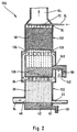
- FIG. 2 the residual heat exchanger and the exhaust gas purification reactor into one Exhaust gas purification heat exchange unit 128 summarized.
- This Exhaust gas purification heat exchange unit 128 has a residual heat exchanger 130 and an exhaust gas purification reactor 132, which is related to the direction of gravity above the Residual heat exchanger 130 is arranged.
- the emission control reactor 132 and the residual heat exchanger 130 are fundamental constructed as above for the residual heat exchanger 38 and described the exhaust gas purification reactor 48, the residual heat exchanger 130 and the exhaust gas purification reactor 132 together are connected.
- the exhaust gas purification reactor 132 has a lower one A flow-through element 134 at the end of the exhaust gas cleaning chamber 50 for subcarrier medium with a variety of Openings 136 is provided so that the intermediate carrier medium Distributor 94 of the residual heat exchanger 130 can flow.
- the exhaust gas purification reactor has in its lower area 132 on a collection area 138 for intermediate carrier medium, the corresponds to a condensate sump. Via an outlet 140 can Intermediate carrier medium from the collection area 138 into the line Stream 96.
- the intermediate carrier medium located in the collection area 138 is present at the distributor 94 of the residual heat exchanger 130.
- Of the Outlet 140 is based on the direction of gravity in a predetermined height 142 above the manifold 94.
- the collection area 138 with outlet 140 thus acts as Branch, by means of which a partial flow via outlet 140 into line 96 for promotion in the second circuit 120 can be branched off and by means of the intermediate carrier medium Residual heat exchanger 130 for transportation in the first circuit 58 can be fed.
- the division into a first and an the second partial flow is determined by the vertical height 142 as well as the number and the diameter of Bores in the distributor 94, which in particular as Nozzle plate is formed, determined.
- the device according to the invention works as follows:
- the intermediate carrier medium which via the entry 92 in the Residual heat exchanger 36 enters through the manifold 94 in monodisperse drops dispersed.
- the decay of an intermediate medium beam in the drop occurs after falling through a decay length.
- This drop of drops in one Monodisperse residual heat exchanger is in the not previously published German patent applications with the file number 195 43 452.8-16 and 195 43 449.8-16 from the same applicant described. We hereby expressly acknowledge these registrations Referred.
- the average droplet size is preferably in the decayed state Jet so that no drops from the exhaust gas from the Residual heat exchanger 38 are torn out.
- the exhaust gas comes in Contact with the drops of the monodisperse medium spray, and water from the exhaust gas hits the Drops of the intermediate carrier medium. It becomes palpable and gained latent heat.
- the exhaust gas, which residual heat has released the intermediate carrier medium is used for cleaning fed to the exhaust gas purification reactor 48.
- heating water heat exchanger 30 there is Intermediate medium almost completely absorbs the heat absorbed to the heating water in the heating water return 22.
- the absorbed by the intermediate carrier medium in the residual heat exchanger 38 Heat causes an increase in temperature in the range of about 5 K to 20 K.
- the intermediate carrier medium is via the guide section 122 through the exhaust gas purification reactor 48 and the branch 88 in guided and circulates the residual heat exchanger 38 on this Way in the first intermediate carrier medium circuit thereby formed 56.
- the exhaust gas from the furnace 12 contains impurities and Pollutants and due to the sulfur content in the fossil Fuels especially sulfur dioxide and other sulfur compounds. These sulfur compounds are in the Intermediate carrier medium solved and cause acidification of the Intermediate medium.
- Heat exchange chamber 36 becomes part of the sulfur dioxide from the Exhaust gas washed out.
- the essential step of exhaust gas cleaning takes place in the exhaust gas purification reactor 48.
- the mass flows of the intermediate carrier medium are in the first Circuit 56 and in the second circuit 120 adapted so that there is an optimized heat exchange in the residual heat exchanger and optimized exhaust gas purification in the exhaust gas purification reactor 48 results.
- 56 the mass flow via the mass flow control element 66 and in second circuit 120 of the mass flow via the mass control element 116 controlled.
- the mass flow is preferably so chosen that he in the second circuit 120 by 2.8 times to 25 times and in particular about 7 times higher than the mass flow in the first circuit 58.
- the exhaust gas which is the residual heat exchanger 38 has flowed through, the exhaust gas purification reactor 48, and there is the sulfur dioxide still contained in the exhaust gas largely washed out by the intermediate carrier medium. This further acidifies the intermediate carrier medium.
- the intermediate carrier medium is fed to the neutralizer 102 via the line 96 from the branch 88.
- a neutralizing agent in particular an alkali or alkaline earth metal oxide such as MgO or CaO, is arranged in the neutralizer.
- this metal oxide forms a hydroxide-water solution, for example an Mg (OH) 2 water solution in the case of MgO as the neutralizing agent.
- the sulfur dioxide forms metal sulfate ions in this solution, for example MgSO 4 ions, which dissolve in the intermediate carrier medium and circulate with the latter in the intermediate carrier medium circulation through the intermediate carrier medium circulation. After several cycles, the enriched intermediate carrier medium is removed.
- this goes through Intermediate carrier medium downstream of the neutralizer 102 Air injector 106.
- This is used for the oxidation of in the sulfite ions dissolved in the intermediate carrier medium to become non-toxic Air sulfates ions.
- this is only necessary when the combustion air ratio in burner 14 is close is at the stoichiometric value; the exhaust gas contains Air numbers still at a distance from the stoichiometric value enough oxygen to oxidize sulfite in sulfate.
- the intermediate carrier medium circulates via the junction 72 via the guide section 122 in the second intermediate medium circuit 120.
- the neutralizer is on a higher gravitational potential 126 compared to the overflow 44 arranged.
- the intermediate medium circulation stops can thereby intermediate medium from the Drain neutralizer 102 over the overflow 44 so that the Neutralizer 102 falls dry and no intermediate carrier medium at the neutralizing agent. This ensures that the pH of the intermediate carrier medium in the Intermediate medium circulation 56 in every operating state not shifted to a basic area, but in one is slightly acidic or neutral. This prevents Deposits causing malfunctions.
- the overflow 44 is enriched with metal sulfate Intermediate carrier medium discharged.
- the metal sulfate concentration is essentially the same as for the intermediate carrier medium in the subcarrier medium circulation, since this during circulation is well mixed and stirred.
- Magnesium sulfate (“Epsom salt”) formed during neutralization can be used primarily as a fertilizer for conifers. It can also be provided according to the invention that the removed intermediate carrier medium is fed to a sulfate separator in which 2 insoluble calcium sulfate (gypsum) is formed by adding, for example, CaO, lime milk or Ca (OH). This means that no or significantly less sulfate gets into the sewage system.
- gypsum 2 insoluble calcium sulfate
- the intermediate carrier medium flows in particular intensified then when the subcarrier medium circulation stops, as a medium from higher areas runs into the condensate sump 42 and its mirror over the overflow 44 lifts.
- the method provides that when the Burner 14, the shut-off valve 98 is closed, so that in the second circuit 120 no longer an intermediate carrier medium circulates. In this way, the intermediate carrier medium from decoupled from the neutralizing agent. But it can still be through the intermediate carrier medium in the first circuit Use the absorbed heat by using the subcarrier heating water heat exchanger 30 still in at least one Circulation circulation can go through.
- control valve 98 a certain period of time is closed before the burner 14 is switched off.
- the method according to the invention runs in the same way as described above when the exhaust gas purification heat exchange unit 128 instead of separate residual heat exchanger and exhaust gas cleaning reactor is used.
- Control valve 98 is a three-way valve
- the resulting over-neutralization of the Intermediate carrier medium is thereby the next time the burner is started compensates for the acidic intermediate carrier medium from the control valve 98 branches and bypassed by line 101 of the neutralizer 102 into the junction 103 to be led.
- the branched portion is over the pH value measured by the pH measuring device 75 Controlled intermediate medium. That way you can over-neutralized intermediate carrier medium from the neutralizer 102 dissipate and consume.
- the device according to the invention provides that the Exhaust gas cleaning and the residual heat exchanger with the exhaust gas in a residual heat exchanger 196 takes place (Fig. 4).
- the first Circuit 122 and the second circuit 120 are in the essentially constructed as described above.
- the line 74 then opens into an entrance of a junction 198 and opens from a first exit of this branch 198 a line 199 into the residual heat exchanger 196.
- the intermediate carrier medium is in this variant in the residual heat exchanger 196 cleaned and absorbs heat. Before inflow in the residual heat exchanger 196 is via the branch 198 part of the intermediate carrier medium in the second circuit 122 branched to neutralize it. Execution a part of the intermediate carrier medium from the first circuit 122 via the branch 202, the line 204 and the Merge 206 into the second circuit 120 Degree of neutralization increased because part of the directly from the Residual heat exchanger coming in acid exhaust gas condensate directly the second circuit 120 with the neutralizer 102 becomes.
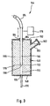
- An embodiment of a neutralizer according to the invention which is designated as a whole by 144 in FIG. 3, includes a container 146 with container bottom 148, container walls 150 and container lid 152.
- an opening 154 is preferably arranged centrally, via which a liquid medium, for example intermediate carrier medium, can be guided into the interior of the container.
- a liquid medium for example intermediate carrier medium
- the Container bottom 148 has an opening 156, by means of which the liquid medium from the tank 146 of the neutralizer is dissipatable.
- a neutralizing agent 158 arranged, which is preferably in granular form is present.
- This can in particular be an alkali or Act alkaline earth oxide such as MgO or CaO that are used for neutralizing an intermediate carrier medium which acidified by washing out sulfur dioxide from an exhaust gas is.
- the container 146 has one near its upper end Refill nozzle 160 with a closable cover 162, is refillable via the neutralizing agent.
- a lower end 168 of the tube 166, which in the Container 146 opens, is from an upper end of the Container bottom 148 to a lower end of the container lid 152 movable.
- the pipe guide is designed so that the lower end 168 when it is at the upper end of the tank bottom 148 is present, directly into the opening 156, through which a discharge line 170 for liquid medium from the neutralizer exits, is present. This allows liquid medium to flow directly be passed through the neutralizer 144 without this comes into contact with the neutralizing agent 158.
- the neutralizing agent 158 preferably so inside the container arranged that a tubular neutralization agent-free Recess 172 for the displacement of the tube 166 is available.
- the tube 166 is flexible at its upper end Feed 174, for example a hose, connected via which the liquid medium is supplied and which ensures that the tube 166 is slidable.
- a stepper motor 176 the axial displacement of the tube 166 controls.
- the neutralizer according to the invention works as follows:
- liquid medium in particular Intermediate carrier medium
- the vertical distance from the lower end 168 of the tube to that Container bottom 148 determines the extent to which neutralizing agent is wetted by the liquid medium.
- the of amount of neutralizing agent that can be taken up in the liquid medium is proportional to the wetted area of neutralizing agent in container 146, wherein to achieve a high surface area it is particularly advantageous if that Neutralizing agent is present as granules.
- the neutralizing agent lies as coarse-grained Granules before, so that in particular it is ensured that a Liquid level 178 of liquid medium in the neutralizer 144 only slightly above a level due to adhesive forces of the lower end 168 of the tube 166 can rise.
- the degree of neutralization can then be determined by the neutralizer control or adjust in the liquid medium. This can for example in a liquid medium circulation at one or several places the pH value is measured and the tube 166 be moved until you find the one you want or receives the required pH. Raising or lowering the Tube 166 can be done with stepper motor 176.
- the neutralizing agent is not in a very pure form, the problem sometimes arises that it can cake if it falls dry.
- MgO granules can bake through CaSO 4 formed.
- the caking may form a framework that hinders the trickling of granules from areas above the liquid level 178 to the area below the liquid level 178 that can be wetted with liquid medium.
Abstract
Description
- Fig. 1
- ein Ausführungsbeispiel einer erfindungsgemäßen Vorrichtung;
- Fig. 2
- ein Ausführungsbeispiel einer Abgasreinigungs-Wärmetausch-Einneit;
- Fig. 3
- ein Ausführungsbeispiel eines erfindungsgemäßen Neutralisators und
- Fig. 4
- ein weiteres Ausführungsbeispiel einer erfindungsgemäßen Vorrichtung.
Claims (71)
- Verfahren zur Reinigung eines Abgases einer Feuerungsanlage, insbesondere einer Ölfeuerungsanlage, bei dem das Abgas in einem Restwärmetauscher Restwärme, welche restliche fühlbare und latente Wärme umfaßt, an ein Zwischenträgermedium abgibt und bei dem das Abgas mittels Zwischenträgermedium gereinigt und insbesondere entschwefelt wird, wobei das Zwischenträgermedium in einem Zwischenträgermedium-Umlauf geführt wird und mittels eines Neutralisationsmittels neutralisiert wird, dadurch gekennzeichnet, daß das Zwischenträgermedium vom Neutralisationsmittel abgekoppelt wird, wenn Überneutralisierung des Zwischenträgermediums eintreten kann.
- Verfahren nach Anspruch 1, dadurch gekennzeichnet, daß das Zwischenträgermedium vom Neutralisationsmittel bei Stillstand eines Brenners der Feuerungsanlage abgekoppelt wird.
- Verfahren nach Anspruch 1 oder 2, dadurch gekennzeichnet, daß das Zwischenträgermedium bei Anhalten einer Zwischenträgermedium-Zirkulation im Zwischenträgermedium-Umlauf vom Neutralisationsmittel abgekoppelt wird.
- Verfahren nach einem der vorangehenden Ansprüche, dadurch gekennzeichnet, daß das Zwischenträgermedium auf einen pH-Wert im Bereich von 5,5 bis 7, insbesondere auf ca. 6,5, neutralisiert wird.
- Verfahren nach einem der vorangehenden Ansprüche, dadurch gekennzeichnet, daß als Neutralisationsmittel ein Metalloxid und insbesondere ein Alkali- oder Erdalkalioxid verwendet wird.
- Verfahren nach Anspruch 5, dadurch gekennzeichnet, daß als Neutralisationsmittel MgO verwendet wird.
- Verfahren nach einem der vorangehenden Ansprüche, dadurch gekennzeichnet, daß das Neutralisationsmittel in einem Neutralisator angeordnet ist, welcher von dem Zwischenträgermedium durchströmbar ist.
- Verfahren nach Anspruch 7, dadurch gekennzeichnet, daß die Abkopplung des Zwischenträgermediums vom Neutralisationsmittel durch ein Trockenfallen des Neutralisationsmittels in dem Neutralisator bewirkt wird.
- Verfahren nach Anspruch 8, dadurch gekennzeichnet, daß der Neutralisator bezogen auf die Schwerkraftrichtung oberhalb einer Abführung für Zwischenträgermedium aus einem Kondensatsumpf des Restwärmetauschers angeordnet ist, so daß durch die Schwerkraft ein Trockenfallen des Neutralisators bewirkbar ist.
- Verfahren nach einem der vorangehenden Ansprüche, dadurch gekennzeichnet, daß das Neutralisationsmittel als Granulat vorliegt.
- Verfahren nach Anspruch 10, dadurch gekennzeichnet, daß das Maß der durch das Zwischenträgermedium benetzten Neutralisationsmittel-Oberfläche einstellbar ist.
- Verfahren nach einem der vorangehenden Ansprüche, dadurch gekennzeichnet, daß der pH-Wert des Zwischenträgermediums an mindestens einer Stelle im Zwischenträgermedium-Umlauf gemessen wird.
- Verfahren nach Anspruch 12, dadurch gekennzeichnet, daß die durch das Zwischenträgermedium benetzte Neutralisationsmitteloberfläche so eingestellt wird, daß sich der vorgegebene pH-Wert im Zwischenträgermedium einstellt.
- Verfahren nach einem der vorangehenden Ansprüche, dadurch gekennzeichnet, daß das Zwischenträgermedium ein Abgaskondensat ist.
- Verfahren nach Anspruch 14, dadurch gekennzeichnet, daß das aus dem Abgas abgeschiedene Kondensat mehrmals im Zwischenträgermedium-Umlauf als Zwischenträgermedium geführt wird, bevor es aus dem Zwischenträgermedium-Umlauf abgeführt wird.
- Verfahren nach Anspruch 15, dadurch gekennzeichnet, daß das abgeführte Zwischenträgermedium mit Wasser verdünnt wird.
- Verfahren nach einem der vorangehenden Ansprüche, dadurch gekennzeichnet, daß ein Restwärmetausch des Abgases mit dem Zwischenträgermedium und die Abgasreinigung durch das Zwischenträgermedium im wesentlichen in getrennten Stufen erfolgt.
- Verfahren nach Anspruch 17, dadurch gekennzeichnet, daß zur Abgasreinigung ein Abgasreinigungsreaktor vorgesehen ist.
- Verfahren nach Anspruch 17 oder 18, dadurch gekennzeichnet, daß bezogen auf den Abgasstrom die Abgasreinigung der Wärmetauschstufe nachgeschaltet ist.
- Verfahren nach Anspruch 18 oder 19, dadurch gekennzeichnet, daß der Abgasreinigungsreaktor bezogen auf die Schwerkraftrichtung oberhalb des Restwärmetauschers angeordnet ist.
- Verfahren nach Anspruch 19 oder 20, dadurch gekennzeichnet, daß der Zwischenträgermedium-Umlauf einen ersten Zwischenträgermedium-Kreislauf, in dem das Zwischenträgermedium Wärme aus dem Abgas aufnimmt, und einen zweiten Zwischenträgermedium-Kreislauf, in dem das Zwischenträgermedium zur Reinigung des Abgases dient, umfaßt.
- Verfahren nach Anspruch 21, dadurch gekennzeichnet, daß das Zwischenträgermedium in einer Führungsstrecke des Zwischenträgermedium-Umlaufs geführt wird, welche dem ersten und dem zweiten Zwischenträgermedium-Kreislauf gemeinsam ist.
- Verfahren nach Anspruch 21 oder 22, dadurch gekennzeichnet, daß das Zwischenträgermedium mittels eines Zwischenträgermedium-Heizwasser-Wärmetauschers, welcher im ersten Zwischenträgermedium-Kreislauf angeordnet ist, Wärme an Heizwasser in einem Heizkreis abgibt.
- Verfahren nach einem der Ansprüche 20 bis 23, dadurch gekennzeichnet, daß der Massestrom des Zwischenträgermediums im zweiten Zwischenträgermedium-Kreislauf beim 2,8-fachen bis 25-fachen und insbesondere beim ca. 7-fachen des Massestroms im ersten Zwischenträgermedium-Kreislauf liegt.
- Verfahren nach einem der Ansprüche 21 bis 24, dadurch gekennzeichnet, daß die gemeinsame Führungsstrecke für das Zwischenträgermedium einen Abgasreinigungsraum des Abgasreinigungsreaktors umfaßt.
- Verfahren nach Anspruch 25, dadurch gekennzeichnet, daß Zwischenträgermedium von dem Abgasreinigungsreaktor dem Restwärmetauscher zugeführt wird.
- Verfahren nach Anspruch 26, dadurch gekennzeichnet, daß Zwischenträgermedium von der Zuführung vom Abgasreinigungsreaktor zum Restwärmetauscher zur Bildung des zweiten Zwischenträgermedium-Kreislaufs abgezweigt wird.
- Verfahren nach einem der Ansprüche 20 bis 27, dadurch gekennzeichnet, daß Zwischenträgermedium im zweiten Zwischenträgermedium-Kreislauf durch einen Neutralisator geführt wird, in welchem das Neutralisationsmittel angeordnet ist.
- Verfahren nach Anspruch 28, dadurch gekennzeichnet, daß ein Brennerstillstand ein Anhalten der Zirkulation des Zwischenträgermediums im zweiten Zwischenträgermedium-Kreislauf bewirkt.
- Verfahren nach Anspruch 29, dadurch gekennzeichnet, daß bei Stillstand des Brenners das Zwischenträgermedium im ersten Zwischenträgermedium-Kreislauf zur Abgabe der aufgenommenen Wärme noch mindestens einen Umlauf durchführt.
- Verfahren nach Anspruch 29 oder 30, dadurch gekennzeichnet, daß das Anhalten der Zirkulation des Zwischenträgermediums im zweiten Zwischenträgermedium-Kreislauf in einer bestimmten Zeitspanne vor dem Brennerstillstand erfolgt.
- Verfahren nach Anspruch 31, dadurch gekennzeichnet, daß ein Brennschlußsignal der Feuerungsanlage vor dem Bewirken eines Brennerstillstands ein Anhalten der Zirkulation des Zwischenträgermediums im zweiten Zwischenträgermedium-Kreislauf bewirkt.
- Verfahren nach einem der Ansprüche 29 bis 32, dadurch gekennzeichnet, daß das Anhalten der Zirkulation von Zwischenträgermedium im zweiten Zwischenträgermedium-Kreislauf durch das Schließen eines Steuerventils bewirkt wird.
- Vorrichtung zur Reinigung und insbesondere Entschwefelung eines Abgases einer Feuerungsanlage und insbesondere einer Ölfeuerungsanlage, welche einen Restwärmetauscher umfaßt, in dem durch das Abgas Restwärme, welche restliche fühlbare und latente Wärme umfaßt, an ein Zwischenträgermedium abgebbar ist, wobei das Abgas mittels des Zwischenträgermediums reinigbar ist und wobei das Zwischenträgermedium in einem Zwischenträgermedium-Umlauf geführt ist, und welche einen Neutralisator mit einem Neutralisationsmittel zur Neutralisierung des Zwischenträgermediums umfaßt, dadurch gekennzeichnet, daß die Vorrichtung ein Mittel (126; 166) zum Abkoppeln des Zwischenträgermediums vom Neutralisationsmittel (158) umfaßt, um eine Überneutralisierung des Zwischenträgermediums zu verhindern.
- Vorrichtung nach Anspruch 34, dadurch gekennzeichnet, daß bei Stillstand eines Brenners (14) der Feuerungsanlage (12) das Zwischenträgermedium vom Neutralisationsmittel (158) abkoppelbar ist.
- Vorrichtung nach Anspruch 34 oder 35, dadurch gekennzeichnet, daß bei Anhalten einer Zirkulation des Zwischenträgermediums im Zwischenträgermedium-Umlauf (56) das Zwischenträgermedium vom Neutralisationsmittel (158) abkoppelbar ist.
- Vorrichtung nach einem der Ansprüche 34 bis 36, dadurch gekennzeichnet, daß das Zwischenträgermedium durch das Neutralisationsmittel (158) auf einen pH-Wert von 5,5 bis 7 und insbesondere ca. 6,5 neutralisierbar ist.
- Vorrichtung nach Anspruch 37, dadurch gekennzeichnet, daß das Neutralisationsmittel (158) ein Metalloxid und insbesondere ein Alkali- oder Erdalkalioxid ist.
- Vorrichtung nach Anspruch 38, dadurch gekennzeichnet, daß das Neutralisationsmittel MgO ist.
- Vorrichtung nach einem der Ansprüche 34 bis 39, dadurch gekennzeichnet, daß das Neutralisationsmittel (158) in Granulatform vorliegt.
- Vorrichtung nach einem der Ansprüche 34 bis 40, dadurch gekennzeichnet, daß der Neutralisator (102; 144) mit dem Neutralisationsmittel (158) bezogen auf die Schwerkraftrichtung oberhalb (126) einer Abführung (44) eines Kondensatsumpfes (42) des Restwärmetauschers (38) angeordnet ist, so daß aus dem Neutralisator (102; 144) Zwischenträgermedium insbesondere bei Stillstand des Zwischenträgermedium-Umlaufs (56) ablaufen kann.
- Vorrichtung nach einem der Ansprüche 34 bis 41, dadurch gekennzeichnet, daß die Vorrichtung zur Abgasreinigung und insbesondere Abgasentschwefelung einen Abgasreinigungsreaktor (48) umfaßt.
- Vorrichtung nach Anspruch 42, dadurch gekennzeichnet, daß der Abgasreinigungsreaktor (48) bezogen auf den Abgasstrom nach dem Restwärmetauscher (38) angeordnet ist.
- Vorrichtung nach Anspruch 42 oder 43, dadurch gekennzeichnet, daß der Abgasreinigungsreaktor (48; 132) bezogen auf die Schwerkraftrichtung oberhalb des Restwärmetauschers (38; 130) angeordnet ist.
- Vorrichtung nach Anspruch 44, dadurch gekennzeichnet, daß der Abgasreinigungsreaktor (132) und der Restwärmetauscher eine Abgasreinigungs-Wärmetausch-Einheit (128) bilden.
- Vorrichtung nach einem der Ansprüche 42 bis 45, dadurch gekennzeichnet, daß der Zwischenträgermedium-Umlauf (56) einen ersten Zwischenträgermedium-Kreislauf (58), in dem durch das Abgas Wärme an das Zwischenträgermedium abgebbar ist, und einen zweiten Zwischenträgermedium-Kreislauf (120), in dem das Abgas in dem Abgasreinigungsreaktor (48) durch das Zwischenträgermedium reinigbar ist, umfaßt.
- Vorrichtung nach Anspruch 46, dadurch gekennzeichnet, daß der Zwischenträgermedium-Umlauf (56) eine Führungsstrecke (122) aufweist, die dem ersten (58) und dem zweiten (120) Zwischenträgermedium-Kreislauf gemeinsam ist.
- Vorrichtung nach Anspruch 46 oder 47, dadurch gekennzeichnet, daß der zweite Zwischenträgermedium-Kreislauf ein Steuerventil (98) aufweist, mit welchem die Zirkulation des Zwischenträgermediums im zweiten Zwischenträgermedium-Kreislauf (120) sperrbar ist.
- Vorrichtung nach Anspruch 48, dadurch gekennzeichnet, daß die Vorrichtung eine Steuerungs- und Regelungseinheit (99) aufweist, welche den Brenner (14) der Feuerungsanlage (12) steuert und über welchen das Steuerventil (98) im zweiten Zwischenträgermedium-Kreislauf (120) steuerbar ist.
- Vorrichtung nach einem der Ansprüche 46 bis 49, dadurch gekennzeichnet, daß der Neutralisator (102; 144) im zweiten Zwischenträgermedium-Kreislauf (120) angeordnet ist.
- Vorrichtung nach einem der Ansprüche 46 bis 50, dadurch gekennzeichnet, daß der Massestrom an Zwischenträgermedium mittels einem oder mehreren Massestrom-Steuerorganen (66; 116) im zweiten Kreislauf (120) so steuerbar ist, daß er das 2,8-fache bis 25-fache und insbesondere ca. Siebenfache des Massestroms an Zwischenträgermedium im ersten Kreislauf (58) beträgt.
- Vorrichtung nach einem der Ansprüche 34 bis 51, dadurch gekennzeichnet, daß das Zwischenträgermedium aus einem Abgaskondensat gebildet ist.
- Vorrichtung nach einem der Ansprüche 34 bis 52, dadurch gekennzeichnet, daß der Neutralisator (102; 144) so ausgebildet ist, daß eine Menge des im Neutralisator (102; 144) mit Zwischenträgermedium beaufschlagten Neutralisationsmittels (158) einstellbar ist.
- Vorrichtung nach Anspruch 53, dadurch gekennzeichnet, daß das Maß der mit Zwischenträgermedium benetzbaren Neutralisationsmittel-Oberfläche einstellbar ist.
- Vorrichtung nach Anspruch 54, dadurch gekennzeichnet, daß der Neutralisator einen Behälter (146) umfaßt, der von Zwischenträgermedium durchströmbar ist und in dem das Neutralisationsmittel (158) angeordnet ist.
- Vorrichtung nach Anspruch 55, dadurch gekennzeichnet, daß der Neutralisator (144) eine Zuführung (166) aufweist, mittels der Zwischenträgermedium in den Behälter (146) mit Neutralisationsmittel (158) führbar ist, welche in der Höhe bezüglich eines im Behälter angeordneten Vorrats an Neutralisationsmittel (158) verschieblich ist.
- Vorrichtung nach Anspruch 56, dadurch gekennzeichnet, daß die Zuführung (166) zwischen einem bezogen auf die Schwerkraftrichtung unteren Ende des Vorrats an Neutralisationsmittel (158) und einem oberen Ende des Behälters (146) verschieblich ist.
- Vorrichtung nach Anspruch 56 oder 57, dadurch gekennzeichnet, daß die Zuführung (166) an einem bezogen auf die Schwerkraftrichtung oberen Ende in den Behälter (146) mit Neutralisationsmittel (158) des Neutralisators (144) geführt ist.
- Vorrichtung nach einem der Ansprüche 56 bis 58, dadurch gekennzeichnet, daß der Behälter (146) mit Neutralisationsmittel (158) an seinem bezogen auf die Schwerkraftrichtung unteren Ende eine Abführung (170) für Zwischenträgermedium aufweist.
- Vorrichtung nach einem der Ansprüche 56 bis 59, dadurch gekennzeichnet, daß der Behälter mit Neutralisationsmittel eine an einem oberen oder in der Nähe seines oberen Endes angeordnete Nachfüllvorrichtung (160) für Neutralisationsmittel (158) aufweist.
- Vorrichtung nach einem der Ansprüche 34 bis 60, dadurch gekennzeichnet, daß der Restwärmetauscher (38; 130) ein Monodispers-Restwärmetauscher ist.
- Neutralisator zur Neutralisierung eines flüssigen Mediums, insbesondere zur Neutralisierung eines Abgaskondensats in einer Heizungsanlage, bei welcher die Restwärme, welche restliche fühlbare und latente Wärme umfaßt, eines Abgases einer Feuerungsanlage der Heizungsanlage genutzt wird, welcher einen Behälter umfaßt, in dem ein Neutralisationsmittel angeordnet ist, und welcher von dem flüssigen Medium durchströmbar ist, dadurch gekennzeichnet, daß das Maß der Beaufschlagung des flüssigen Mediums mit Neutralisationsmittel (158) im Neutralisator (144) mittels einer Flüssigmedium-Zuführungsvorrichtung (166, 174) einstellbar ist.
- Neutralisator nach Anspruch 62, dadurch gekennzeichnet, daß durch die Flüssigmedium-Zuführungsvorrichtung (166, 174) ein Flüssigkeitsspiegel (178) an flüssigem Medium in dem Behälter (146), in welchem das Neutralisationsmittel (158) angeordnet ist, einstellbar ist.
- Neutralisator nach Anspruch 63, dadurch gekennzeichnet, daß die Flüssigmedium-Zuführungsvorrichtung eine Zuführung (166) umfaßt, welche bezüglich der Anordnung des Neutralisationsmittels (158) im Neutralisator (144) in der Höhe verschieblich ist.
- Neutralisator nach Anspruch 64, dadurch gekennzeichnet, daß die Zuführung (166) bezogen auf die Schwerkraftrichtung an einem oberen Ende des Behälter (146) mit Neutralisationsmittel (158) in diesen geführt ist.
- Neutralisator nach Anspruch 64 oder 65, dadurch gekennzeichnet, daß die Zuführung (166) in einem Bereich, welcher bezogen auf die Schwerkraftrichtung ein unteres Ende eines Vorrats an Neutralisationsmittel in dem Behälter (146) und ein oberes Ende des Behälters (146) umfaßt, verschieblich ist.
- Neutralisator nach einem der Ansprüche 64 bis 66, dadurch gekennzeichnet, daß die Zuführung durch ein Rohr (166) gebildet ist, das in dem Behälter (146) verschieblich ist.
- Neutralisator nach einem der Ansprüche 62 bis 67, dadurch gekennzeichnet, daß der Behälter (146) mit Neutralisationsmittel (158) an seinem unteren Ende eine Abführung (170) für das flüssige Medium aufweist.
- Neutralisator nach einem der Ansprüche 62 bis 68, dadurch gekennzeichnet, daß der Behälter (146) an oder in der Nähe seines oberen Endes eine Nachfüllvorrichtung (160) für Neutralisationsmittel (158) aufweist.
- Neutralisator nach einem der Ansprüche 62 bis 69, dadurch gekennzeichnet, daß das Neutralisationsmittel (158) als Granulat vorliegt.
- Neutralisator nach einem der Ansprüche 68 bis 70, dadurch gekennzeichnet, daß ein Durchmesser des Behälters (146) mit Neutralisationsmittel (158) und ein Durchmesser der Abführung (170) für flüssiges Medium so angepaßt sind, daß flüssiges Medium ohne Rückstau durch den Neutralisator (144) strömbar ist.
Applications Claiming Priority (2)
| Application Number | Priority Date | Filing Date | Title |
|---|---|---|---|
| DE1997109803 DE19709803A1 (de) | 1997-03-10 | 1997-03-10 | Verfahren zur Reinigung eines Abgases einer Feuerungsanlage |
| DE19709803 | 1997-03-10 |
Publications (2)
| Publication Number | Publication Date |
|---|---|
| EP0864352A2 true EP0864352A2 (de) | 1998-09-16 |
| EP0864352A3 EP0864352A3 (de) | 1999-01-07 |
Family
ID=7822853
Family Applications (1)
| Application Number | Title | Priority Date | Filing Date |
|---|---|---|---|
| EP98103856A Withdrawn EP0864352A3 (de) | 1997-03-10 | 1998-03-05 | Verfahren zur Reinigung eines Abgases einer Feuerungsanlage |
Country Status (2)
| Country | Link |
|---|---|
| EP (1) | EP0864352A3 (de) |
| DE (1) | DE19709803A1 (de) |
Cited By (1)
| Publication number | Priority date | Publication date | Assignee | Title |
|---|---|---|---|---|
| WO2009093073A2 (en) * | 2008-01-25 | 2009-07-30 | Enertek International Limited | Heat exchanger apparatus, system and method |
Families Citing this family (1)
| Publication number | Priority date | Publication date | Assignee | Title |
|---|---|---|---|---|
| CN108786407B (zh) * | 2018-07-20 | 2020-07-14 | 江苏峰峰鸿运环保科技发展有限公司 | 一种环保用工业烟气净化处理设备 |
Citations (7)
| Publication number | Priority date | Publication date | Assignee | Title |
|---|---|---|---|---|
| EP0097631A2 (de) * | 1982-06-17 | 1984-01-04 | Ulf Johansson | Verfahren und Vorrichtung zum Verbrennen von fliessfähigem Brennstoff |
| EP0138781A2 (de) * | 1983-08-31 | 1985-04-24 | Erik Lindahl | Methode und Apparat zur Rauchgasreinigung |
| EP0151398A1 (de) * | 1984-01-18 | 1985-08-14 | DEUTSCHE FORSCHUNGSANSTALT FÜR LUFT- UND RAUMFAHRT e.V. | Verfahren und Vorrichtung zur Rauchgasentschwefelung bei Heizölfeuerungen |
| EP0243778A2 (de) * | 1986-04-28 | 1987-11-04 | Horst Qualmann | Verfahren und Vorrichtung zum Reinigen von Abgasen |
| DE3716610A1 (de) * | 1987-05-18 | 1989-02-02 | Gebhard Noeth | Verfahren zum entfernen von schadstoffen aus rauchgasen, sowie vorrichtung zur durchfuehrung des verfahrens |
| EP0454948A2 (de) * | 1990-03-30 | 1991-11-06 | Aquamot Ag | Verfahren und Vorrichtung zur Beseitigung der Säure- und Schwermetallverunreinigungen aus Flüssigkeiten |
| EP0775873A1 (de) * | 1995-11-22 | 1997-05-28 | DEUTSCHE FORSCHUNGSANSTALT FÜR LUFT- UND RAUMFAHRT e.V. | Verfahren und Vorrichtung zur Nutzung der restlichen fühlbaren und der latenten Wärme eines Abgases einer Feuerungsanlage |
-
1997
- 1997-03-10 DE DE1997109803 patent/DE19709803A1/de not_active Ceased
-
1998
- 1998-03-05 EP EP98103856A patent/EP0864352A3/de not_active Withdrawn
Patent Citations (7)
| Publication number | Priority date | Publication date | Assignee | Title |
|---|---|---|---|---|
| EP0097631A2 (de) * | 1982-06-17 | 1984-01-04 | Ulf Johansson | Verfahren und Vorrichtung zum Verbrennen von fliessfähigem Brennstoff |
| EP0138781A2 (de) * | 1983-08-31 | 1985-04-24 | Erik Lindahl | Methode und Apparat zur Rauchgasreinigung |
| EP0151398A1 (de) * | 1984-01-18 | 1985-08-14 | DEUTSCHE FORSCHUNGSANSTALT FÜR LUFT- UND RAUMFAHRT e.V. | Verfahren und Vorrichtung zur Rauchgasentschwefelung bei Heizölfeuerungen |
| EP0243778A2 (de) * | 1986-04-28 | 1987-11-04 | Horst Qualmann | Verfahren und Vorrichtung zum Reinigen von Abgasen |
| DE3716610A1 (de) * | 1987-05-18 | 1989-02-02 | Gebhard Noeth | Verfahren zum entfernen von schadstoffen aus rauchgasen, sowie vorrichtung zur durchfuehrung des verfahrens |
| EP0454948A2 (de) * | 1990-03-30 | 1991-11-06 | Aquamot Ag | Verfahren und Vorrichtung zur Beseitigung der Säure- und Schwermetallverunreinigungen aus Flüssigkeiten |
| EP0775873A1 (de) * | 1995-11-22 | 1997-05-28 | DEUTSCHE FORSCHUNGSANSTALT FÜR LUFT- UND RAUMFAHRT e.V. | Verfahren und Vorrichtung zur Nutzung der restlichen fühlbaren und der latenten Wärme eines Abgases einer Feuerungsanlage |
Cited By (2)
| Publication number | Priority date | Publication date | Assignee | Title |
|---|---|---|---|---|
| WO2009093073A2 (en) * | 2008-01-25 | 2009-07-30 | Enertek International Limited | Heat exchanger apparatus, system and method |
| WO2009093073A3 (en) * | 2008-01-25 | 2013-06-27 | Enertek International Limited | Heat exchanger apparatus, system and method |
Also Published As
| Publication number | Publication date |
|---|---|
| EP0864352A3 (de) | 1999-01-07 |
| DE19709803A1 (de) | 1998-09-17 |
Similar Documents
| Publication | Publication Date | Title |
|---|---|---|
| DE3614385C2 (de) | ||
| DE69816509T2 (de) | Verfahren zur Abgasbehandlung | |
| DE2849607C2 (de) | ||
| EP1108187B1 (de) | Verfahren und vorrichtung zur verringerung der schadstoffemission von heizungskleinanlagen | |
| CH637603A5 (de) | Anlage zur biologischen reinigung von wasser. | |
| DE3429956C2 (de) | ||
| EP0172375A1 (de) | Vorrichtung zur Erhitzung eines Fluidums und zur Reinigung der Abgase von Feurerungsanlagen | |
| EP1970116B1 (de) | Anlage und Verfahren zur Rauchgasreinigung | |
| EP3124096B1 (de) | Kalkstein/kalkhydrat-rauchgasreinigungsanlage mit reingas-bypasskanal und sumpferweiterungssystem | |
| DE3831385C2 (de) | Verfahren und Vorrichtung zum Betreiben eines Rohrbündel-Apparates | |
| EP0810407B1 (de) | Verfahren und Vorrichtung zur Nutzung der die restliche fühlbare und die latente Wärme umfassenden Restwärme eines Abgases einer Feuerungsanlage | |
| EP0151398B1 (de) | Verfahren und Vorrichtung zur Rauchgasentschwefelung bei Heizölfeuerungen | |
| EP0864352A2 (de) | Verfahren zur Reinigung eines Abgases einer Feuerungsanlage | |
| DE3716610A1 (de) | Verfahren zum entfernen von schadstoffen aus rauchgasen, sowie vorrichtung zur durchfuehrung des verfahrens | |
| DE3509782C2 (de) | ||
| EP0089036A1 (de) | Verfahren zum Reinigen von Abgasen und zur Rückgewinnung von Wärme und Vorrichtung zur Durchführung des Verfahrens | |
| EP0864816B1 (de) | Verfahren und Vorrichtung zur Nutzung der Restwärme eines Abgases einer Feuerungsanlage | |
| DE3611655C2 (de) | ||
| EP0094652A2 (de) | Heizeinrichtung mit Abgas-Wärmepumpe | |
| DE2109324C3 (de) | Abgasreinigungsvorrichtung | |
| DE19717883C2 (de) | Reinigungsgerät für eine Flüssigkeit, insbesondere in geschlossenen Kreisläufen und Verfahren zum Reinigen einer Flüssigkeit | |
| CH636774A5 (en) | Process for purifying the waste gases from industrial furnaces, in particular from waste incinerators | |
| EP0233971A1 (de) | Verfahren zur Rauchgasabreinigung aus Ölbefeuerten Hausheizungsanlagen | |
| CH635755A5 (en) | Process and equipment for scrubbing flue gases | |
| DE3331768A1 (de) | Vorrichtung zur behandlung von von heizungsanlagen abgegebenen abgasen |
Legal Events
| Date | Code | Title | Description |
|---|---|---|---|
| PUAI | Public reference made under article 153(3) epc to a published international application that has entered the european phase |
Free format text: ORIGINAL CODE: 0009012 |
|
| AK | Designated contracting states |
Kind code of ref document: A2 Designated state(s): AT BE CH DE DK ES FI FR GB GR IE IT LI LU MC NL PT SE |
|
| AX | Request for extension of the european patent |
Free format text: AL;LT;LV;MK;RO;SI |
|
| PUAL | Search report despatched |
Free format text: ORIGINAL CODE: 0009013 |
|
| AK | Designated contracting states |
Kind code of ref document: A3 Designated state(s): AT BE CH DE DK ES FI FR GB GR IE IT LI LU MC NL PT SE |
|
| AX | Request for extension of the european patent |
Free format text: AL;LT;LV;MK;RO;SI |
|
| AKX | Designation fees paid | ||
| STAA | Information on the status of an ep patent application or granted ep patent |
Free format text: STATUS: THE APPLICATION IS DEEMED TO BE WITHDRAWN |
|
| 18D | Application deemed to be withdrawn |
Effective date: 19990708 |
|
| REG | Reference to a national code |
Ref country code: DE Ref legal event code: 8566 |