EP0097631A2 - Verfahren und Vorrichtung zum Verbrennen von fliessfähigem Brennstoff - Google Patents
Verfahren und Vorrichtung zum Verbrennen von fliessfähigem Brennstoff Download PDFInfo
- Publication number
- EP0097631A2 EP0097631A2 EP83850160A EP83850160A EP0097631A2 EP 0097631 A2 EP0097631 A2 EP 0097631A2 EP 83850160 A EP83850160 A EP 83850160A EP 83850160 A EP83850160 A EP 83850160A EP 0097631 A2 EP0097631 A2 EP 0097631A2
- Authority
- EP
- European Patent Office
- Prior art keywords
- fluid
- chamber
- gases
- bodies
- column
- Prior art date
- Legal status (The legal status is an assumption and is not a legal conclusion. Google has not performed a legal analysis and makes no representation as to the accuracy of the status listed.)
- Withdrawn
Links
Images
Classifications
-
- F—MECHANICAL ENGINEERING; LIGHTING; HEATING; WEAPONS; BLASTING
- F28—HEAT EXCHANGE IN GENERAL
- F28D—HEAT-EXCHANGE APPARATUS, NOT PROVIDED FOR IN ANOTHER SUBCLASS, IN WHICH THE HEAT-EXCHANGE MEDIA DO NOT COME INTO DIRECT CONTACT
- F28D21/00—Heat-exchange apparatus not covered by any of the groups F28D1/00 - F28D20/00
- F28D21/0001—Recuperative heat exchangers
- F28D21/0003—Recuperative heat exchangers the heat being recuperated from exhaust gases
- F28D21/0005—Recuperative heat exchangers the heat being recuperated from exhaust gases for domestic or space-heating systems
- F28D21/0007—Water heaters
-
- B—PERFORMING OPERATIONS; TRANSPORTING
- B01—PHYSICAL OR CHEMICAL PROCESSES OR APPARATUS IN GENERAL
- B01D—SEPARATION
- B01D53/00—Separation of gases or vapours; Recovering vapours of volatile solvents from gases; Chemical or biological purification of waste gases, e.g. engine exhaust gases, smoke, fumes, flue gases, aerosols
- B01D53/34—Chemical or biological purification of waste gases
-
- F—MECHANICAL ENGINEERING; LIGHTING; HEATING; WEAPONS; BLASTING
- F23—COMBUSTION APPARATUS; COMBUSTION PROCESSES
- F23J—REMOVAL OR TREATMENT OF COMBUSTION PRODUCTS OR COMBUSTION RESIDUES; FLUES
- F23J15/00—Arrangements of devices for treating smoke or fumes
Definitions
- the combustion gases from a furnace where fluid fuel is burnt should have a certain temperature in order to prevent condensation upon the heat exchanging surfaces. This means a considerable heat-loss, and the gases will contain sulphur compounds, which may damage the flue structure and also means a general environmental troubled
- the starting of a burner in a cold combustion chamber, as well as a erroneous adjustment of the burner, will cause the generation of soot.
- the aim of the present invention is to propose a device, which is especially suited for the burning of oil in furnaces of a size common in domestic boilers, and which makes it possible to neutralize acid constituents in the gases, as well as efficiently to recover residual heat.
- a method according to the invention is characterized in passing the combustion gases through a chamber containing bodies of refractory material offering a large contact surface to the gases.
- the gases are, downstream of the chamber, passed through a second chamber, in which a neutralizing agent containing fluid is sprayed, collected and recirculated, after heat absorbed by the fluid having been recovered.
- a device is characterized in a chamber located adjacent to a burner and arranged to be passed through by the combustion gases and where the gases are brought into contact with bodies of refractory material offering a large contact surface to the gases.
- the chamber is preferably formed as a hopper containing a plurality of individual bodies.
- the chamber may include a cylindrical tube of refractory material,the bodies being located adjacent to the gas exit therefrom.
- the tube is preferably divided longitudinally, in at least two parts.
- the bodies may be formed into a slab, insertable in the tube exit end.
- a second chamber is advantageously located downstream of the first mentioned chamber and is provided with means for spraying a neutralizing agent containing fluid in the path of the combustion gases, and forming part of a column in the lower portion of which the fluid is collected for recirculation and recovery of heat absorbed by the fluid.
- the second chamber may contain a plurality of individual bodies to be sprayed by the fluid.
- a conduit is provided, which from the lower portion of the column extends vertically upwards, and, at a highest permissible fluid level in the fluid collecting portion of the column is terminated by a 360° loop having a downwardly directed discharge.
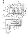
- the combustion device shown in Figure 1 includes a combustion part 10 and a column shaped part 11.
- the combustion part comprises two portions arranged perpendicularly to each other and is enclosed in a water casing 12.
- An oil burner 13 is mounted horizontally in the upper combustion portion and a combustion space 14 extends above the vertical portion 15 of the combustion part.
- the vertical portion is subdivided by vertical and horizontal partitions 16, 17 so as to form an extended passage-way for the gases.
- the vertical portion 15 forms a hopper, which is filled with bodies 18 of refractory material, which are adapted to offer large contact surface within a restricted space.
- the combustion gas exit 19 connecting the combustion part 10 with the column 11 issues from the lower portion of the combustion part. Possible soot particles formed during starting of the burner, or during occasional disturbances of the operation thereof, are caught by the bodies 18 within the hopper 15. These bodies will be incandescent after a short time of operation of the burner. The gases flowing into the column 11 are thus practically free from soot. Within the column acid residues in the gases are neutralized, and residual heat is recovered.
- the combustion gases will flow into the column 11, through conduit 19, which is connected to the lower portion of the column and they will leave the latter through a connection 20 at the top thereof.
- the column 11 is provided with a perforated partition 21, which subdivides its lower portion into two chambers 22 and 23.
- the lower chamber 23 is formed as a fluid collecting pan 24, which is defined by an oblique side wall 25.
- the perforated partition 21 is located just above the entrance of the combustion gas conduit 19, and it carries a plurality of bodies 26 of refractory material, which substantially fill the chamber 22, above the partition 21.
- the combustion gases passing through chamber 22 are washed with a continueously circulated fluid, which contains chemical agents adapted to neutralize the acid sulphur constituents in the gases.
- a suitable agent is magnesium oxid (MgO). It is difficult to dissolve this compound in water, but it has a high density, which makes it easy to separate the neutralization fluid from the addition of condensate which has to be accepted.
- a satisfactory dissolving of magnesium oxide will occur in hot water, and the fluid will, in use, be maintained at an elevated temperature.
- a solution containing magnesium oxide is stored in a container 27, and is metered into the pan 24 by suitable means.
- the neutralizing fluid is circulated by way of a conduit 28 and a pump 29 to the upper part of chamber 22, where it is sprayed through nozzles 30 over the bodies 26.
- the combustion gases pass upwards between the bodies, and are brought into intimate contact with the neutralizing fluid, which covers the surfaces of the bodies.
- the fluid passing downwardly through the layer of bodies 26 drips down through the partition 21 and is collected in the pan 24, where the heavy magnesium oxide containing fluid sinks to the bottom.
- Possible addition of condensate will be collected in the upper part of the pan, and may be withdrawn through a conduit 31. This may be provided with a water trap (not shown) or some similar device determining the fluid level.
- a sensor 32 indicates the concentration of MgO in the fluid, or the density thereof and ensures that the necessary quantity of neutralization agent is available. After some time the chemical compound will be consumed, and the fluid will then have to be drained from the pan by way of a conduit 33. Thereafter the pan is filled with fresh neutralizing fluid.
- the combustion gases will contain a certain amount of heat. This residual heat is partly absorbed by the bodies 26 and partly directly by the circulating fluid and is then by the fluid transferred down into the pan 24. Within the latter a coil 34 is fitted for absorbing the heat, which may be used for heating tap water, or for other purposes.
- the coil 34 is located in the neutralized fluid, and will not be subjected to corrosion attacks.
- neutralizing agent may be arranged by means of devices of arbitrary, known type, and may possibly be arranged so the agent is sprayed directly upon the bodies 26.
- a further chamber 35 is arranged on top of chamber 22, and is separated from the latter by a partition 36. This is provided with a pipe stub 37 serving as a weir and being covered by a lid 38.
- the chamber 35 is filled with ceramic bodies 39, similar to those of chamber 16, and in the upper portion of the chamber there is a series of spraying nozzles 40.
- a return flow pipe for instance from a radiator circuit, is denoted by 41, and is connected to the water casing 12 in the combustion portion 10, and includes a circula- tion pump 42.
- a three-way solenoid valve 43 is fitted in conduit 41, and is connected to a branch pipe 44, feeding the nozzles 40, as well as to a shunting pipe 45.
- a governor (not shown) actuates the valve 43 in consequence of the occasional operating condition of the burner 13, so the valve cuts off the nozzles 40 when the burner is not in action, but permits flow through pipe 45.
- pipe 45 is cut off, and the radiator water is sprayed across the bodies 39, and will then absorb possible remaining heat in the gases.
- a return flow pipe 46 is connected to the lower part of chamber 35, and as the main return flow pipe 45 is cut off the pump 42 will draw off the water having flown downwards along the bodies 39.
- the governor for the valve may be adjusted so the operation of the valve is slightly off-set in relation to the burner, i.e. it opens up the connection to the nozzles 40 when combustion gases have passed the chamber for some time, but cuts off the nozzles some time after the burner has been cut off.
- the lower temperature of the neutralized gases will be less detrimental to the material in the chimney.
- Other additions than Mg O may of course be used as neutralizing agents.
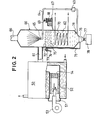
- Figure 2 shows a second embodiment of a combustion device according to the invention.
- Reference 50 denotes a domestic boiler of arbitrary known kind, into the furnace 51 of which a tubular member 52 of refractory material has been fitted in such a manner that the flame from an oil burner 53 will be directed axially thereinto.
- a porous slab 54 is fitted in the exit end of the tube.
- This slab may be composed of the same type of bodies 18, which are provided as separate elements in the hopper 15 of Figure 1, but which here have been bound together to a porous slab with a diameter corresponding to the internal diameter of the tube 52.
- the tube 52 will, in use, be maintained in incandescent state and the slab 54 will act in the same way as the bodies 18 in Figure 1, i.e. at operating temperature it will efficiently consume possible soot particles generated during start-up of the burner, or during occasional disturbances thereof.
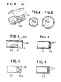
- the tube 52 may be manufactured in two halves 52a, as illustrated in Figure 3. The halves being individually introduced into the furnace, and built together therein.
- the tube 52, as well as the slab 54 may be formed in different ways in order to fit into furnaces of varying size and shape.
- Figure 6 shows an embodiment, where the tube is composed of two halves 52d and 52e, of which the latter is shorter than the former, so a downwardly directed exit opening 55 is formed.
- the exit end of the tube is closed by a plate 56, which forces the gases to deviate downwardly, to pass out below its lower edge.
- the embodiment according to Figure 7 shows a member 54a comprising obliquely disposed plates 57, which form a kind of grid.
- the member 54b is formed by funnel shaped elements 58, which are cast together into a slab having a diameter suited to the internal diameter of tube 52.
- the elements 58 are positioned so the desired flow area is obtained, without any direct through passage.
- a forward funnel directs in other words the gas flow towards the envelope faces of following funnels.
- member 54c in the exit end of tube 52 is formed as a mesh of ceramic fibers.
- the combustion gases are conveyed from the boiler 50 to a column 60 by way of a conduit 61.
- the chamber 62 below the connection of conduit 61 forms a recipient for neutralizing fluid.
- a pump 63 forces, by way of a pipe 64, fluid to a nozzle 65, which is located centrally in the column, above conduit 61.
- the nozzle is adapted to spray the fluid in the form of a hollow cone in the direction of flow of the gases on their way to an exit 66.
- a neutralizing agent for instance MgO
- MgO is added to the fluid in chamber 62 from a distributor 67.
- the agent is stored in a fine-mesh basket 68, and a certain amount of water is continuously drawn off from pipe 64 through a branch pipe 69, and is made to pass the distributor.
- a satisfactory quantity of the agent is dissolved and added to the fluid in chamber 62.
- a coil 70 is located in chamber 62 to take care of the residual heat in the same manner as has been mentioned in connection with coil 34 i Figure 1.
- a conduit 71 is connected to the lower end of chamber 62 and is brought upwards to a highest, desired fluid level 72 in the chamber.
- the end of the conduit is formed as a 360° loop 73 having a downwardly directed discharge 74.
- Sludge formed during the neutralization is collected in a pocket 76 below the column 60, and may intermittently be drained off to a recipient 78 by way of a valve 77.
- the tubes 52, as well as the inserts 54 may be modified in many ways, above those shown, and the column 60 need not be vertically placed, but can be mounted in an inclined flue passage.
- the spraying of fluid in the gas flow can be brought about by a number of nozzles arranged to distribute the fluid with, against or transversely to the direction of gas flow.
Landscapes
- Engineering & Computer Science (AREA)
- Chemical & Material Sciences (AREA)
- Mechanical Engineering (AREA)
- General Engineering & Computer Science (AREA)
- General Chemical & Material Sciences (AREA)
- Environmental & Geological Engineering (AREA)
- Biomedical Technology (AREA)
- Analytical Chemistry (AREA)
- Health & Medical Sciences (AREA)
- Oil, Petroleum & Natural Gas (AREA)
- Chemical Kinetics & Catalysis (AREA)
- Physics & Mathematics (AREA)
- Thermal Sciences (AREA)
- Wick-Type Burners And Burners With Porous Materials (AREA)
- Feeding And Controlling Fuel (AREA)
- Combustion Of Fluid Fuel (AREA)
- Treating Waste Gases (AREA)
Applications Claiming Priority (2)
| Application Number | Priority Date | Filing Date | Title |
|---|---|---|---|
| SE8203757A SE8203757L (sv) | 1982-06-17 | 1982-06-17 | Forfarande och anordning for forbrenning av flytande brensle |
| SE8203757 | 1982-06-17 |
Publications (2)
| Publication Number | Publication Date |
|---|---|
| EP0097631A2 true EP0097631A2 (de) | 1984-01-04 |
| EP0097631A3 EP0097631A3 (de) | 1984-10-31 |
Family
ID=20347090
Family Applications (1)
| Application Number | Title | Priority Date | Filing Date |
|---|---|---|---|
| EP83850160A Withdrawn EP0097631A3 (de) | 1982-06-17 | 1983-06-09 | Verfahren und Vorrichtung zum Verbrennen von fliessfähigem Brennstoff |
Country Status (5)
| Country | Link |
|---|---|
| EP (1) | EP0097631A3 (de) |
| DK (1) | DK275583A (de) |
| FI (1) | FI832140L (de) |
| NO (1) | NO832186L (de) |
| SE (1) | SE8203757L (de) |
Cited By (7)
| Publication number | Priority date | Publication date | Assignee | Title |
|---|---|---|---|---|
| EP0151398A1 (de) * | 1984-01-18 | 1985-08-14 | DEUTSCHE FORSCHUNGSANSTALT FÜR LUFT- UND RAUMFAHRT e.V. | Verfahren und Vorrichtung zur Rauchgasentschwefelung bei Heizölfeuerungen |
| EP0152742A1 (de) * | 1984-01-16 | 1985-08-28 | Neoxan Ag | Verfahren und Vorrichtung zum Reinigen der Abgase von Feuerungsanlagen, insbesondere von solchen bei Ein- und Mehrfamilienhäusern und dergleichen |
| EP0164098A3 (de) * | 1984-06-06 | 1986-12-03 | Willy Ufer | Wärmetauscher |
| EP0233971A1 (de) * | 1986-02-24 | 1987-09-02 | NTG Neue Technologien GmbH & Co. KG | Verfahren zur Rauchgasabreinigung aus Ölbefeuerten Hausheizungsanlagen |
| EP0208930A3 (de) * | 1985-06-18 | 1988-02-24 | Nikolaus Reininger | Wärmeaustauscher mit Speicher |
| EP0864352A3 (de) * | 1997-03-10 | 1999-01-07 | Deutsches Zentrum für Luft- und Raumfahrt e.V. | Verfahren zur Reinigung eines Abgases einer Feuerungsanlage |
| EP1170557A3 (de) * | 2000-07-03 | 2003-07-30 | Lars Ingvar Ollandt | Anordnung zur Wärmeerzeugung |
Family Cites Families (10)
| Publication number | Priority date | Publication date | Assignee | Title |
|---|---|---|---|---|
| FR2183620A1 (en) * | 1972-05-12 | 1973-12-21 | Vitenko Andrew | Smoke cleaning appts - having annular smoke conduits around periphery of filter block for providing extra filter surfaces |
| US3895918A (en) * | 1973-01-16 | 1975-07-22 | James H Mueller | High efficiency, thermal regeneration anti-pollution system |
| JPS5236610B2 (de) * | 1974-05-09 | 1977-09-17 | ||
| LU78800A1 (de) * | 1977-12-30 | 1979-07-20 | Arbed | Verfahren zur behandlung fremd-bzw.schadstoffbeladener gasgemische,wie insbesondere luft |
| US4192659A (en) * | 1978-08-07 | 1980-03-11 | The Trane Company | Method for hot gas cooling and gaseous contaminant removal |
| US4258017A (en) * | 1979-07-26 | 1981-03-24 | Uop Inc. | Vanadium removal from furnace gases |
| DE3002409A1 (de) * | 1980-01-24 | 1981-07-30 | Ing.(grad.) Heinz 4390 Gladbeck Hölter | Geruchsbeseitigungsfilter |
| DE3005431C2 (de) * | 1980-02-14 | 1986-08-21 | Klaus-Jürgen Dipl.-Ing. 2081 Hetlingen Möhlenbeck | Verfahren zur Ausnutzung des Brennwertes von festen, flüssigen oder gasförmigen Brennstoffen durch Rückgewinnung der in Verbrennungsabgasen enthaltenen Energie und Vorrichtung zur Durchführung des Verfahrens |
| JPS56122011U (de) * | 1980-02-19 | 1981-09-17 | ||
| AU559254B2 (en) * | 1981-03-05 | 1987-03-05 | Westinghouse Electric Corporation | Catalytic gas turbine combustor fuel supply |
-
1982
- 1982-06-17 SE SE8203757A patent/SE8203757L/ not_active Application Discontinuation
-
1983
- 1983-06-09 EP EP83850160A patent/EP0097631A3/de not_active Withdrawn
- 1983-06-14 FI FI832140A patent/FI832140L/fi not_active Application Discontinuation
- 1983-06-15 DK DK275583A patent/DK275583A/da not_active Application Discontinuation
- 1983-06-16 NO NO832186A patent/NO832186L/no unknown
Cited By (7)
| Publication number | Priority date | Publication date | Assignee | Title |
|---|---|---|---|---|
| EP0152742A1 (de) * | 1984-01-16 | 1985-08-28 | Neoxan Ag | Verfahren und Vorrichtung zum Reinigen der Abgase von Feuerungsanlagen, insbesondere von solchen bei Ein- und Mehrfamilienhäusern und dergleichen |
| EP0151398A1 (de) * | 1984-01-18 | 1985-08-14 | DEUTSCHE FORSCHUNGSANSTALT FÜR LUFT- UND RAUMFAHRT e.V. | Verfahren und Vorrichtung zur Rauchgasentschwefelung bei Heizölfeuerungen |
| EP0164098A3 (de) * | 1984-06-06 | 1986-12-03 | Willy Ufer | Wärmetauscher |
| EP0208930A3 (de) * | 1985-06-18 | 1988-02-24 | Nikolaus Reininger | Wärmeaustauscher mit Speicher |
| EP0233971A1 (de) * | 1986-02-24 | 1987-09-02 | NTG Neue Technologien GmbH & Co. KG | Verfahren zur Rauchgasabreinigung aus Ölbefeuerten Hausheizungsanlagen |
| EP0864352A3 (de) * | 1997-03-10 | 1999-01-07 | Deutsches Zentrum für Luft- und Raumfahrt e.V. | Verfahren zur Reinigung eines Abgases einer Feuerungsanlage |
| EP1170557A3 (de) * | 2000-07-03 | 2003-07-30 | Lars Ingvar Ollandt | Anordnung zur Wärmeerzeugung |
Also Published As
| Publication number | Publication date |
|---|---|
| FI832140A7 (fi) | 1983-12-18 |
| FI832140A0 (fi) | 1983-06-14 |
| SE8203757L (sv) | 1983-12-18 |
| DK275583D0 (da) | 1983-06-15 |
| NO832186L (no) | 1983-12-19 |
| DK275583A (da) | 1983-12-18 |
| FI832140L (fi) | 1983-12-18 |
| EP0097631A3 (de) | 1984-10-31 |
Similar Documents
| Publication | Publication Date | Title |
|---|---|---|
| US4289730A (en) | Furnace with flue gas condensate neutralizer | |
| US4999167A (en) | Low temperature Nox /Sox removal apparatus | |
| US4309947A (en) | Mounting arrangement for condensate neutralizer in a furnace | |
| EP0008568A1 (de) | Kessel zum Aufheizen eines Wärmetransportmittels in einem Heizsystem | |
| US3736234A (en) | High-purity distilled water producing apparatus | |
| US1866193A (en) | Purification of furnace or other gases | |
| US4588535A (en) | Installation for the treatment of combustion gases | |
| US4753220A (en) | Direct contact water heater | |
| EP0097631A2 (de) | Verfahren und Vorrichtung zum Verbrennen von fliessfähigem Brennstoff | |
| KR980001841A (ko) | 폐수처리장치 | |
| DE3120098A1 (de) | Wassererhitzungsgeraet | |
| US5570644A (en) | Anti-pollution system | |
| US2045519A (en) | Purification of gases | |
| KR101943914B1 (ko) | 습식정화 필터링장치 및 이를 포함하는 배기가스 정화시스템 | |
| FI71613C (fi) | Anordning vid braennkammare foer foerbraenning av fast braensle. | |
| JP2006105467A (ja) | 給湯装置 | |
| RU2006739C1 (ru) | Теплоутилизационное устройство | |
| US4601654A (en) | Pulse combustion apparatus | |
| EP0191147B1 (de) | Heizkessel für Öl- oder Gasfeuerung | |
| JPS5857649B2 (ja) | 燃焼装置の廃ガス熱を利用する装置 | |
| CN215892300U (zh) | 一种蒸汽机 | |
| JP3054259B2 (ja) | 焼却装置 | |
| TWI572773B (zh) | Dust collection equipment and methods for improving atmospheric warming and air pollution | |
| CN208720237U (zh) | 一种垃圾焚烧用废气处理装置 | |
| CN213955348U (zh) | 一种余热锅炉自控设备 |
Legal Events
| Date | Code | Title | Description |
|---|---|---|---|
| PUAI | Public reference made under article 153(3) epc to a published international application that has entered the european phase |
Free format text: ORIGINAL CODE: 0009012 |
|
| AK | Designated contracting states |
Designated state(s): AT CH DE LI NL SE |
|
| PUAL | Search report despatched |
Free format text: ORIGINAL CODE: 0009013 |
|
| AK | Designated contracting states |
Designated state(s): AT CH DE LI NL SE |
|
| STAA | Information on the status of an ep patent application or granted ep patent |
Free format text: STATUS: THE APPLICATION IS DEEMED TO BE WITHDRAWN |
|
| 18D | Application deemed to be withdrawn |
Effective date: 19851011 |