EP0138738A2 - Vorrichtung zum Trennen der Walzen eines Satinierkalanders - Google Patents
Vorrichtung zum Trennen der Walzen eines Satinierkalanders Download PDFInfo
- Publication number
- EP0138738A2 EP0138738A2 EP84630157A EP84630157A EP0138738A2 EP 0138738 A2 EP0138738 A2 EP 0138738A2 EP 84630157 A EP84630157 A EP 84630157A EP 84630157 A EP84630157 A EP 84630157A EP 0138738 A2 EP0138738 A2 EP 0138738A2
- Authority
- EP
- European Patent Office
- Prior art keywords
- rolls
- shifting
- pawls
- relation
- relieving
- Prior art date
- Legal status (The legal status is an assumption and is not a legal conclusion. Google has not performed a legal analysis and makes no representation as to the accuracy of the status listed.)
- Granted
Links
- 238000000034 method Methods 0.000 claims abstract description 12
- 239000000725 suspension Substances 0.000 claims abstract description 11
- 230000000694 effects Effects 0.000 claims description 3
- 210000002832 shoulder Anatomy 0.000 description 26
- 238000003490 calendering Methods 0.000 description 15
- 230000000295 complement effect Effects 0.000 description 2
- 230000007257 malfunction Effects 0.000 description 2
- 238000012986 modification Methods 0.000 description 2
- 230000004048 modification Effects 0.000 description 2
- 230000000717 retained effect Effects 0.000 description 2
- 238000000926 separation method Methods 0.000 description 2
- 229910001018 Cast iron Inorganic materials 0.000 description 1
- 229920000742 Cotton Polymers 0.000 description 1
- 230000000712 assembly Effects 0.000 description 1
- 238000000429 assembly Methods 0.000 description 1
- 230000008878 coupling Effects 0.000 description 1
- 238000010168 coupling process Methods 0.000 description 1
- 238000005859 coupling reaction Methods 0.000 description 1
- 230000000254 damaging effect Effects 0.000 description 1
- 230000001066 destructive effect Effects 0.000 description 1
- 239000012530 fluid Substances 0.000 description 1
- 238000009499 grossing Methods 0.000 description 1
- 239000000463 material Substances 0.000 description 1
Images

Classifications
-
- B—PERFORMING OPERATIONS; TRANSPORTING
- B30—PRESSES
- B30B—PRESSES IN GENERAL
- B30B15/00—Details of, or accessories for, presses; Auxiliary measures in connection with pressing
- B30B15/04—Frames; Guides
-
- B—PERFORMING OPERATIONS; TRANSPORTING
- B30—PRESSES
- B30B—PRESSES IN GENERAL
- B30B3/00—Presses characterised by the use of rotary pressing members, e.g. rollers, rings, discs
- B30B3/04—Presses characterised by the use of rotary pressing members, e.g. rollers, rings, discs co-operating with one another, e.g. with co-operating cones
-
- D—TEXTILES; PAPER
- D21—PAPER-MAKING; PRODUCTION OF CELLULOSE
- D21G—CALENDERS; ACCESSORIES FOR PAPER-MAKING MACHINES
- D21G1/00—Calenders; Smoothing apparatus
- D21G1/002—Opening or closing mechanisms; Regulating the pressure
Definitions
- the present invention relates to supercalenders of the type wherein the rolls are adapted for limited separation from one another in one mode and are in calendering nipping engagement with one another in another mode.
- Supercalenders with which the present invention is concerned are well known in the art and comprise a substantial stack of calender rolls wherein separation of the rolls may be controlled either from the top or the bottom of the stack. Where control is from the bottom of the stack, a king roll at the bottom of the stack is moveable between a lowered position and a raised position. In the lowered position of the king roll, a substantial number of calender rolls thereabove separate from one another to provide gaps therebetween to facilitate threading a new web of material through the stack or to relieve any damaging effect of broke or creased web passing through the roll nips. As thus gapped, the opposite ends of the rolls are supported by their bearing structures on shoulders along upright suspension spindles at the opposite sides of the stack.
- each bearing structure at each end of each of the rolls may weigh from 4,000 to 5,000 pounds. Therefore, when the rolls are lifted to the nipping, calendering mode, and the bearing structures are in deadweight relation at each end of each roll, the deadweight end loads on the rolls tend to distort the rolls and thus distort nips between rolls from the ideal straight line. This distortion or warping oondi- tion is aggravated where, as is often desirable, fly rolls (i.e. guide rolls) are supported on the housings of the bearing structures.
- the present invention provides a method of operating a calender having a vertical stack of a plurality of rotary rolls, each of the rolls having bearing structure at each opposite end provided with a thrust shoul der cooperative with a stop shoulder on a respective suspension spindle at each end of the rolls, means for guiding the bearing structures for vertical movement, and means for vertically shifting the rolls between a lowered mode for spaced apart independent suspension by engagement of the thrust shoulders with the stop shoulders and a raised nipping mode relation with one another wherein the thrust shoulders are raised from the stop shoulders, and comprising relieving the weight of the bearing structures of the rolls in the raised nipping mode relation of the rolls.
- the present invention provides a calender having a vertical stack of a plurality of rotary rolls, each of the rolls having bearing structure at each opposite end provided with a thrust shoulder cooperative with a stop shoulder on a respective suspension spindle at each end of the rolls, means for guiding the bearing structures for vertical movement, and means for vertically shifting the rolls between a lowered mode for spaced apart independent suspension by engagement of the thrust shoulders with the stop shoulders and a raised nipping mode relation with one another wherein the thrust shoulders are raised from the stop shoulders, and comprising means for relieving the weight of the bearing structures from the rolls in the raised nipping mode relation, and means for operating the relieving means.
- FIGs. 1 and 2 one side of a supercalender is depicted wherein a vertical stack of calender rolls 10 is supported in respect to a supporting frame 11. Only one side of the calender is depicted, and it will be understood that the opposite side will be substantially mirror image of the illustrated side, and the description will assume such substantial similarity of both sides, and thus the substantial similarity of the structures involved at each opposite end of each of the calender rolls in the stack 10.
- the calender stack 10 comprises a lowermost king roll 12 and thereabove a series of filled (i.e. composed of a core supporting a concentric pack of cotton, paper or fibrous disks) rolls 13, and cast iron rolls 14 which, in general are alternated in the stack, except near the center of the stack where a pair of the filled rolls 13 have nipping relation with one another so that a web W being calendered will be exposed to the smoothing action of these filled rolls on both sides.
- a head roll 15 (Fig. 1) bears downwardly on the stack of rolls in the calendering mode for attaining substantially uniform nipping pressure between all of the rolls in the stack.
- the topmost roll serves not only as a pressure roll but also as a lifting roll by which all of the rolls except the lowermost roll are lifted into nip separating relation
- the preferred arrangement shown in Figs. 1 and 2 has the lower or king roll 12 in control of both the calendering mode as shown in Fig. 1 and the open roll mode shown in Fig. 2.
- supporting bearing means 17 at each end of the king roll 12 have associated therewith upwardly thrusting hydraulic plungers 18 of hydraulic cylinders 19 adapted to thrust the king roll 12 upwardly as shown by directional arrow Fig. 1 for the calendering mode, and to drop the king roll 12 rapidly for the open roll mode as shown in Fig. 2.
- the top roll 15 has its bearing structures 20 at each opposite end adapted to be thrust downwardly by means a respective hydraulic actuator piston plunger 21 having its hydraulic cylinder 22 mounted on the frame 11 in each instance.
- the actuators 22 are adapted to be activated after the hydraulic actuators 19 have raised the king roll 12 into the calendering mode for attaining the desired substantial uniformity of calendering load on the stack. As shown in Fig. 2, in the open roll mode the actuators 22 are inactivated.
- a vertical rail 23 is provided which extends the full lengtl from to bottom of the stack and is adapted for slidable tracking engagement with the housings of the bearings of the several rolls.
- Each of the rolls 13 and 14 has a similar bearing structure 24. All of the bearing housings for all of the bearing structures 24 and the bearing structures 117 and 20 may be slidably engaged with the rail 23 as typically illustrated in Fig. 3.
- the rail 23 is secured to the frame 11 as by means of bolts 25 at suitable intervals there along.
- Bearing housing 27 has vertical bearing surfaces 27 in tracking engagement with the rail 23 in cooperation with retainer plates 28 secured to the housing 27 by means of bolts 29.
- Roller bearings 30 support the associated journal 31 of the calender roll on the bearing housing 27 which is of a mass and durability suitable for the purpose.
- Each of the bearing housings 27 for each of the bearing structures 20 and 24 has an integral yoke 32 within which the shank of a threaded screw spindle 33 is received, the yoke providing a thrust shoulder facing toward and engageable with an underlying supporting stop shoulder 34 in the form of a stop nut threadedly engaged on the spindle 33 and readily adjustable therealong.
- Each of the stop nuts 34 is adapted to be adjusted to attain the desired spacing between its associated roll and the contiguous rolls. In a preferred relationship, such spacing may be progressively greater from the uppermost roll nip to the lowermost roll nip.
- the spacing may be about 12.7 mm , and the spacing of each successive nip downwardly in the stack may increase by about 5.07 mm increment so that in a stack having the number of rolls shown the lowermost nip spacing in the open condition of the rolls may be about 53.34 mm .
- Each of the spindles 33 is thoroughly anchored at the top of the frame 11.
- bearing structures 20 and 24 may be heavy enough in and of themselves to cause a nip distortion by reason of their deadweight in the closed nipping roll mode as depicted in Fig. 1, the problem is aggravated where it may be preferred to mount fly roller assemblies 35 on the housings 27 of the bearing structures for each of the rolls above the king roll 12.
- Such mounting of the fly rollers 35 (also sometimes referred to as guide rollers) is desirable because thereby the fly rollers remain in the most desirable alignment with respect to the associated calender roll in each instance, and when the rolls in the stack are rapidly dropped to open the nips, there is minimum, if any, distorting tension of the web W.
- the weight of the bearing structures 20 and 24 is relieved from the rolls 13,14 and 15 in the raised nipping mode relation of the calender rolls, that is,the mode illustrated in Fig. 1.
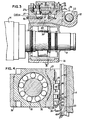
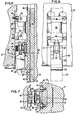
- This is effected, for example, by means illustrated in Figs. 3-7, including rack means 37 conveniently in the form of an elongate rack bar associated with each of the rack members 23 and selectively engageable by a pawl 38 carried by the bearing housing 27.
- rack means 37 conveniently in the form of an elongate rack bar associated with each of the rack members 23 and selectively engageable by a pawl 38 carried by the bearing housing 27.
- this arrangement prevails with equal effect at each side of the calender stack, and more particularly at each of the ends of the calender rolls.
- the arrangement is such that when the king roll 12 raises the calender rolls thereabove into their nipping, calendering relation, the rack bar 37 is engaged by the pawl 38 as shown in dot dash outline in Fig. 5.
- the deadweight load of the associated bearing structure is relieved from the associated end of the calender roll.
- the pawls 38 are adapted to freely disengage from the rack bars 37.
- each of the rack bars 37 is slidably mounted in a complementary vertical recess 39 in the associated track member 23 and which is deep enough to receive the rack bar with rack teeth 40 thereof about flush with the outer face of the track member 23, as best visualized in Figs. 3 and 7.
- Retainer strips 41 mounted in offset grooves 42 at the outer sides of the recess 39 and retained in overlapping retaining relation to lateral shoulders 43 extending longitudinally on the rack bar 37 inwardly alongside the rack teeth 40, are secured in place by means of screws 44.
- the racks bars 37 are adapted to thrust at each side of the calender stack against a stop shoulder 45 (Fig. 1) provided by the uppermost of a pair of vertically spaced runner bosses 45 integral with the housing of the bearing structure 17 of the king roll 12. These runner bosses 45 are in engagement with the track member 23 in similar fashion as shown in Fig. 3 for the bearing structure housing 27.
- a stop shoulder 45 FIG. 1
- the rack bars 37 are shifted upwardly in their track recess 39.
- the rack bars 37 follow , at least by gravitational bias, their associated shoulder bosses 45 and descend therewith as guided in their tracks recesses.
- Means are provided for controlling the pawls 38 individually in a manner to assure that the pawls will engage the rack teeth in each instance only when the calender roll system is ready for the deadweight relief function of the pawl and rack structure.
- each of the pawls 38 is carried by the lower end portion of a piston rod 47 of a rectilinear hydraulic actuator 48 mounted in vertical position to the bearing housing 27 in each instance.
- the pawl 38 is pivotally attached to the piston rod or plunger 47 by means of an ear 50 (Figs.
- pawl 38 is positively swung toward the adjacent face of the housing 27 and is held in a position where the pawl finger 53 is clear of the rack teeth 40.
- biasing means comprising a spring 59 which is compressed by the shoulder 58.
- Hydraulic fluid for operating the actuator 48 is delivered to opposite ends of its piston 60 through an upper inlet 61 and a lower inlet 62 (Fig. 5) to which respective alternating hydraulic pressure /relief conduits 63 and 64 are connected.
- Operation of the hydraulic actuators 48 is coordinated with operation of the hydraulic actuators 19 for the king roll 12 and the actuators 22 for the top or head roll 50.
- the pawl actuators 48 retract the pawls.
- the pawl actuators 48 are operated to drive the pawls 38 downwardly.
- the biasing springs 59 swing the pawls 38 toward the associated racks 37 so that the pawl fingers 53 will engage with one of the teeth 40 of the rack.
- safety means comprising a proximity switch 65 (Fig. 5) is provided for each of the pawls 38 to monitor its retracting performance. If any of the pawls 38 does not properly retract, then this will be signalled at a control station, and the malfunction may be traced.
- This safety feature avoids the possibility that any pawl may remain in engagement with the rack 37 in the separated roll mode, whereby on lifting of the stack toward the calendering, nipping mode the entire weight of the associated roll might be imposed through the malfunctioning pawl onto the associated rack 37. Overburdening and possibly destructive imposition of weight on the rack 37 is thus avoided.
Landscapes
- Engineering & Computer Science (AREA)
- Mechanical Engineering (AREA)
- Paper (AREA)
- Casting Or Compression Moulding Of Plastics Or The Like (AREA)
- Folding Of Thin Sheet-Like Materials, Special Discharging Devices, And Others (AREA)
- Spinning Or Twisting Of Yarns (AREA)
- Types And Forms Of Lifts (AREA)
- Treatment Of Fiber Materials (AREA)
Applications Claiming Priority (2)
| Application Number | Priority Date | Filing Date | Title |
|---|---|---|---|
| US543167 | 1983-10-19 | ||
| US06/543,167 US4501197A (en) | 1983-10-19 | 1983-10-19 | Supercalender edge nip relieving |
Publications (3)
| Publication Number | Publication Date |
|---|---|
| EP0138738A2 true EP0138738A2 (de) | 1985-04-24 |
| EP0138738A3 EP0138738A3 (en) | 1987-01-21 |
| EP0138738B1 EP0138738B1 (de) | 1989-07-05 |
Family
ID=24166864
Family Applications (1)
| Application Number | Title | Priority Date | Filing Date |
|---|---|---|---|
| EP84630157A Expired EP0138738B1 (de) | 1983-10-19 | 1984-10-12 | Vorrichtung zum Trennen der Walzen eines Satinierkalanders |
Country Status (13)
| Country | Link |
|---|---|
| US (1) | US4501197A (de) |
| EP (1) | EP0138738B1 (de) |
| JP (1) | JPS6099093A (de) |
| KR (1) | KR880000408B1 (de) |
| AR (1) | AR241815A1 (de) |
| BR (1) | BR8404985A (de) |
| CA (1) | CA1238508A (de) |
| DE (2) | DE3478867D1 (de) |
| ES (1) | ES8604325A1 (de) |
| FI (1) | FI79573C (de) |
| IN (1) | IN162485B (de) |
| MX (1) | MX162159A (de) |
| PH (1) | PH21517A (de) |
Cited By (4)
| Publication number | Priority date | Publication date | Assignee | Title |
|---|---|---|---|---|
| EP0149959A3 (en) * | 1984-01-23 | 1987-01-28 | Beloit Corporation | Supercalender nip relieving arrangement |
| EP0330955A3 (de) * | 1988-03-04 | 1990-01-31 | Sulzer-Escher Wyss Gmbh | Verfahren und Glättwerk zum Glätten einer Materialbahn und insbesondere einer Papierbahn |
| GB2237295A (en) * | 1989-10-28 | 1991-05-01 | Escher Wyss Gmbh | Method for the positioning of calender rollers and calender for carrying out the method |
| DE102007029461A1 (de) | 2007-06-26 | 2009-01-08 | Voith Patent Gmbh | Kalandervorrichtung |
Families Citing this family (11)
| Publication number | Priority date | Publication date | Assignee | Title |
|---|---|---|---|---|
| JPS6290394A (ja) * | 1985-10-14 | 1987-04-24 | 石川島播磨重工業株式会社 | 多段式ス−パ−カレンダの通紙方法 |
| JPS62183727A (ja) * | 1986-02-10 | 1987-08-12 | 松下電器産業株式会社 | 電気掃除機 |
| DE3702245C3 (de) * | 1987-01-27 | 1993-12-23 | Kleinewefers Gmbh | Kalander |
| FI81633C (fi) * | 1988-01-13 | 1990-11-12 | Valmet Paper Machinery Inc | Anlaeggning i valsverket av en superkalander. |
| FI86450C (fi) * | 1989-10-25 | 1992-08-25 | Ahlstroem Valmet | Funktionsanordning av modulkonstruktion foer valsarna i en maskinkalander. |
| DE4026774A1 (de) * | 1990-08-24 | 1992-03-05 | Voith Gmbh J M | Mehrwalzen-glaettwerk |
| DE19711241C2 (de) * | 1997-03-18 | 2002-08-29 | Voith Paper Patent Gmbh | Kalander für Papier und ähnliches Bahnmaterial |
| FI114405B (fi) * | 1999-09-24 | 2004-10-15 | Metso Paper Inc | Kalanteri ja menetelmä paperi- tai kartonkirainan kalanteroimiseksi |
| CN100385071C (zh) * | 2004-01-14 | 2008-04-30 | 淄博恒星机电设备有限公司 | 全液压分区可控中高超级压光机 |
| CN105568735B (zh) * | 2016-02-04 | 2017-08-01 | 淄博泰鼎造纸机械有限公司 | 一种超级压光机的压光辊单元 |
| CN105544278B (zh) * | 2016-02-04 | 2017-06-16 | 淄博泰鼎机械科技有限公司 | 一种超级压光机的滑座及超级压光机 |
Family Cites Families (11)
| Publication number | Priority date | Publication date | Assignee | Title |
|---|---|---|---|---|
| US2985100A (en) * | 1958-01-29 | 1961-05-23 | Beloit Iron Works | Calender stack |
| US3180251A (en) * | 1963-05-24 | 1965-04-27 | John Inglis Co Ltd | Calenders |
| AT261385B (de) * | 1963-12-18 | 1968-04-25 | Kleinewefers Soehne J | Druckhydraulikvorrichtung für Papier-Satinierkalander |
| US3369483A (en) * | 1965-04-14 | 1968-02-20 | Kleinewefers Soehne J | Adjusting device for fast venting and roller fine adjustment, especially for paper satining calenders |
| US3554118A (en) * | 1968-02-12 | 1971-01-12 | Tampella Oy Ab | Relief and raising device arrangement in multinip calender |
| GB1291086A (en) * | 1968-11-27 | 1972-09-27 | Kleinewefers Soehne J | Means for setting a roll gap |
| DE2101374C3 (de) * | 1971-01-13 | 1974-06-27 | Bruderhaus Maschinen Gmbh, 7410 Reutlingen | Kalander zum Bearbeiten von Papierbahnen |
| DE2423504A1 (de) * | 1974-05-15 | 1975-11-27 | Kleinewefers Ind Co Gmbh | Kalander, insbesondere zur bearbeitung von papierbahnen |
| DE2830733C3 (de) * | 1978-07-13 | 1982-05-06 | Kleinewefers Gmbh, 4150 Krefeld | Vorrichtung zum schnellen Trennen der Walzen eines Kalanders |
| JPS5557097A (en) * | 1978-10-16 | 1980-04-26 | Kleinewefers Gmbh | Method and apparatus for rapidly separating calender roll |
| FI65106C (fi) * | 1980-06-10 | 1984-03-12 | Valmet Oy | On-machine superkalander foer en pappersmaskin |
-
1983
- 1983-10-19 US US06/543,167 patent/US4501197A/en not_active Expired - Lifetime
-
1984
- 1984-09-05 CA CA000462434A patent/CA1238508A/en not_active Expired
- 1984-09-14 FI FI843601A patent/FI79573C/fi not_active IP Right Cessation
- 1984-10-03 BR BR8404985A patent/BR8404985A/pt not_active IP Right Cessation
- 1984-10-08 IN IN707/CAL/84A patent/IN162485B/en unknown
- 1984-10-09 MX MX202992A patent/MX162159A/es unknown
- 1984-10-12 DE DE8484630157T patent/DE3478867D1/de not_active Expired
- 1984-10-12 DE DE198484630157T patent/DE138738T1/de active Pending
- 1984-10-12 EP EP84630157A patent/EP0138738B1/de not_active Expired
- 1984-10-15 PH PH31342A patent/PH21517A/en unknown
- 1984-10-17 AR AR84298288A patent/AR241815A1/es active
- 1984-10-18 JP JP59217449A patent/JPS6099093A/ja active Granted
- 1984-10-18 KR KR1019840006475A patent/KR880000408B1/ko not_active Expired
- 1984-10-18 ES ES536840A patent/ES8604325A1/es not_active Expired
Cited By (4)
| Publication number | Priority date | Publication date | Assignee | Title |
|---|---|---|---|---|
| EP0149959A3 (en) * | 1984-01-23 | 1987-01-28 | Beloit Corporation | Supercalender nip relieving arrangement |
| EP0330955A3 (de) * | 1988-03-04 | 1990-01-31 | Sulzer-Escher Wyss Gmbh | Verfahren und Glättwerk zum Glätten einer Materialbahn und insbesondere einer Papierbahn |
| GB2237295A (en) * | 1989-10-28 | 1991-05-01 | Escher Wyss Gmbh | Method for the positioning of calender rollers and calender for carrying out the method |
| DE102007029461A1 (de) | 2007-06-26 | 2009-01-08 | Voith Patent Gmbh | Kalandervorrichtung |
Also Published As
| Publication number | Publication date |
|---|---|
| FI79573B (fi) | 1989-09-29 |
| FI843601A0 (fi) | 1984-09-14 |
| FI79573C (fi) | 1990-01-10 |
| FI843601L (fi) | 1985-04-20 |
| ES536840A0 (es) | 1986-01-16 |
| EP0138738A3 (en) | 1987-01-21 |
| KR880000408B1 (ko) | 1988-03-22 |
| BR8404985A (pt) | 1985-08-20 |
| JPS6137400B2 (de) | 1986-08-23 |
| AR241815A1 (es) | 1992-12-30 |
| IN162485B (de) | 1988-06-04 |
| DE3478867D1 (de) | 1989-08-10 |
| JPS6099093A (ja) | 1985-06-01 |
| CA1238508A (en) | 1988-06-28 |
| PH21517A (en) | 1987-11-10 |
| KR850003703A (ko) | 1985-06-26 |
| EP0138738B1 (de) | 1989-07-05 |
| DE138738T1 (de) | 1986-05-22 |
| ES8604325A1 (es) | 1986-01-16 |
| MX162159A (es) | 1991-04-03 |
| US4501197A (en) | 1985-02-26 |
Similar Documents
| Publication | Publication Date | Title |
|---|---|---|
| US4501197A (en) | Supercalender edge nip relieving | |
| CA1231573A (en) | Supercalender nip relieving arrangement | |
| EP0571581B1 (de) | Walzenpresse | |
| DE4110205C2 (de) | Walzenpresse | |
| DE102005026100B4 (de) | Ziehkissenvorrichtung | |
| EP0035110B1 (de) | Kalander | |
| KR100347728B1 (ko) | 제지기계또는판지기계의프레스용컴팩트프레임조립체 | |
| EP0822289B2 (de) | Kalander | |
| US4986177A (en) | Apparatus for controlling the load/relief pressures in a calender | |
| FI81633C (fi) | Anlaeggning i valsverket av en superkalander. | |
| US5673617A (en) | Calendar for full and light calendering | |
| DE2224875C3 (de) | Vorrichtung zum Belasten und Trennen der Walzen eines der Bearbeitung von Bahnen, insbesondere von Papierbahnen, dienenden Walzensatzes | |
| EP1026316A2 (de) | Kalander für bahnförmige Materialien wie Papier | |
| US5022319A (en) | Apparatus for neutralizing overhanging loads | |
| US4266475A (en) | Positioning mechanism for calender rolls | |
| EP0029649B1 (de) | Positionierungsmechanismus für Kalanderwalzen | |
| FI69146C (fi) | Reglerbar superkalander | |
| JPH0237905A (ja) | 圧延機のパスライン調整装置 | |
| CN85103249A (zh) | 高度砑光机边缘夹头释放 | |
| JPS6355369B2 (de) | ||
| GB1361565A (en) | Method and apparatus relating to loading and separating rollers of a calender | |
| DE10297318T5 (de) | Walzenwechselvorrichtung | |
| JPS6016288B2 (ja) | 圧延機 | |
| CN118257153A (zh) | 一种超级压光机快速卸压机构 | |
| DE3942689C2 (de) | Kalander, speziell Superkalander |
Legal Events
| Date | Code | Title | Description |
|---|---|---|---|
| PUAI | Public reference made under article 153(3) epc to a published international application that has entered the european phase |
Free format text: ORIGINAL CODE: 0009012 |
|
| AK | Designated contracting states |
Designated state(s): DE FR GB IT SE |
|
| ITCL | It: translation for ep claims filed |
Representative=s name: RICCARDI SERGIO & CO. |
|
| DET | De: translation of patent claims | ||
| EL | Fr: translation of claims filed | ||
| PUAL | Search report despatched |
Free format text: ORIGINAL CODE: 0009013 |
|
| AK | Designated contracting states |
Kind code of ref document: A3 Designated state(s): DE FR GB IT SE |
|
| 17P | Request for examination filed |
Effective date: 19870217 |
|
| 17Q | First examination report despatched |
Effective date: 19880603 |
|
| GRAA | (expected) grant |
Free format text: ORIGINAL CODE: 0009210 |
|
| ITF | It: translation for a ep patent filed | ||
| AK | Designated contracting states |
Kind code of ref document: B1 Designated state(s): DE FR GB IT SE |
|
| REF | Corresponds to: |
Ref document number: 3478867 Country of ref document: DE Date of ref document: 19890810 |
|
| ET | Fr: translation filed | ||
| PLBE | No opposition filed within time limit |
Free format text: ORIGINAL CODE: 0009261 |
|
| STAA | Information on the status of an ep patent application or granted ep patent |
Free format text: STATUS: NO OPPOSITION FILED WITHIN TIME LIMIT |
|
| 26N | No opposition filed | ||
| ITTA | It: last paid annual fee | ||
| EAL | Se: european patent in force in sweden |
Ref document number: 84630157.0 |
|
| REG | Reference to a national code |
Ref country code: FR Ref legal event code: TP |
|
| REG | Reference to a national code |
Ref country code: GB Ref legal event code: 732E |
|
| REG | Reference to a national code |
Ref country code: GB Ref legal event code: IF02 |
|
| PGFP | Annual fee paid to national office [announced via postgrant information from national office to epo] |
Ref country code: GB Payment date: 20030929 Year of fee payment: 20 |
|
| PGFP | Annual fee paid to national office [announced via postgrant information from national office to epo] |
Ref country code: SE Payment date: 20031001 Year of fee payment: 20 |
|
| PGFP | Annual fee paid to national office [announced via postgrant information from national office to epo] |
Ref country code: FR Payment date: 20031009 Year of fee payment: 20 |
|
| PGFP | Annual fee paid to national office [announced via postgrant information from national office to epo] |
Ref country code: DE Payment date: 20031010 Year of fee payment: 20 |
|
| PG25 | Lapsed in a contracting state [announced via postgrant information from national office to epo] |
Ref country code: GB Free format text: LAPSE BECAUSE OF EXPIRATION OF PROTECTION Effective date: 20041011 |
|
| REG | Reference to a national code |
Ref country code: GB Ref legal event code: PE20 |
|
| EUG | Se: european patent has lapsed |