EP0136849A1 - Bandkassette - Google Patents
Bandkassette Download PDFInfo
- Publication number
- EP0136849A1 EP0136849A1 EP84306100A EP84306100A EP0136849A1 EP 0136849 A1 EP0136849 A1 EP 0136849A1 EP 84306100 A EP84306100 A EP 84306100A EP 84306100 A EP84306100 A EP 84306100A EP 0136849 A1 EP0136849 A1 EP 0136849A1
- Authority
- EP
- European Patent Office
- Prior art keywords
- cover
- tape cassette
- opening
- cassette
- cassette according
- Prior art date
- Legal status (The legal status is an assumption and is not a legal conclusion. Google has not performed a legal analysis and makes no representation as to the accuracy of the status listed.)
- Granted
Links
- 238000003780 insertion Methods 0.000 claims description 6
- 230000037431 insertion Effects 0.000 claims description 6
- 239000000428 dust Substances 0.000 description 3
- 230000000694 effects Effects 0.000 description 1
- 238000010348 incorporation Methods 0.000 description 1
- 238000005192 partition Methods 0.000 description 1
- 230000002265 prevention Effects 0.000 description 1
Images


Classifications
-
- G—PHYSICS
- G11—INFORMATION STORAGE
- G11B—INFORMATION STORAGE BASED ON RELATIVE MOVEMENT BETWEEN RECORD CARRIER AND TRANSDUCER
- G11B23/00—Record carriers not specific to the method of recording or reproducing; Accessories, e.g. containers, specially adapted for co-operation with the recording or reproducing apparatus ; Intermediate mediums; Apparatus or processes specially adapted for their manufacture
- G11B23/02—Containers; Storing means both adapted to cooperate with the recording or reproducing means
- G11B23/04—Magazines; Cassettes for webs or filaments
- G11B23/08—Magazines; Cassettes for webs or filaments for housing webs or filaments having two distinct ends
- G11B23/087—Magazines; Cassettes for webs or filaments for housing webs or filaments having two distinct ends using two different reels or cores
- G11B23/08707—Details
- G11B23/08735—Covers
Definitions
- the present invention relates to an improvement of tape cassettes and particularly pertains to a proposal for a tape cassette with a cover for proofing against dust and finger-printing, etc.
- the present invention intended to meet the aforementioned demands, has as its object providing tape cassettes of very simple structure and which permit use of both faces A and B.
- Further object of this invention is to prevent the cover from being mistakenly opened while being handled by means of a simple closed position locking mechanism. Since the cover is designed to be shifted with a click to the two positions, opened and closed, by means of a spring force and itself to be ensconsed after the operation, positioning and holding in the specified place for playing may be ensured similarly as in the case of conventional compact cassettes. On the cover, a spring force always urging it backward is applied while it is making the opening-closing operation, so that it moves between the two positions opened and closed with a minimum of locus. For this reason, the necessary space indide the tape recorder is minimized for effective miniaturization of equipments such as tape recorders, etc.
- leaf spring are used as the means for urging the cover backward and are composed to be pushed from the front of the rotary shaft, the springs may be held insdide a narrow space and because no coil spring is used, assibling work is facilitated and the internal space of the tape cassette may be effectively utilized.
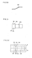
- FIG. 1 shows a perspective view of an embodiment of a conventional audio tape cassette (the so-called compact cassette) in which the tape is seen in the interior of the opening, a state of the tape being nearly exposed to dust, etc.
- a conventional audio tape cassette the so-called compact cassette
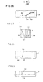
- FIG. 2 is a perspective view showing the closed state of the tape cassette in an embodiment of this invention
- FIG. 3 represents its side view
- FIG. 4 a side view showing its opened state.
- 1 denotes a cassette body; 2, the cassette upper hald; and 3, the cassette lower half.
- Numeral 4 designates a cover; 5, the side part of the cover 4; 6, a protuberance provided on the side part 5 of the cover; 7, a rotary shaft projecting inward of the side 5 of the cover; 8, a hole engaging with the rotary shaft 7, which is formed in the shape of a triangle which is tapering rearward to a position where the cassette upper half 2 and the cassette lower half 3 abut on each other.
- Numeral 9 stands for a spring one end of which is hooked on the rotary shaft 7 always to urge the cover 4, backward.
- Numeral 10 is designates a pin for hooking the spring which is integrally formed with the cassette lower half 3; and 11 openings at the front of the cassette.
- FIG. 5 is a top view showing the interior of the cassette in which a reel-to-reel tape is housed.
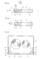
- FIG. 6 is a side sectional view showing details of the essential part of the cover, H representing the total thickness of the front part of the cassette; and L, the distance from the inside surface of the cover 4 to the rotary shaft 7.
- H representing the total thickness of the front part of the cassette
- L the distance from the inside surface of the cover 4 to the rotary shaft 7.
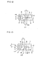
- FIG. 7 is a side sectional view showing the essential part of an embodiment of a cassette recorder so designed that the opening-closing of the cover of this cassette, when used, may be automatically done interlocked with its putting-in and -out of the cassette recorder, 13 representing cassette inserting hole, 14 cassette insertion guide, 15 a projection having a bevel for opening the cover, which is provided on the side of the insertion guide, and 16 a part to be engaged for closing the cover being in its opened state when delivering the cassette.
- the cover can also be opened downward.
- the cover 4 is always opened upward from the equipment.
- the opening-closing operations may be automatically performed interlocked to the putting-in and -out of the cassette by utilizing a cassette insertion guide as shown in F I G. 7.
- a cassette insertion guide as shown in F I G. 7.
- the cover 4 itself may be ensconsed, being perfectly close-fitted on the upper or lower surface of the cassette.
- the right-most end of the engaging hole 8 should be placed at the center of the cassette thickness so that the rotary shaft 7 is always brought to the center of the cassette thickness and, moreover, only a little clearance should be provided to allow.close-fitting of the cover 4 on the opening under the closed state.
- FIG. 8 is a side sectional view showing the essential part of a second embodiment of this invention, in which the engaging hole is in the shape of approximately V which is tapering rearward.
- the aforementioned embodiment concerns a cassette whose cover permits opening either upwardly or downwardly, but this arrangement may be applicable to a cassette whose cover is opened only in one direction, for which the engaging hole may have nearly the half size configuration.
- FIG. 9 is a side sectional view showing the essential part of a third embodiment of this invention. It is provided with a locking mechanism which prevents easy opening of the cover in its closed state while being handled.
- FIG. 9 shows the cover being in the closed state, while the figure by two dots and a dash alternating lines represent its opened state.
- Numeral 17 designates a recess provided on the opening; 18, a protrusion; and 19, recesses provided on the upper and the lower surfaces of the cassette, with a tapered surface 19a formed at the forward portion, in which the protrusion of the cover being in its opened state enters.
- the recess 19 is omitted and the protrusion 18 is to be put on the upper or the lower surface of the cassette body 1.
- the configuration and size are a little larger, but the upper and the lower edges of the cover are more readily utilizable as the abutting portions, as the cover is brought from its oepend state to its closed state.
- the recess 17 to engage with the protrusion 18 of the cover 4 is provided on each partition frame formed between openings at the opening surface.
- the opening part itself may be used as the recess.
- the recess to engage with the whole of the inside surface of the cover 4 may be formed all over the front of the opening surface.
- the embodiment of this invention permits holding.of leaf spring on the inside wall surface of the cassette in close contact therewith and is, therefore, very effective for application in a narrow space inside the cassette.
- the studded member 30 may be tapered to be upwardly opening or the studded member is studded in one cassette half only, to a higher than the side wall of the cassette half, or assembling improvement may be designed by shifting its position from both upper and lower halves and extending it inside opposite halves.
Landscapes
- Packaging Of Annular Or Rod-Shaped Articles, Wearing Apparel, Cassettes, Or The Like (AREA)
Applications Claiming Priority (12)
| Application Number | Priority Date | Filing Date | Title |
|---|---|---|---|
| JP16445283A JPS6055574A (ja) | 1983-09-06 | 1983-09-06 | カセツト |
| JP164452/83 | 1983-09-06 | ||
| JP19116583A JPS6083283A (ja) | 1983-10-13 | 1983-10-13 | 蓋つきカセツト |
| JP191165/83 | 1983-10-13 | ||
| JP211329/83 | 1983-11-10 | ||
| JP21132983A JPS60103571A (ja) | 1983-11-10 | 1983-11-10 | 蓋つきテ−プカセツト |
| JP233057/83 | 1983-12-09 | ||
| JP23305783A JPS60125981A (ja) | 1983-12-09 | 1983-12-09 | 蓋つきテ−プカセット |
| JP82168/84 | 1984-04-24 | ||
| JP8216884A JPS60226082A (ja) | 1984-04-24 | 1984-04-24 | テ−プカセツト |
| JP82167/84 | 1984-04-24 | ||
| JP8216784A JPS60226081A (ja) | 1984-04-24 | 1984-04-24 | テ−プカセツト |
Publications (2)
| Publication Number | Publication Date |
|---|---|
| EP0136849A1 true EP0136849A1 (de) | 1985-04-10 |
| EP0136849B1 EP0136849B1 (de) | 1988-11-30 |
Family
ID=27551551
Family Applications (1)
| Application Number | Title | Priority Date | Filing Date |
|---|---|---|---|
| EP84306100A Expired EP0136849B1 (de) | 1983-09-06 | 1984-09-06 | Bandkassette |
Country Status (3)
| Country | Link |
|---|---|
| US (1) | US4519521A (de) |
| EP (1) | EP0136849B1 (de) |
| DE (1) | DE3475448D1 (de) |
Families Citing this family (16)
| Publication number | Priority date | Publication date | Assignee | Title |
|---|---|---|---|---|
| JPS6047179U (ja) * | 1983-09-08 | 1985-04-03 | ティーディーケイ株式会社 | 磁気テ−プカ−トリツジ |
| US4643304A (en) * | 1983-11-12 | 1987-02-17 | Hitachi Maxell, Ltd. | Tape cartridge with extending reference surfaces |
| JPS60125982A (ja) * | 1983-12-13 | 1985-07-05 | Sony Corp | テ−プカセツト |
| US4701822A (en) * | 1983-12-28 | 1987-10-20 | Fuji Photo Film Co., Ltd. | Magnetic tape cassette with guard panel |
| JPS60116675U (ja) * | 1984-01-11 | 1985-08-07 | 富士写真フイルム株式会社 | 磁気テ−プカセツト |
| KR900006314B1 (ko) * | 1984-01-25 | 1990-08-28 | 마쯔시다덴기산교 가부시기가이샤 | 테이프카세트 및 그것을 사용하는 카세트레코오더 |
| JPH0345348Y2 (de) * | 1984-12-17 | 1991-09-25 | ||
| JPH0510299Y2 (de) * | 1985-05-15 | 1993-03-12 | ||
| JPH0521734Y2 (de) * | 1987-06-18 | 1993-06-03 | ||
| US4895331A (en) * | 1989-03-31 | 1990-01-23 | Unistrut International Corp. | Shelf bracket |
| US5240201A (en) * | 1990-05-11 | 1993-08-31 | Paul J. Gelardi | Integrally molded recyclable video tape cassette |
| US5114092A (en) * | 1991-01-10 | 1992-05-19 | Paul J. Gelardi | Low cost video cassette |
| US5092536A (en) * | 1990-05-11 | 1992-03-03 | Paul J. Gelardi | Integrally molded recyclable video tape cassette |
| AU664536B2 (en) * | 1990-05-11 | 1995-11-23 | Lcv Associates | Integrally molded recyclable video tape cassette |
| US5201476A (en) * | 1990-05-11 | 1993-04-13 | Paul J. Gelardi | Welded video cassette |
| JP2001319456A (ja) * | 2000-05-12 | 2001-11-16 | Sony Corp | テープカセット |
Citations (4)
| Publication number | Priority date | Publication date | Assignee | Title |
|---|---|---|---|---|
| DE2557519A1 (de) * | 1974-12-24 | 1976-07-08 | Sony Corp | Bandkassette |
| GB2063819A (en) * | 1979-12-04 | 1981-06-10 | Tdk Electronics Co Ltd | Protection of magnetic tape in a cassette |
| AT365367B (de) * | 1978-08-28 | 1982-01-11 | Philips Nv | Magnetbandantriebssystem |
| AT371283B (de) * | 1978-03-23 | 1983-06-10 | Sony Corp | Bandkassette |
Family Cites Families (3)
| Publication number | Priority date | Publication date | Assignee | Title |
|---|---|---|---|---|
| JPS5728310Y2 (de) * | 1977-10-28 | 1982-06-21 | ||
| JPS57129285U (de) * | 1981-02-09 | 1982-08-12 | ||
| US4466583A (en) * | 1982-08-12 | 1984-08-21 | T/B & H Home Video | Cassette door latch |
-
1984
- 1984-08-31 US US06/646,212 patent/US4519521A/en not_active Expired - Fee Related
- 1984-09-06 EP EP84306100A patent/EP0136849B1/de not_active Expired
- 1984-09-06 DE DE8484306100T patent/DE3475448D1/de not_active Expired
Patent Citations (4)
| Publication number | Priority date | Publication date | Assignee | Title |
|---|---|---|---|---|
| DE2557519A1 (de) * | 1974-12-24 | 1976-07-08 | Sony Corp | Bandkassette |
| AT371283B (de) * | 1978-03-23 | 1983-06-10 | Sony Corp | Bandkassette |
| AT365367B (de) * | 1978-08-28 | 1982-01-11 | Philips Nv | Magnetbandantriebssystem |
| GB2063819A (en) * | 1979-12-04 | 1981-06-10 | Tdk Electronics Co Ltd | Protection of magnetic tape in a cassette |
Also Published As
| Publication number | Publication date |
|---|---|
| DE3475448D1 (en) | 1989-01-05 |
| EP0136849B1 (de) | 1988-11-30 |
| US4519521A (en) | 1985-05-28 |
Similar Documents
| Publication | Publication Date | Title |
|---|---|---|
| US4519521A (en) | Tape cassette | |
| KR950008679B1 (ko) | 기록매체 수납용 케이스 | |
| US4045821A (en) | Tape cartridge having a shutter with self locking function | |
| US4323207A (en) | Latch assembly for a video tape cassette | |
| EP0189324B1 (de) | Kassettenhalter in einem Aufnahme- und Wiedergabegerät für eine Magnetbandkassette | |
| US4620254A (en) | Information storage and retrieval system including a tape cartridge having a slidable cover | |
| US5689393A (en) | Magnetic disk cartridge having an opening for a magnetic head on a side thereof | |
| JPH04271078A (ja) | テープカセット | |
| JPH0414389Y2 (de) | ||
| JPH0532834B2 (de) | ||
| JPH0521756Y2 (de) | ||
| JPH0531722Y2 (de) | ||
| JPH0722791Y2 (ja) | カセット | |
| JPS5916178A (ja) | 磁気シート装置 | |
| JPH0734548Y2 (ja) | ディスクカートリッジ | |
| KR900003605B1 (ko) | 테이프카세트 | |
| JPH0437352Y2 (de) | ||
| JP3713861B2 (ja) | ディスクカートリッジ用の収納ケース | |
| JP3118062B2 (ja) | カートリッジ | |
| JPH046680A (ja) | デイスクカセット | |
| JPH0416306Y2 (de) | ||
| JP2508971B2 (ja) | テ―プカセット | |
| JPH0624055Y2 (ja) | ディスクカートリッジ | |
| JPH0510287Y2 (de) | ||
| KR900010126Y1 (ko) | 자기테이프 카세트 장치 |
Legal Events
| Date | Code | Title | Description |
|---|---|---|---|
| PUAI | Public reference made under article 153(3) epc to a published international application that has entered the european phase |
Free format text: ORIGINAL CODE: 0009012 |
|
| AK | Designated contracting states |
Designated state(s): DE FR GB NL |
|
| 17P | Request for examination filed |
Effective date: 19851002 |
|
| 17Q | First examination report despatched |
Effective date: 19870102 |
|
| GRAA | (expected) grant |
Free format text: ORIGINAL CODE: 0009210 |
|
| AK | Designated contracting states |
Kind code of ref document: B1 Designated state(s): DE FR GB NL |
|
| REF | Corresponds to: |
Ref document number: 3475448 Country of ref document: DE Date of ref document: 19890105 |
|
| ET | Fr: translation filed | ||
| PLBE | No opposition filed within time limit |
Free format text: ORIGINAL CODE: 0009261 |
|
| STAA | Information on the status of an ep patent application or granted ep patent |
Free format text: STATUS: NO OPPOSITION FILED WITHIN TIME LIMIT |
|
| 26N | No opposition filed | ||
| PGFP | Annual fee paid to national office [announced via postgrant information from national office to epo] |
Ref country code: GB Payment date: 19940830 Year of fee payment: 11 |
|
| PGFP | Annual fee paid to national office [announced via postgrant information from national office to epo] |
Ref country code: DE Payment date: 19940908 Year of fee payment: 11 |
|
| PGFP | Annual fee paid to national office [announced via postgrant information from national office to epo] |
Ref country code: FR Payment date: 19940909 Year of fee payment: 11 |
|
| PG25 | Lapsed in a contracting state [announced via postgrant information from national office to epo] |
Ref country code: GB Effective date: 19950906 |
|
| PGFP | Annual fee paid to national office [announced via postgrant information from national office to epo] |
Ref country code: NL Payment date: 19950922 Year of fee payment: 12 |
|
| GBPC | Gb: european patent ceased through non-payment of renewal fee |
Effective date: 19950906 |
|
| PG25 | Lapsed in a contracting state [announced via postgrant information from national office to epo] |
Ref country code: FR Effective date: 19960531 |
|
| PG25 | Lapsed in a contracting state [announced via postgrant information from national office to epo] |
Ref country code: DE Effective date: 19960601 |
|
| REG | Reference to a national code |
Ref country code: FR Ref legal event code: ST |
|
| PG25 | Lapsed in a contracting state [announced via postgrant information from national office to epo] |
Ref country code: NL Effective date: 19970401 |
|
| NLV4 | Nl: lapsed or anulled due to non-payment of the annual fee |
Effective date: 19970401 |