EP0136734A2 - Bodenbearbeitungsgeräte - Google Patents
Bodenbearbeitungsgeräte Download PDFInfo
- Publication number
- EP0136734A2 EP0136734A2 EP84201105A EP84201105A EP0136734A2 EP 0136734 A2 EP0136734 A2 EP 0136734A2 EP 84201105 A EP84201105 A EP 84201105A EP 84201105 A EP84201105 A EP 84201105A EP 0136734 A2 EP0136734 A2 EP 0136734A2
- Authority
- EP
- European Patent Office
- Prior art keywords
- roller
- dial
- soil working
- implement
- soil
- Prior art date
- Legal status (The legal status is an assumption and is not a legal conclusion. Google has not performed a legal analysis and makes no representation as to the accuracy of the status listed.)
- Withdrawn
Links
- 239000002689 soil Substances 0.000 title claims abstract description 39
- 241000951498 Brachypteraciidae Species 0.000 claims abstract description 12
- 230000008878 coupling Effects 0.000 description 12
- 238000010168 coupling process Methods 0.000 description 12
- 238000005859 coupling reaction Methods 0.000 description 12
- 230000005540 biological transmission Effects 0.000 description 6
- 238000010276 construction Methods 0.000 description 5
- 230000015572 biosynthetic process Effects 0.000 description 3
- 238000005728 strengthening Methods 0.000 description 3
- 230000035515 penetration Effects 0.000 description 2
- HOKDBMAJZXIPGC-UHFFFAOYSA-N Mequitazine Chemical compound C12=CC=CC=C2SC2=CC=CC=C2N1CC1C(CC2)CCN2C1 HOKDBMAJZXIPGC-UHFFFAOYSA-N 0.000 description 1
- 238000005452 bending Methods 0.000 description 1
- 238000006243 chemical reaction Methods 0.000 description 1
- 230000003247 decreasing effect Effects 0.000 description 1
- 230000000694 effects Effects 0.000 description 1
- 238000004519 manufacturing process Methods 0.000 description 1
- 238000007789 sealing Methods 0.000 description 1
Images

Classifications
-
- A—HUMAN NECESSITIES
- A01—AGRICULTURE; FORESTRY; ANIMAL HUSBANDRY; HUNTING; TRAPPING; FISHING
- A01B—SOIL WORKING IN AGRICULTURE OR FORESTRY; PARTS, DETAILS, OR ACCESSORIES OF AGRICULTURAL MACHINES OR IMPLEMENTS, IN GENERAL
- A01B33/00—Tilling implements with rotary driven tools, e.g. in combination with fertiliser distributors or seeders, with grubbing chains, with sloping axles, with driven discs
- A01B33/06—Tilling implements with rotary driven tools, e.g. in combination with fertiliser distributors or seeders, with grubbing chains, with sloping axles, with driven discs with tools on vertical or steeply-inclined shaft
- A01B33/065—Tilling implements with rotary driven tools, e.g. in combination with fertiliser distributors or seeders, with grubbing chains, with sloping axles, with driven discs with tools on vertical or steeply-inclined shaft comprising a plurality of rotors carried by an elongate, substantially closed transmission casing, transversely connectable to a tractor
-
- A—HUMAN NECESSITIES
- A01—AGRICULTURE; FORESTRY; ANIMAL HUSBANDRY; HUNTING; TRAPPING; FISHING
- A01B—SOIL WORKING IN AGRICULTURE OR FORESTRY; PARTS, DETAILS, OR ACCESSORIES OF AGRICULTURAL MACHINES OR IMPLEMENTS, IN GENERAL
- A01B49/00—Combined machines
- A01B49/02—Combined machines with two or more soil-working tools of different kind
- A01B49/022—Combined machines with two or more soil-working tools of different kind at least one tool being actively driven
- A01B49/025—Combined machines with two or more soil-working tools of different kind at least one tool being actively driven about a substantially vertical axis
Definitions
- the invention relates to a soil cultvating implement comprising a plurality of soil working members and a ground roller that is bodily movable upwardly and downwardly relative to said soil working members to control the soil working depth thereof.
- the invention now has for its object to overcome this disadvantage and in accordance with the invention there is provided a dial for visually setting the bodily level of the roller relative to that of the soil working members, said dial being so positioned as to be visible from the driving seat of a tractor which is able to move and operate the implement during the use thereof.
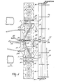
- the hollow frame portion 1 takes the form of an assembly of plates that includes a lower substantially channel-shaped plate having horizontal flanges to which an upper planar and substantially horizontally disposed cover plate is firmly but releas ably secured by a plurality of substantially regularly spaced apart and substantially vertically disposed bolts 2.
- each shaft 3 is vertically or substantially verticallydisposed.
- each shaft 3 projects downwardly from beneath the bottom of the hollow frame portion 1 and there has the hub of a corresponding rotary soil working member 4 firmly but releasably secured to it in such a way that each member 4 cannot move either rotatably or axially relative to the shaft 3 concerned,
- Each rotary soil working member 4 comprises a substantially horizontally disposed carrier 5 at the opposite ends of which are rigidly or integrally mounted two sleeve-like holders in which upper fastening portions of rigid cultivating members in the form of tines 6 are firmly but releasably secured.
- Each shaft 3 is provided, inside the hollow frame portion 1, with a corresponding straight-toothed or spur-toothed pinion 7 , the sizes of the twelve.(in this embodiment) pinions 7 being such that, as diagrammatically illustrated in Figure 1 of the drawings, the teeth of each pinion 7 are in driven and/or driving and driven mesh with those of the or each immediately neighbouring pinion in the single row thereof that is contained within the hollow frame portion 1. It will be seen that, with this arrangement, each pinion 7, together with the corresponding shaft 3 and rotary soil member 4, will revolve, during the operation of the implement, in a direction which is opposite to the direction of rotation of the or each immediately neighbouring similar assembly, small arrows in Figure 1 of the drawings indicating the directions of operative rotation.
- the opposite ends of the hollow frame portion 1 are closed by simple upright plates 4 0 ( Figure 2) of inverted trapeziform shape and, at two locations which are substantially one quarter of the distance from one end of the frame portion 1 towards the opposite end thereof, two substantially horizontally displaced plates 8 are mounted on top of the cover plate of the hollow frame portion 1, the two plates 8 being secured to the hollow frame portion 1 by appropriately positioned ones of the bolts 2 that secure the cover plate of the frame portion 1 to the underlying substantially channel-shaped part thereof.
- the two plates 8 are located midway between the shafts 3 that correspond to the third and fourth rotary soil working members 4 along the single row thereof counting from corresponding ends of that row.
- Each substantially horizontal plate 8 is provided, adjacent to the opposite edges thereof that extend parallel or substantially parallel to the direction A,with inner and outer (with respect to the centre of the frame portion 1) upright supports 9 and 10 that are substantially vertically parallel to one another and to the direction A and that extend throughout most, but not all, of the lengths of the hollow frame portion 1 as measured in the direction A. It will be seen from the drawings that, whilst the upper and lower edges of the two inner supports 9 are substantial l y horizontally parallel to one another, the upper edge of each outer support 10 is downwardly and forwardly inclined from rear to front with respect to the direction A.
- a strong horizontal pivot pin 11 interconnects the leading ends of the two-ûnner and outer upright supports 9 and 10 of each pair and extends substantially parallel to the transverse length of the horizontal frame portion 1 at a location above and towards the front of that frame portion 1 with respect to the direction A.
- Each of the two substantially coaxial pivot pins 11 is surrounded, between the corresponding pair of supports 9 and 10, by a horizontal sleeve 12 to which is secured the leading end of a rearwardly extending arm 13 which is in the form of a hollow beam of rectangular, and preferably square, cross section, said beam thus being of a construction that is resistant to torsional deformation.
- the rearmost ends of the two arms 13, which are behind the hollow frame portion 1 with respect to the direction A, are coupled to a carrier 15 of hollow formation and square cross section (see Figure 2) by means which includes upper and lower pairs of parallel strengthening plates14.As can be seen in the drawings , the two upper and lower strengthening plates 14 of each pair are located at the inner and relatively .facing sides of the two arms 13.
- the formation of the carrier 15 is such that said carrier has a strong resistance to torsional deformation, it being possible for it to have a rectangular, rather than strictly square, cross section, if preferred.
- the carrier 15 has.substantially the same length in a horizontal direction that is perpendicular to the direc-- tion A as does the hollow frame portion 1 and its opposite ends substantially register in the direction A, with the opposite ends of the frame portion.
- the free ends of the carrier 15 carry downwardly and rearwardly, with respect to the direction A, support .
- plates 16 ( Figures 1 and 2), each support plate 16 being substantially rectangular as seen in side elevation (Fig. 2)
- a ground roller 18 is mounted in a freely rotatable manner between substantially horizontal bearings carried at the rearmost and lowermost ends of the two support plates 16, stub shafts 17 at the opposite ends of the roller 18 being arranged to co-operate rotatably with said bearings.
- the ground roller 18 comprises a central axially extending shaft-to which a plurality such as seven, of circular support plates 20 are secured at regularly spaced part intervals which are such that one of said support plates 20 is located close to each opposite end of the roller 18.
- Each circular support plate 20 is formed, close to its edge, with a plurality such as ten, of regularly spaced apart holes through which elongate elements 19 of tubular or rod formation are entered in such a way as, preferably, to extend helically around the axis of rotation of the ground roller 18.
- the elongate elements 19 are releasable from the roller 18 and the maximum possible number, or a reduced number, thereof may be employed having regard to the nature and condition of the soil that is to be dealt with by the implement.
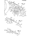
- Brackets that are secured to the top and front of the hollow frame portion 1, with respect to the direction A, secure a coupling member or trestle 21 to that frame portion 1 at a location midway between the opposite lateral sides or ends thereof, said coupling member or trestle 21 being of generally triangular configuration as seen in front or rear elevation.
- Tie beams 22 interconnect plates at the apex of the coupling member or trestle 21 and the two inner upright supports 9.
- the plates at the apex of the coupling member or trestle 21 include apertured lugs 27 arranged to co-operate pivotally with the upper lifting link of a three- point lifting device or hitch carried by an agricultural tractor or other operating vehicle of the implement.
- Lower portions of the coupling member or trestle 21 carry forwardly projecting lugs 27A to which the two lower lifting links of the same three-point lifting device or hitch can be connected in the generally known manner that is illustrated in outline in Figures 1 and 2 of the drawings employing substantially horizontally aligned pivot pins.
- Two horizontally spaced apart lugs 23 project substantially vertically upwards in parallel relationship with one another at a location midway along the transverse length of the upper surface of the beam which affords the carrier 15.
- Substantially horizontally aligned trunnion pins 24 turnably mount an adjustment mechanism 25 between the upper ends of the two lugs 23.
- the adjusting mechanism 25 is of a basically known kind which incorporates a screw-threaded rod which can be rotated in a matchingly screw-threaded part of a cylinder to increase, or decrease, the effective lengths of the mechanism 25, as may be regyired.
- the screw-threaded rod of the mechanism 25 projects from both opposite axial ends of the cylinder and is provided, at those ends, with corresponding upper and lower crank handles 28 and 29.
- An upper non- threaded portion of the screw-threaded rod passes between the lugs 27 at the top of the coupling member or trestle 21, a block being arranged around said portion of the rod at this point by way of a plain internal bore through which the rod is entered.
- the block is turnably connected to the two lugs 27 by a pair of horizontally aligned trunnion pins 26 and means are arranged so that the rod of the adjustment mechanism 25 can rotate freely in the block but cannot move axially relative thereto to any significant extent.
- the rod of the mechanism 25 can be rotated from either end by adjusting the upper crank handle 28 or the lower crank handle 29, the upper crank handle 28 being adjacent to the upper coupling point of the coupling member or trestle 21 and almost always being accessible from the driving seat of an agricultural tractor that is used to move and operate the implement without the driver of that tractor actually having to leave his/her seat.
- the lower crank - handle 29 is disposed substantially vertically above the ground roller 18 and can conveniently be manipulated by an operator standing on the ground immediately to the rear of the centre of the implement. It will be apparent that rotating the rod of the adjustment mechanism 25 in ai appropriate direction will either increase or decrease the distance between the pair of trunnion pins 24 and the pair-of trunnion pins 26.
- This change in the effective length of the mechanism 25 can only be accomodated by turning the arms 13, the carrier 15 and the roller 18 upwardly or downwardly about the substantially horizonatally aligned pivot pins 11. If the roller 18 is moved upwardly relative to the frame portion 1 and rotary soil working members 4, then the tines 6 of those members 4 will be able to penetrate more deeply into the ground during the operation of the implement and, conversely, if the roller 18 is lowered relative to the frame portion 1 and soil working members 4, the maximum depth of penetration of the tines 6 into the soil which is possible will be reduced.
- roller 18 is shown turned downwardly about the aligned pivot pins 11 to the maximum possible extent in which position of adjustment the lower faces of the arms 13 are in contact with the upper surfaces of the plates 8 on the hollow frame portion 1.
- One of the centre pair of rotary shafts 3 in the single row of those shafts is extended upwardly through the cover plate of the hollow frame portion 1 into a gear box 30 that is mounted on top of the hollow frame portion 1.
- a shaft and bevel pinion transmission within the gear box 30 places the upward extension of said shaft 3 in driven connection with a horizontally disposed rotary input shaft 32 of the gear box 30 that projects forwardly from the front of the gear box 30 in a horizontal direction that is parallel or substantially parallel to the direction A.
- the rotary input shaft 32 and an underlying parallel shaft that is not visible in the drawings have rearmost ends which project into a change-speedgear 31 that is mounted at the back of the gear box 3u with respect to the direction A.
- the ends of these two shafts are splined and co-operate with the matching internally splined hubs of pairs of toothed pinions of different sizes.
- the transmission ratio between the two shafts in the gear box 30, and thus the speed at which the soil working members 4 will be rotated in response to a substantially fixed speed of driving rotation that is applied to the leading end of the shaft 32, when the implement is in operation, will depend upon the particular pair of toothed pinions which is mounted on the splined ends of the two shafts that are accessible in the change-speed gear 31 and on the arrangement of those two pinions that is employed, it being noted that the two pinions of any particular pair are interchangeable on the shaft ends.
- a telescopic transmission shaft 33 which is of a construction that is known per se having universal joints at its opposite ends.
- the leading end of the telescopic transmission shaft 3 3 is, of course, connected to the rear power take-off shaft of the agricultural tractor or other vehicle which moves and operates the implement.
- each rotary soil working member 4 works a corresponding strip of soil that extends in the direction A and, since the distance between the tines 6 of each member 4 is a little greater than is tne distance between the longitudinal axes (axes of rotation) of immediately neighbouring shaft 3, said strips of soil overlap one another to produce a single broad strip of worked soil which, in the case of the implement that is being described by way of example, will have a width of substantially, although not necessarily exactly, three metres.
- the arms 13 are very resistant to torsional deformation and extend forwardly over the top of the hollow frame portion 1 whilst fitting closely between the corresponding pairs of inner and outer upright supports 9 and 10. This arrangement enables any desired depth setting to be chosen and maintained in a stable manner without there being any significant tendency for one end of the roller 18 to be at a different level, relative to the frame portion 1, as compared with the opposite end thereof.
- Figure 4 of the drawings illustrates the provision, on an upper rear portion of each outer upright support 10, of a numbered dial 34. It will be appreciated that, when the arms 13 are adjusted upwardly or downwardly about the substantially horizontal axis designed by the aligned pivot pins 11, the tops of said arms 13 will move along the dials 34 thus acting as pointers which co-operate with those dials.
- the dials 34 are visible from the driving seat of the agricultural tractor or other moving and operating vehicle arid are useful in eabling a correct depth setting to be arrived at both quickly and easily. In particular, it is only necessary to make of note of the dial marking which corresponds to a particular depth setting to enable exactly that same depth setting to be reestablished after a cultivating operation has been discontinued overnight or for some other reason.
- Figure 5 of the drawings illustrates an alternative form of adjustment indicator which may be employed in place of the adjustment indicator which comprises the dials 34.
- the non-rotary cylinder of the adjustment mechanism 25 carries, towards its upper end, a dial strip 37 that projects towards the upper crank handle 28 and that carries a dial comprising a rectilinear scale along which is movable a pointer 38.
- the construction and arrangement of the pointer 38 is not shown in detail in Figure 5 but it may comprise a sleeve fixedly connected around the upper rod of the adjustment. It will be appreciated that, once again, the dial 37 and the co-operating pointer 38 can be seen from the driving seat of an agricultural tractor which moves and operates the implement.
- Figure 6 of the drawings illustrates an alternative form of the adjusting machanism in which the mechanism 25 that comprises co-operating screw threads is replaced by a double-acting hydraulic piston and cylinder assembly or ram 35 whose cylinder is turnably mounted between the lugs 23 by the trunnion pins 24 and whose piston rod has its tree end pivotally mounted between the lugs 27 by a substantially horizontal pin which defines an axis that is parallel or substantially parallel to the transverse length of the hollow frame portion 1.
- Flexible hydraulic ducts 36 connect the opposite ends of the cylinder of the ram 35 to the hydraulic system of the co-opertaing tractor or other vehicle by way of quickly releasable self-sealing couplings of known construction and it will be apparent that the effective length of the mechanism or ram 35 can be increased, or decreased, as desired, merely by supplying hydraulic pressure medium to an appropriate end of the cylinder of the mechanism 35 and then maintaining any chosen setting, as long as may be desired, by an appropriate manipulation of the controls forming part of the hydraulic system of the co-operating tractor or other vehicle.
- the two pivot pins 11 that define the substantially horizontal axis about which the arms 13 are upwardly and downwardly turnable relative to the frame portion 1 are located quite close to respective ones of the two horizontally spaced apart lower coupling points at which, in use, the lower lifting linksof the three-point lifting device or hitch of the tractor or other operating vehicle are releasably coupled to the frame portion 1.
- reaction forces are transferred between the coupling member or trestle 21 and a support 39 ' ( Figure 1) of the roller 18 without the frame portion 1 itself having to have a very high resistance to bending and/or torsional deformation.
- the support 39 comprises the arms 13, the strengthening plates 14 and the roller carrier 15.
- the described construction enables the implement to operate. in a very stable manner whilst being resistant to damage by forces to which it is subject directly, or via the operating tractor or other vehicle, as a result of soil undulations, stones, buried roots and the like.
Landscapes
- Life Sciences & Earth Sciences (AREA)
- Engineering & Computer Science (AREA)
- Mechanical Engineering (AREA)
- Soil Sciences (AREA)
- Environmental Sciences (AREA)
- Soil Working Implements (AREA)
- Agricultural Machines (AREA)
Applications Claiming Priority (2)
| Application Number | Priority Date | Filing Date | Title |
|---|---|---|---|
| NL8102623 | 1981-05-29 | ||
| NL8102623A NL8102623A (nl) | 1981-05-29 | 1981-05-29 | Grondbewerkingsmachine. |
Related Parent Applications (2)
| Application Number | Title | Priority Date | Filing Date |
|---|---|---|---|
| EP82200657.3 Division | 1982-05-28 | ||
| EP82200657A Division EP0066344B1 (de) | 1981-05-29 | 1982-05-28 | Bodenbearbeitungsgeräte |
Publications (2)
| Publication Number | Publication Date |
|---|---|
| EP0136734A2 true EP0136734A2 (de) | 1985-04-10 |
| EP0136734A3 EP0136734A3 (de) | 1987-01-28 |
Family
ID=19837586
Family Applications (3)
| Application Number | Title | Priority Date | Filing Date |
|---|---|---|---|
| EP19840201101 Expired EP0135952B1 (de) | 1981-05-29 | 1982-05-28 | Bodenbearbeitungsgeräte |
| EP82200657A Expired EP0066344B1 (de) | 1981-05-29 | 1982-05-28 | Bodenbearbeitungsgeräte |
| EP84201105A Withdrawn EP0136734A3 (de) | 1981-05-29 | 1982-05-28 | Bodenbearbeitungsgeräte |
Family Applications Before (2)
| Application Number | Title | Priority Date | Filing Date |
|---|---|---|---|
| EP19840201101 Expired EP0135952B1 (de) | 1981-05-29 | 1982-05-28 | Bodenbearbeitungsgeräte |
| EP82200657A Expired EP0066344B1 (de) | 1981-05-29 | 1982-05-28 | Bodenbearbeitungsgeräte |
Country Status (3)
| Country | Link |
|---|---|
| EP (3) | EP0135952B1 (de) |
| DE (1) | DE3265064D1 (de) |
| NL (1) | NL8102623A (de) |
Cited By (2)
| Publication number | Priority date | Publication date | Assignee | Title |
|---|---|---|---|---|
| EP0222440A1 (de) * | 1985-10-29 | 1987-05-20 | C. van der Lely N.V. | Bodenbearbeitungsgerät |
| US4984957A (en) * | 1988-08-08 | 1991-01-15 | Kubota, Ltd. | Work-implement adapter for front loader |
Families Citing this family (5)
| Publication number | Priority date | Publication date | Assignee | Title |
|---|---|---|---|---|
| NL190180C (nl) * | 1983-01-18 | 1993-12-01 | Lely Nv C Van Der | Grondbewerkingsmachine. |
| NL8301074A (nl) * | 1983-03-28 | 1984-10-16 | Lely Nv C Van Der | Grondbewerkingsmachine. |
| NL8303042A (nl) * | 1983-09-01 | 1985-04-01 | Lely Nv C Van Der | Grondbewerkingsmachine. |
| GB2153642B (en) * | 1984-02-13 | 1988-10-26 | Lely Nv C Van Der | Soil cultivating implements |
| NL8403460A (nl) * | 1984-11-13 | 1986-06-02 | Lely Nv C Van Der | Grondbewerkingsmachine. |
Family Cites Families (22)
| Publication number | Priority date | Publication date | Assignee | Title |
|---|---|---|---|---|
| DE356537C (de) * | 1918-06-16 | 1922-07-26 | Mannesmann Mulag Motoren Und L | Stell- und Aushebevorrichtung fuer Motortragpfluege |
| FR541378A (fr) * | 1921-09-21 | 1922-07-26 | Perfectionnements aux charrues | |
| FR546679A (fr) * | 1921-12-05 | 1922-11-21 | Fond Oise & Seine | Perfectionnements apportés dans l'établissement des charrues |
| DE377856C (de) * | 1922-08-18 | 1923-06-28 | Masch Und Werkzeugfabrik Karl | Feststellvorrichtung fuer den heb- und senkbaren Pflugrahmen bei Motorpfluegen u. dgl. |
| US1845178A (en) * | 1925-11-13 | 1932-02-16 | Deere & Co | Power-actuated lifting mechanism for implements |
| DE874521C (de) * | 1940-06-05 | 1953-06-11 | Heinrich Lanz Ag | Anzeigevorrichtung fuer eine heb- und senkbare Vorrichtung an Fahrzeugen, insbesondere Zugmaschinen |
| US2654339A (en) * | 1949-12-19 | 1953-10-06 | Sperling John | Indicator for working position of agricultural tools |
| US2704047A (en) * | 1953-03-05 | 1955-03-15 | Lushenko Gordon | Indicating mechanism for ram operated agricultural tool |
| AT283799B (de) * | 1955-02-11 | 1970-08-25 | Rau Ohg Maschf | Gerätekombination zur Bodenbearbeitung für den Anbau an das Dreipunktgestänge eines Schleppers |
| FR1228412A (fr) * | 1959-02-28 | 1960-08-29 | Machine multiple, tractée et portée, pour la préparation combinée des terrains de culture | |
| US3101794A (en) * | 1959-09-30 | 1963-08-27 | Int Harvester Co | Angular adjusting means for a land clearing implement |
| US3045355A (en) * | 1959-10-26 | 1962-07-24 | John W Woods | Plow depth indicator |
| CH428295A (de) * | 1965-07-15 | 1967-01-15 | Buehler Josef | Traktor mit Egge und Walze |
| US3459268A (en) * | 1965-10-13 | 1969-08-05 | Albert P Forster | Crawler tractor ground pulverizer attachment |
| DE1967103A1 (de) * | 1968-05-29 | 1977-06-16 | Lely Nv C Van Der | Bodenbearbeitungsmaschine |
| US3572763A (en) * | 1968-11-22 | 1971-03-30 | Allis Chalmers Mfg Co | Three-point hitch |
| NL7416758A (nl) * | 1974-12-23 | 1976-06-25 | Lely Nv C Van Der | Grondbewerkingsmachine. |
| NL7602084A (nl) * | 1976-03-01 | 1977-09-05 | Lely Nv C Van Der | Grondbewerkingsmachine. |
| DE2718824A1 (de) * | 1976-06-01 | 1978-11-02 | Krone Bernhard Gmbh Maschf | Bodenbearbeitungsmaschine |
| GB1543854A (en) * | 1976-09-15 | 1979-04-11 | Amazonen Werke Dreyer H | Ground cultivating machine |
| NL7612404A (nl) * | 1976-11-09 | 1978-05-11 | Lely Nv C Van Der | Grondbewerkingsmachine. |
| DE2852526A1 (de) * | 1978-12-05 | 1980-06-19 | Fritz Guettler | Zugpunkt-hoehenverstellvorrichtung zur verstellung der eggenfeld-hoehenanordnung gegenueber dem ihm zugeordneten, von ihm gezogenen und mit ihm in wirkverbindung stehenden bodenkruemler in landwirtschaftlichen bodenbearbeitungskombinationen |
-
1981
- 1981-05-29 NL NL8102623A patent/NL8102623A/nl active Search and Examination
-
1982
- 1982-05-28 EP EP19840201101 patent/EP0135952B1/de not_active Expired
- 1982-05-28 DE DE8282200657T patent/DE3265064D1/de not_active Expired
- 1982-05-28 EP EP82200657A patent/EP0066344B1/de not_active Expired
- 1982-05-28 EP EP84201105A patent/EP0136734A3/de not_active Withdrawn
Cited By (2)
| Publication number | Priority date | Publication date | Assignee | Title |
|---|---|---|---|---|
| EP0222440A1 (de) * | 1985-10-29 | 1987-05-20 | C. van der Lely N.V. | Bodenbearbeitungsgerät |
| US4984957A (en) * | 1988-08-08 | 1991-01-15 | Kubota, Ltd. | Work-implement adapter for front loader |
Also Published As
| Publication number | Publication date |
|---|---|
| DE3265064D1 (en) | 1985-09-05 |
| EP0136734A3 (de) | 1987-01-28 |
| EP0135952A3 (en) | 1986-12-30 |
| EP0066344A1 (de) | 1982-12-08 |
| EP0135952A2 (de) | 1985-04-03 |
| EP0066344B1 (de) | 1985-07-31 |
| NL8102623A (nl) | 1982-12-16 |
| EP0135952B1 (de) | 1989-10-18 |
Similar Documents
| Publication | Publication Date | Title |
|---|---|---|
| US3821989A (en) | Rotary harrows | |
| US3977476A (en) | Soil cultivating implements | |
| US4049061A (en) | Rotary harrows | |
| US4136743A (en) | Soil cultivating implement | |
| US4083411A (en) | Soil cultivating implements | |
| US4071089A (en) | Soil cultivating implements | |
| US4114695A (en) | Rotary harrow with pivotable coupling assembly | |
| EP0135952B1 (de) | Bodenbearbeitungsgeräte | |
| US4113027A (en) | Soil cultivating implements | |
| EP0059520B1 (de) | Bodenbearbeitungsgeräte | |
| US4074765A (en) | Soil cultivating implements | |
| US4363362A (en) | Multiple machine for row-cropping with vertically operating axes | |
| GB2147481A (en) | Soil cultivating implements | |
| US4415039A (en) | Soil cultivating implements | |
| US4109730A (en) | Soil tilling machines | |
| GB2137462A (en) | Soil cultivating implement | |
| GB2147482A (en) | Soil cultivating implements | |
| US4136741A (en) | Soil cultivating implement | |
| US4042040A (en) | Cultivators | |
| GB2145611A (en) | Soil cultivating implements | |
| GB2130862A (en) | Soil cultivating implements | |
| GB2133662A (en) | Soil cultivating implements | |
| US3430702A (en) | Tractor mounted rod weeder | |
| GB2116411A (en) | Soil cultivating implement | |
| GB1591940A (en) | Soil cultivating implements |
Legal Events
| Date | Code | Title | Description |
|---|---|---|---|
| PUAI | Public reference made under article 153(3) epc to a published international application that has entered the european phase |
Free format text: ORIGINAL CODE: 0009012 |
|
| AC | Divisional application: reference to earlier application |
Ref document number: 66344 Country of ref document: EP |
|
| AK | Designated contracting states |
Designated state(s): CH DE FR GB IT LI |
|
| PUAL | Search report despatched |
Free format text: ORIGINAL CODE: 0009013 |
|
| AK | Designated contracting states |
Kind code of ref document: A3 Designated state(s): CH DE FR GB IT LI |
|
| 17P | Request for examination filed |
Effective date: 19870718 |
|
| 17Q | First examination report despatched |
Effective date: 19880928 |
|
| STAA | Information on the status of an ep patent application or granted ep patent |
Free format text: STATUS: THE APPLICATION IS DEEMED TO BE WITHDRAWN |
|
| 18D | Application deemed to be withdrawn |
Effective date: 19890411 |
|
| RIN1 | Information on inventor provided before grant (corrected) |
Inventor name: VAN DER LELY, CORNELIS |