EP0136628B1 - Appareil pour découpage hélicoidal des pommes de terre - Google Patents
Appareil pour découpage hélicoidal des pommes de terre Download PDFInfo
- Publication number
- EP0136628B1 EP0136628B1 EP84111247A EP84111247A EP0136628B1 EP 0136628 B1 EP0136628 B1 EP 0136628B1 EP 84111247 A EP84111247 A EP 84111247A EP 84111247 A EP84111247 A EP 84111247A EP 0136628 B1 EP0136628 B1 EP 0136628B1
- Authority
- EP
- European Patent Office
- Prior art keywords
- article
- holder
- passage
- cutting
- articles
- Prior art date
- Legal status (The legal status is an assumption and is not a legal conclusion. Google has not performed a legal analysis and makes no representation as to the accuracy of the status listed.)
- Expired
Links
- 0 CCC(CC1)CC1*=C Chemical compound CCC(CC1)CC1*=C 0.000 description 1
Images


Classifications
-
- B—PERFORMING OPERATIONS; TRANSPORTING
- B26—HAND CUTTING TOOLS; CUTTING; SEVERING
- B26D—CUTTING; DETAILS COMMON TO MACHINES FOR PERFORATING, PUNCHING, CUTTING-OUT, STAMPING-OUT OR SEVERING
- B26D7/00—Details of apparatus for cutting, cutting-out, stamping-out, punching, perforating, or severing by means other than cutting
- B26D7/06—Arrangements for feeding or delivering work of other than sheet, web, or filamentary form
-
- B—PERFORMING OPERATIONS; TRANSPORTING
- B26—HAND CUTTING TOOLS; CUTTING; SEVERING
- B26D—CUTTING; DETAILS COMMON TO MACHINES FOR PERFORATING, PUNCHING, CUTTING-OUT, STAMPING-OUT OR SEVERING
- B26D3/00—Cutting work characterised by the nature of the cut made; Apparatus therefor
- B26D3/10—Making cuts of other than simple rectilinear form
- B26D3/11—Making cuts of other than simple rectilinear form to obtain pieces of spiral or helical form
Definitions
- the present invention relates to an apparatus for cutting particles into helical strips according to the generic clause of claim 1.
- Raw potatoes and other vegetables have in the past been cut into pieces for cooking or freezing in a variety of ways using various apparatus.
- One method of cutting potatoes for making a french fried potato strip involves a fixed blade cutter against which a potato is rotated to cut it into a plurality of helical strips.
- This mechanism includes a cutting plate on which is mounted a pivot pin for engaging one end of a potato. The other end of the potato is engaged by a toothed drive disk which is mounted opposite the plate on a crank driven shaft.
- a set of slitting knives protrude from the surface of the cutting plate and a cutting knife is mounted to the cutting plate adjacent the pivot pin. The blade of this knife extends radially from the pivot pin in a plane parallel to the surface of the cutting plate.
- this device produces helically-cut potato strips, it suffers from several problems.
- the toothed drive disk further results in waste since the potato cannot be cut into helical strips from end to end without interference between the teeth of the drive disk and the cutting knives.
- the speed of operation of this device is further limited by the time required to load a potato into axial alignment with the pivot pin and drive disk and by the limitations on the rotational speed of the potato.
- a potato cutter having a barrel designed to contain and push a potato through a screen-cutter as the barrel is telescopically extended down over the cutter support.
- the barrel mounts several potato centering springs that are shifted out of contact with the potato after commencement of the cutting operation. These springs are confined to the inner surface of the barrel by the upper edge and the outer periphery of the support as the barrel is shifted downwards. Consequently, the fingers cannot function to control and hold the potato against rotatory fences imparted to the potato by a rotary cutter.
- US-A-2 826 229 discloses a rotatory potato cutter having a potato holder, a rotary cutting blade and a feeding plunger which is hand cranked downwards to push a potato into the cutting plate.
- Potato positioning is provided only by a pin protruding from the axis of the cutting plate. Consequently, only the downward bearing force of the plunger can secure the potato against rotation. This, combined with a knurled bottom surface of the plunger head will result in an uncut potato-end or but which must be removed by hand from the apparatus before a new potato is inserted for cutting. Such an apparatus cannot function as an automatic high-volume cutter.
- the object of the present invention is to provide an apparatus for rapidly cutting a potato into a plurality of helical strips without wastage of significant portions thereof.
- the apparatus uses a tubular potato holder which includes a plurality of fingers mounted to bear inwardly against the potato. The inner surfaces of these fingers are blunt to prevent cutting of the potato. In addition to their function of holding the potato, these fingers also center the potato as it is inserted into the holder.
- the potato is forced into engagement with a cutting head by means of a plunger.
- the sides of the plunger are deeply grooved at locations corresponding to each of the fingers so that the plunger may be extended through the cut without interfering with the holding and centering action of the fingers.
- the plunger is designed to be extended into the cup down to the rotating cutting head. Concentric grooves are provided in the end of the plunger to accommodate upstanding slitting knives which extend upwards above the level of the transverse blade. Preferred embodiments of the invention are disclosed in the dependent claims.
- the cutter head is kept free from excessive debris by -flowing water upwardly along its sides and over its surface. This water washes through the aperture in the cutting head beneath the transverse blade.
- the cutting head is mounted on a rotatably driven tube.
- This tube serves not only to conduct the rinsing water away from the cutting head but also to conduct the helically cut potato strips to a conveyor or bin. At high rotational speeds of the cutting head, however, the helically strips of potato may be held against the walls of the drive cylinder by centrifugal force.
- a sleeve is mounted in the tube to provide a non-rotating chute through which the water and potato strips are conducted away from the cutting head.
- the base of the drive tube is surrounded by a splash shield which contains any water that may leak outward past the top of the sleeve.
- the feeding and cutting of the potatoes may be automated as a result of the aforementioned configuration of the cutting mechanism.
- one or more cutting mechanisms are mounted on a table.
- An indexed table is provided with a plurality of cups for receiving potatoes. The bottom of these cups are open and positioned above a support plate.
- An indexing mechanism is provided to rotate the indexed table in predeter- minal increments. When one of the cups is indexed into position above the potato holder and cutter head, it drops through a hole in the support plate and into the holder. A plunger mechanism is then energized to force the potato downward against the cutting head.
- the plunger withdraws to a position above the cup, the indexing mechanism is actuated, and the next cup is moved into position to deliver a potato for cutting.
- Workers may be positioned about the periphery of the machine to manually insert potatoes into the cups in the indexed table. Potatoes may be supplied to these workers by means of a conveyor ring around the machine which continuously circulates the potatoes until they are picked up for loading. This conveyor may be supplied with potatoes by a vibrating conveyor or other known conveyor mechanism.
- potatoes may be supplied to the cups by means of an automatic feed mechanism.
- This feed mechanism may comprise an annular conveyor which circulates about the machine at a level above the cups.
- An infeed conveyor feeds potatoes to the annular conveyor and is controlled in response to a sensor to maintain an adequate supply of potatoes on the annular conveyor.
- Diverter gates are positioned at various locations about the annular conveyor to divert potatoes from the annular conveyor to feed hoppers.
- Potatoes are fed from the hopper to a vibrating chute which aligns the potatoes for cutting and transports them past an indexing mechanism which insures that no more than a single potato is loaded into any cup.
- a curved gravity biased plate engages potatoes released by the indexing mechanism to guide them to the cup and prevent them from tumbling as they are guided into the cup.
- Potatoes may be swept onto the annular conveyor from a belt conveyor and through a door by a diverter gate which is movable between a retracted position, an extended position and an intermediate position in response to signals from two sensor pairs which monitor the presence of potatoes on the annular conveyor.
- the apparatus is preferably controlled by an automatic sensing and control mechanism which automatically senses the position of various of the elements of the apparatus and of the sequences the operation thereof in response to this sensing.
- the present invention provides an apparatus for rapidly and automatically cutting vegetables such as potatoes into elongated helical strips.
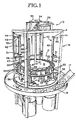
- this mechanism includes a frame 11 to which is mounted a rotatable feed mechanism 12, which is driven by an indexing system 13.
- a plunger system 14 and cutting system 16 are positioned about the periphery of the device.
- a vibrating conveyor mechanism 17 transports potatoes to an annular supply tray 18 which is rotatably mounted to the frame 11.
- the feed mechanism 12 includes a feed table 19 mounted on a rotatable vertical shaft 21.
- the table 19 is of generally circular configuration and includes a plurality of open-bottomed feed cups 22 mounted in apertures about its periphery. The open lower ends of the cups 22 are positioned immediately above an annular support plate 23 which is mounted to the frame 11 and supported above the surface of the table 24 by a plurality of support legs 26.
- a strip of low friction plastic material 27 is positioned beneath the cups 22 and mounted to the support plate 23 by means of a plurality of countersunk screws 28. Apertures are provided in the support plate 23 and plastic material 27 at positions such that potatoes can be loaded into the cutting system 16.
- the indexing mechanism 13 is operated by means of a pneumatic drive cylinder 29 and pneumatic locking cylinder 31.
- One end of the drive cylinder 29 is mounted to the frame 11 and the other is attached to the free end of a ratchet arm 32.
- the other end of the ratchet arm 32 is pivotably mounted to the shaft 21.
- a pawl 33 is pivotably mounted to the arm 32 adjacent the attachment point of the drive cylinder 29 and is spring biased into engagement with a ratchet wheel 36 which is, in turn, mounted on the shaft 21.
- a pair of limit switches 34, 35 are positioned, respectively, to close when the cylinder 29 is in its fully retracted and extended positions.
- Extension of the drive cylinder 29 thus results in rotation of the arm 32, pawl 33, ratchet wheel 36 and shaft 21. Since the feed table 24 is also- attached to the shaft 21, operation of the drive cylinder results in rotation of the table 24: .
- the length of the arm 32 and stroke of the cylinder 29 are chosen such that operation of the cylinder further results in sufficient movement of the table to position the next set of cups 22 above the apertures 30 in the support plate 23.
- the lock cylinder 31 actuates a locking mechanism 37 which prevents rotation of the cups 22 past the desired location.
- this lock mechanism 37 comprises a latch 38 which is mounted to the frame 11 and biased into engagement with the teeth 39 formed in the edge of the feed table 19 by a spring 41.
- the teeth 39 and latch 38 are configured to restrict rotation of the table 19 such that each feed cup 22 may be locked into position above the cutting system 16 in turn.
- Actuation of the lock cylinder 31 retracts the latch 38 and frees the feed table 19 to rotate.
- the index table may also, of course, be driven by an electric motor and the position of the table sensed by cam actuated switches as is known in the art.
- the plunger mechanism 14 comprises four identical plunger units 42.
- Each plunger unit 42 includes a double acting pneumatic cylinder 43 mounted to the frame 11 by upper and lower brackets 44, 46.
- the plunger head 47 is mounted on the shaft of the pneumatic cylinder 43.
- a rod 48 is mounted to the plunger head 47 and is slideably supported by the lower bracket 46 for vertical movement with the plunger head 47.
- Upper and lower limit switches 49, 51 are mounted on the upper and lower brackets 44, 46 in position for actuation by a tab 52 mounted on the free end of the rod 48, respectively, when the pneumatic cylinder is fully retracted or extended.
- the plunger head 47 is formed with deep grooves 53 extending longitudinally along it sides.
- concentric circular grooves 54 are formed into the lower surface of the plunger head 47. These grooves 53, 54 cooperate with elements of the cutting mechanism 16 as described below to provide complete and accurate cutting of potatoes or other vegetable.
- the cutting mechanism 16 comprises four identical cutting units 56. As best shown in Figs. 1-3, these cutting units 56 include a holder 57 for receiving and aligning potatoes for cutting. The holder 57 also secures the potatoes against rotation during the cutting process.
- the cutting units 56 include a rotatable cutter mechanism 58, a support 59 for rotatably mounting the cutter mechanism to the table 24, and a drive unit 61 for rotatably driving the cutter mechanism 58.
- the holder 57 includes a tubular body 62 mounted on a base plate 71 for receiving potatoes.
- a plurality of fingers 63 are hinged to the body 62 adjacent its upper lip and extend into the body 62 through corresponding slots 64.
- the inner surface 66 of each finger 63 is blunt to prevent cutting of the potatoes held in the body 62.
- a pin 68 is pivotably connected to each of the fingers 63 and mounts a spring for independently biasing the corresponding finger 63 into the interior of the tubular body 62.
- the outer end of the springs 67 bear against a ring 69 which is not mounted on the base plate 71 but rather is free to float as the fingers 63 move upon positioning of a potato in the holder 57. This allows the holder 57 to accommodate and align even highly irregular potatoes concentrically with the tubular body 62.
- the pins 67 extend through slots 72 in the ring 69 and include heads which bear against the outer surface of the ring 69 to limit inward travel of the fingers 63.
- a pair of nozzles 65 are mounted on the base plate 71 for supplying rinse water to the cutting head 58. Some of the rinse water supplied to the cutting head 58 may be impelled upward into the tubular body 62 of the holder 57 and exit through the slots 64.
- the holder may alternatively be constructed to remedy this problem.
- the water can be contained and prevented from flowing out onto the table 24 by mounting the ring 69 in a groove 70 in the base plate 71. Any water which accumulates within the confines of the ring 69 is drained away through one of the drain holes 75 in the base plate 71.
- the cutter mechanism 58 includes a blade assembly 74 and a flanged blade mount 76.
- the blade assembly 74 is generally disk shaped and includes a raised transverse blade 77 the edge of which extends radially from the center of the assembly 74.
- the transverse blade 77 is supported above the surface of the assembly 74 by a shoulder 75 on the opposite side of the center of the assembly 74.
- a plurality of upstanding slitting knives 78 extend upwardly from the surface of the blade assembly 74 and are removably attached thereto for example by soldering. The slitting knives extend upward from the surface of the assembly 74 to a position approximately 1/16 of an inch above the upper surface of the transverse blade 77.
- a center pin 79 is attached to the transverse blade 77 at the center of the blade assembly 74.
- the pin 79 does not extend below the lower surface of the transverse blade 77 nor do any obstructions depend from the lower surface of the blade assembly. This minimizes damage and breakage of the spiral strips of potatoes as they are cut and eliminates crushing of any portion of the potato against the surface of the blade assembly 74.
- the piercing action of pin 79 adjacent the edge of blade 77 produces an inner helical strip in lieu of a core.
- this blade assembly 74 produces the complete helical cutting of the potato, the innermost helical strip cut by the blade assembly 74 has only the internal radius produced by piercing of the potato by the pin 79. As such, this helical strip is extremely tightly coiled and to some extent is subject to breakage.
- a blade assembly 103 which includes a cutting tube 104 at its center in place of the pin 79 of the blade assembly 74 illustrated in Figs. 7 and 8.
- the upper end 106 of this tube is cut off at a 45 degree angle and is sharpened about its periphery so that it not only penetrates the potato but actually cuts a cylindrical core from the center of the potato.
- the cutting tube 104 is attached to the mounting plate 107 about most of its periphery but is not mounted to the transverse blade.
- the demountable transverse blade 108 is attached to the mounting plate 107.
- the corner 109 of this blade which abutts the cutting tube 104 is notched to conform to the periphery of the tube 104.
- the tube 104 can extend below the level of the horizontal knife without causing breakage of the innermost helical strip cut by the blade assembly 103, since this strip has a radius approximately equal to the radius of the cutting tube 104.
- Breakage of the helical strips can also be reduced by selection of the proper shape for the slitting knives 111.
- These knives 111 extend vertically from the blade assembly 74 and travel in a circular path as the blade assembly is rotated. It has been found that bending the knives 111 such that the radius of curvature of each knife 14 is approximately equal to the radius of the circular path traveled by such knife 111 advantageously reducing the tendency of the helical strips of potato to break during cutting and handling.
- the cutter drive assembly 61 includes a drive tube 86 which is rotatably supported in the cutter support housing 59 by upper and lower ball bearings 87.
- the upper end of the drive tube is threaded to receive the cutter assembly 58 and a seal 88 is positioned between the support housing 59 and drive tube 86 to seal out water from the nozzles 65.
- a pulley is mounted adjacent the lower end of the drive tube 86 and is driven by an electric motor 89 by means of a toothed belt 91.
- the cutter housing 59 and holder 57 are both mounted to the table 24 and are maintained in alignment with an aperture 92 therein by bolts 93 which extend through the base plate 71 of the holder 57 to engage the housing 59.
- a spray shield 94 is mounted totheframe 11 and encircles the lower end of the drive tube 86.
- a tubular chute 96 is mounted to the spray shield and extends upwardly into the drive tube 86 to a position just beneath the cutter assembly 58. This chute 96 conducts the strips of helically-cut potato strips and rinse water away from the cutter assembly 58 and prevents contact between the helically-cut potato strips and the rotating drive tube which otherwise could result in the strips being held against the walls of the tube by centrifugal force. Any water which leaks between the drive tube 86 and cute 96 drains to the bottom of the drive tube 86 and is caught by the spray shield 94 and drains out through the holes 97 in the bottom of the shield 94.
- the annular conveyor 18 surrounds the frame 11.
- a flanged track 98 is attached to the bottom of the conveyor 18 to receive the support wheels 99 which are rotatably mounted to the frame 11.
- a drive chain 100 is also attached to the bottom of the conveyor 18 along a circular path.
- a conveyor drive motor 101 drives a sprocket 102 which is positioned to engage the chain 100 and rotate the conveyor 18.
- Fig. 1 is shown as including onlyfour plunger units 42 and cutting units 56, additional plunging units and cutting units 42, 56 may be spaced about the apparatus. Of course, it is necessary that these units be spaced apart by at least one feed cup 22 so that potatoes can be fed to all cutting units 56.
- the loading of potatoes into the feed cups 22 may be automated. Such automation is particularly important when a large number of closely spaced plunger units 42 and cutting units 56 are mounted about the machine. As shown in Fig. 18 these cutting units may be spaced with only a single feed cup 22 between them.
- the automatic feed mechanism of the present invention includes an annular conveyor 112 which is similar in construction to the conveyor 18 shown in Fig. 1. As shown in Figs. 20-23, however, this conveyor 112 is mounted above the level of the feed cups 22 so that potatoes can be fed to the cups 22 along a downward path.
- a plurality of pneumatically operated diverter assemblies 113 are provided at positions spaced above the conveyor 112 for diverting potatoes from the conveyor 112 into the hoppers 114 associated with the diverter assemblies 113. As shown in Figs. 21 and 23, each hopper is asso- ' ciated with a pair of chutes 116 which feed the potatoes past an indexing system 116 which prevents more than one potato from entering a feed cup 22.
- the conveyor 112 is rotatably mounted to the frame 14 and driven in like manner to the conveyor 18 shown in Fig. 1. '
- the inner and outer walls 117, 118 bounding the annular conveyor 112, however, are fixed and do not rotate with the conveyor 112.
- Each pneumatic diverter assembly 113 is positioned adjacent a hopper and may be actuated to sweep potatoes off the conveyor 112 and into an associated hopper 114.
- the diverter assembly includes a diverter gate 119 which is pivotably mounted adjacent the wall 117 by means of a hinge 121.
- the diverter gate 119 is moved between a retracted position as illustrated in Fig. 21 and an advanced position as illustrated in Fig. 23 by means of a pneumatic actuator 122 and is formed so that, it conforms to the interior wall 117 which bounds the conveyor 112.
- the pneumatic actuator 122 like the remaining pneumatic actuators of the present apparatus are controlled by servo values which operate in response to electrical signals from the control system.
- an aperture is provided in the wall 118 opposite the diverter gate 119.
- a pair of doors 123, 124 are positioned to fill this aperture and are operated by a second pneumatic actuator 126.
- the first door 123 is pivotably mounted to the wall 118 by means of a vertically extending hinge 127, while the second door 124 is hinged along its top.
- a pin 129 extends upwardly from the first door and passes through an aperture in a block 131 which is mounted to the second door 124.
- the hopper 114 is positioned to receive potatoes diverted into it by the diverter gate 119 and conducts the potatoes downward to a pair of chutes 132 each of which is vibrated along its longitudinal axis by a vibrator 133. As illustrated in Figs. 19 and 21, each of these cutes is deeply troughed and becomes narrower with increasing distance from the hopper.
- the chute is inclined downwardly away from the hopper 114 to guide potatoes downward away from the hopper and towards the feed cups 22.
- the chutes 132 are made of sheet metal which has been formed with an irregular, textured surface such as by embossing the sheet metal with a pattern of recesses and prominences. Such a textured surface aids both the movement of the potatoes along the chute 132 and the alignment of the longitudinal axis of the potato with the longitudinal axis of the chute 132.
- the vibrating chute 132 terminates at the mouth of a descending, funnel shaped vertical chute 134 which ends just above the loading position of a feed cup.
- the chute 132 and the vertical chute 134 are not connected.
- a small gap is provided between the two chutes 132, 134 such that the vibrating chute 132 is free to vibrate while the funnel shaped chute remains stationary.
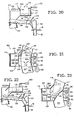
- An indexing mechanism 116 is positioned near the end of each chute 132. As shown in Fig. 18, this indexing mechanism 116 includes a tongue 136 which is hinged at one end to a support arm 137. The tongue is moved between a retracted position as illustrated in Fig. 20 and an advanced position as illustrated in Fig. 22 by means of a double acting pneumatic cylinder 138 which is pivotably connected at one end to the tongue 136 and at the other to the support arm 137. The tongue is bent such that the free end thereof extends generally parallel to the bottom of-the chute 132 when the pneumatic cylinder 138 moves it into its advanced position as illustrated in Fig. 22. The lower surface of this free end 139 is generally concave to conform to the upper sur- .face of a potato.
- a curved plate 141 is positioned to hang in the funnel shaped vertical chute 134. This plate is hinged to a support 142 so that its concave potato-engaging surface 143 may be pivoted away from the end of the vibrating chute 132.
- a counterbalance support arm 144 is connected to the top of the plate 141 and extends away from the end of the chute 132.
- a weight 146 is threaded onto the counterbalance arm 144 and can be positioned thereon to bias the concave surface 143 of the plate 142 toward the end of the chute 132.
- Potatoes are loaded onto the annular conveyor 112 by means of a belt type loading conveyor 115. This conveyor is controlled to load potatoes onto the annular conveyor 112 as needed to maintain an adequate supply of potatoes.
- the automatic loading mechanism is controlled in response to three sensors.
- a pair first sensors 147 is mounted above the annular conveyor 112 on a support 148. These sensor each comprises a light source 149 and a light detector 151.
- the light source 149 emits a beam of light downward onto the surface of the annular conveyor 112.
- the light detector 151 is mounted on the arm 148 in position to receive light reflected from the annular conveyor 112. When potatoes are not present on the conveyor, the beam emitted by the light source is reflected
- the second sensor 152 comprises a light source 153 and light detector 154 mounted on opposite sides of the two adjacent chutes 132.
- the light source 153 projects its beams through apertures 156 in the walls of the chutes 132 which beam is received by the light detector 154 unless blocked by potatoes in the chutes 132.
- the apertures 156 are of sufficient size that the oscillatory motion of the chutes 132 does not result in periodic interruption of the beam.
- the third sensor 157 is mounted at the end of the chute 132.
- the light source and detector 158, 159 that comprise this detector are mounted on opposite sides of the chute.
- the beam projected from the light source 158 to the detector 159 is positioned at an elevation above the bottom of the chute such that it will be blocked by a potato moving down the chute 132 into the funnel shaped vertical chute 134.
- the feed system 115 comprises a conveyer 161 which extends generally tangentially to the annular conveyor 112. Potatoes are swept from the conveyor 161 out the annular conveyor 112 by means of a sweep gate which is operated by a two stage pneumatic cylinder 163 such that it can be moved between a retracted, closed position, a position in which it extends completely across the conveyor 161 at an angle, and a position in which it extends only partially across the conveyor 161.
- potatoes are circulated past the several diverter assemblies 113 by the annular conveyor 112.
- the first sensor 147 monitors the supply of potatoes on the annular conveyor 112.
- the cylinder 163 is energized to fully open the sweep gate 162 to load potatoes onto the conveyor 112.
- the pneumatic cylinder 163 is energized only to open the sweep gate only part way.
- the feed system 115 is positioned downstream from the sensors 147, potatoes are added to the conveyor 112 at approximately the location where the deficiency was detected. Potatoes are loaded onto the conveyor 112 until the sensors 147 detects that an adequate supply of potatoes is present, after which the gate is closed.
- the feed system 115 is energized to supply potatoes only when approximately six inches or more of conveyor 112 has passed beneath the sensors 147 without detection of a potato.
- the several pneumatic diverter assemblies likewise operate only as needed to replenish the supply of potatoes in the hoppers 114.
- the diverter assembly 113 operates in response to the second sensor pair 152. So long as the light beam between the light source 153 and light detector 154 of this sensor 152 remain blocked by the presence of potatoes in the chutes 132, the diverter gate 119 remains in its retracted position against the inner wall 117.
- the pneumatic cylinder 121 is energized to advance the diverter gate 119 to the position illustrated in Figs. 22 and 23.
- the pneumatic actuator 126 is energized to open the doors 123, 124 and admit potatoes into the hopper 114.
- the sensors 152 detects the presence of potatoes in the chutes 132, the doors are closed and the diverter gate 119 and doors 123, 124 are retracted to the positions shown in Figs. 20 and 21.
- the chutes 132 are downwardly inclined and are reciprocated at a high rate by the vibrator 133.
- the potatoes thus move downward and inward toward the end of the chute.
- the chutes 132 narrow toward their end and the adjacent, interior walls of each pair of chutes 132 gradually becomes higher.
- the longitudinal axis of the potatoes becomes aligned with the longitudinal axis of the chutes as the potatoes move toward the indexing system 116.
- the indexing system 113 is controlled in response to the third sensor 157.
- the function of the index system is to ensure that only a single potato is deposited in each feed cup 22 and that potatoes are not permitted to enter the funnel shaped vertical chute 134 when the feed cups 22 are being moved into position above one of the cutting heads 56 as described above.
- potatoes are transported to the annular conveyor 18 by a vibrating conveyor 19. Workers are positioned about the periphery of the machine to take potatoes from the conveyor 18 and insert them into the cups 22 mounted on the feed table 19.
- the control circuit As illustrated in Fig. 9, when the power is turned on power flows to the control circuit through the fuse F1. The machine remains inactive until energized by the pressing of the start switch PB1. When this switch is pressed, power flows through the normally closed switch PB2 to the coil of the first relay CR1 causing the contacts CR1a to close and bypass the start switch PB2.
- the contacts CRSb also dose, providing power to the rest of the circuit.
- the pneumatic cylinders 43 When power is applied, the pneumatic cylinders 43 are in their retracted position and the upper limit switches 49 are therefore closed.
- the delay-on-operate time delay relay TDR1 is energized.
- the ratched drive cylinder 29 is retracted and the limit switch 34 is closed.
- the contact of this relay is normally closed and thus the energizing of this relay supplies power to the energizing line 103 of the delay-on-release time delay relay TDR2. Voltage is thus applied to the delay-on-operate relay TDR4 and the bypass relay CR2.
- TDR2 When TDR2 energizes, the contacts TDR2a open, releasing the delay-on-operate relay TDR4, the relay CR2 and the ratchet solenoid valve releases, retracting the cylinder and closing the limit switch 34.
- the time delay relay TDR2 then de-energizes, closing the contacts TDR2a.
- the delay-on-operate relay TDR4 is energized and the relay CR2 closes.
- the energizing of this relay CR2 bypasses the limit switch 34 maintaining current through the closed contacts TDR2a.
- the contacts TDR2b also close, energizing the delay-on-release time delay relay TDR3. This results in the closure of the contacts TDR3a, actuating the solenoid valve SOL2 which supplies air to the lock cylinder 31. This cylinder then retracts the latch 38 to free the feed table 19 to rotate.
- the time delay relay TDR4 then de-energizes opening the contacts TDR4a and TDR4b. This supplies current to the energized line 104 of the delay-on-release time delay relay TDR3. As a result, the contacts TDR3a close causing the solenoid -valve controlling the ratchet drive cylinder is energized causing the cylinder to extend. This results in rotation of the ratchet wheel 36 and feed table 19. As the drive cylinder extends, the time delay on TDR3 runs out and the contacts TDR3a open the solenoid valve SOL2 which controls the lock cylinder 31. The latch 38 then moves into contact with the edge of the feed table 19. The stroke of the ratchet cylinder. 29 continues until it is fully extended at which time the limit switch 35 closes.
- the downward stroke of the cylinders 43 forces the potatoes into contact with the rotating cutter assemblies 58.
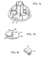
- the slitting knives 78 first cut a plurality of concentric grooves in the potatoes and the potato is then helically sliced by the transverse blade 77 as shown in Figs. 12 and 13. The cutting continues until the cylinder reaches full extension at which time the plunger head 47 has moved down to the level of the transverse blade 77.
- the slitting knives 78 which extend upward past the level of the transverse blade 77 are received in the concentric grooves 54 in the lower end of the plunger. As the plunger head moves downward through the holder, the vertical grooves 53 in the plunger head 47 receive the fingers.
- grooves 53 are of sufficient depth to avoid interference with the fingers, which must continue to hold the potato against rotation throughout the entire downward stroke of the cylinder 43. If the blade assembly of fig. 15 is used, of course, a cylindrical core is also cut from the potato as shown in Fig. 16.
- the operation of the device may also be advantageously monitored and controlled by a conventional programmable controller.
- a conventional programmable controller which may be used is the Texas Instrument 530 programmable controller which is provided by the industrial systems division of Texas Instruments, Inc. of Johnson City, Tennessee. This programmable controller may be interfaced in a known manner to the various switches, sensors and servo valves of the apparatus to control its function.
- the Texas Instruments, Inc., model 530 programmable controller is designed to control machines by stepping through its program and performing specific functions in response to various internal pulses which may have a duration, for example, of one complete program cycle.
- the computer may repeatedly bypass an instruction to energize the servo valve which controls a cylinder until conditions are satisfied in a preceding instruction and a pulse is sent on an internal control line to indicate establishment of the desired condition precedent to operation of the cylinder.
- the processor in the programmable controller may examine each instruction and the conditions precedent for its execution many times per second. This ensures that all machine functions are carried out on a timely basis and that it is not necessary, for example, to wait for the index table to complete its movement before the next function can be carried out. Setting up a machine control program to operate in this manner is well known in the art. For sake of clarity in explaining the program, the various functions and the conditions for their execution have been grouped and described in conventional flow chart form.
- the first step 164 is the initialization of the machine including the setting of timers for later use. Rotation of the index table is next initiated. In subsequent sweeps through the program, the programmable controller will turn off the drive to the index table 19 when it has completed its indexing as indicated by cam actuated limit switches (not shown). Once movement of the table is complete, the vibrator 133 is then turned on and the tongue 136 is retracted to allow the feeding of a potato to the feed cup 22. The programmable controller next executes a step 166 to determine whether the third sensor positioned at the end of the chute 132 has been unblocked.
- the programmable controller monitors the state of this third sensor 157 to determine when the light beam between the source and detector pair 158, 159 has been blocked and then unblocked indicating the passage of a potato through the sensor 157. Also after the motion of the index table has stopped, the cylinders 43 which operate the plunger 47 are energized to move downward. At this point 167, a timer is also started in order to set a maximum transit time for the stroke of the cylinder 43. If the timer expires before one or more of the plungers reach the bottom of their stroke, as indicated by closure of the lower limit switches 51, such plungers are retracted and disabled.
- the tongue 153 associated with such sensors is extended and disabled. If both indexing systems 112 which are supplied by the same hopper 114 are disabled, the diverter assembly 113 serving that hopper 114 is also disabled.
- the programmable controller checks for blockage of each of the second sensors 153.
- the diverter gate 119 is extended and the doors 123, 124 opened to admit potatoes into the hopper 114. After the sensor 152 has been blocked for a predetermined period of time, the diverter gate is retracted and a short time later the doors 123, 124 are closed.
- the programmable controller also checks the pair of first sensors for blockage by potatoes. In a subsequent step 171, if only one of the sensors is blocked, the sweep gate 162 is opened part way. If neither sensor is blocked by potatoes, however, the sweep gate will be fully opened. After the gate 162 has been opened, the programmable controller monitors the sensors and closes the sweep gate when an adequate supply of potatoes is detected by blockage of both sensors. The programmable controller then returns to continue execution of the program.
Landscapes
- Life Sciences & Earth Sciences (AREA)
- Forests & Forestry (AREA)
- Engineering & Computer Science (AREA)
- Mechanical Engineering (AREA)
- Apparatuses For Bulk Treatment Of Fruits And Vegetables And Apparatuses For Preparing Feeds (AREA)
- Preparation Of Fruits And Vegetables (AREA)
- Feeding Of Articles To Conveyors (AREA)
- Wire Processing (AREA)
Claims (19)
Priority Applications (1)
| Application Number | Priority Date | Filing Date | Title |
|---|---|---|---|
| AT84111247T ATE35392T1 (de) | 1983-09-20 | 1984-09-20 | Vorrichtung zum schraubenfoermigen schneiden von kartoffeln. |
Applications Claiming Priority (2)
| Application Number | Priority Date | Filing Date | Title |
|---|---|---|---|
| US53418283A | 1983-09-20 | 1983-09-20 | |
| US534182 | 1983-09-20 |
Publications (2)
| Publication Number | Publication Date |
|---|---|
| EP0136628A1 EP0136628A1 (fr) | 1985-04-10 |
| EP0136628B1 true EP0136628B1 (fr) | 1988-06-29 |
Family
ID=24129016
Family Applications (1)
| Application Number | Title | Priority Date | Filing Date |
|---|---|---|---|
| EP84111247A Expired EP0136628B1 (fr) | 1983-09-20 | 1984-09-20 | Appareil pour découpage hélicoidal des pommes de terre |
Country Status (7)
| Country | Link |
|---|---|
| EP (1) | EP0136628B1 (fr) |
| JP (1) | JPS60155398A (fr) |
| AT (1) | ATE35392T1 (fr) |
| AU (1) | AU576205B2 (fr) |
| CA (1) | CA1225910A (fr) |
| DE (2) | DE3472377D1 (fr) |
| IE (1) | IE55608B1 (fr) |
Cited By (1)
| Publication number | Priority date | Publication date | Assignee | Title |
|---|---|---|---|---|
| DE102015213139A1 (de) * | 2015-07-14 | 2017-01-19 | The Lorenz Bahlsen Snack-World Gmbh & Co Kg Germany | Verfahren und Vorrichtung zur Herstellung eines scheibenförmig aufgeschnittenen Lebensmittels |
Families Citing this family (13)
| Publication number | Priority date | Publication date | Assignee | Title |
|---|---|---|---|---|
| US4926726A (en) * | 1987-11-12 | 1990-05-22 | Lamb-Weston, Inc. | Food processing apparatus |
| US5201259A (en) * | 1987-11-12 | 1993-04-13 | Lamb-Weston, Inc. | Food processing apparatus |
| US5089286A (en) * | 1990-07-18 | 1992-02-18 | National Presto Industries, Inc. | Appliance for spirally slicing fruits and vegetables |
| US5138940A (en) * | 1990-07-18 | 1992-08-18 | National Presto Industries, Inc. | Appliance for spirally slicing fruits and vegetables |
| US5224409A (en) * | 1991-03-19 | 1993-07-06 | Ashlock Company | Apparatus for producing helical slices |
| AU660680B2 (en) * | 1991-04-09 | 1995-07-06 | Conagra Foods Packaged Foods Company, Inc. | Cutting assembly |
| US5385074A (en) * | 1993-02-23 | 1995-01-31 | Cavendish Farms Limited | Apparatus and method for cutting helically shaped potato pieces |
| GB2315991B (en) * | 1996-08-08 | 2001-01-10 | Winyard Engineering Ltd | Vegetable cutter |
| FR2800661A1 (fr) * | 1999-11-10 | 2001-05-11 | Gerard Tisserand | Spirale a pomme de terre |
| DE20004774U1 (de) * | 2000-03-15 | 2000-09-28 | Isele Theodor | Nahtlose Schnittscheibe für Gemüse-Kartoffel |
| FR2817499A1 (fr) * | 2000-12-04 | 2002-06-07 | Gerard Tisserand | Serpentin a pomme de terre |
| CN108177177B (zh) * | 2017-12-28 | 2020-07-24 | 嵊州市鉴亭新材料科技有限公司 | 一种土豆快速切片装置 |
| CN112571493B (zh) * | 2020-11-20 | 2022-06-24 | 恩施福硒康农业科技有限公司 | 一种制药用木瓜自动切块装置 |
Family Cites Families (8)
| Publication number | Priority date | Publication date | Assignee | Title |
|---|---|---|---|---|
| GB599039A (en) * | 1945-09-12 | 1948-03-03 | Harry Vernon Tooley | Improvements in or relating to slicing machines |
| US497675A (en) * | 1893-05-16 | Fruit or vegetable cutter | ||
| US1534078A (en) * | 1924-07-11 | 1925-04-21 | Potato Waffles Inc | Vegetable-slicing machine |
| GB333015A (en) * | 1929-06-27 | 1930-08-07 | William Forbes Wilson | Improvements relating to vegetable cutters |
| US2610664A (en) * | 1949-11-14 | 1952-09-16 | Wallace A Thompson | Potato cutter |
| US2826229A (en) * | 1955-06-27 | 1958-03-11 | Necula Joe | Potato cutting device |
| JPS5299269A (en) * | 1976-02-11 | 1977-08-19 | Shiyanboozu Jieimuzu | Vegetable cutting machine |
| US4372184A (en) * | 1981-02-25 | 1983-02-08 | J. R. Simplot Company | Cutting assembly |
-
1984
- 1984-09-18 CA CA000463524A patent/CA1225910A/fr not_active Expired
- 1984-09-19 IE IE2380/84A patent/IE55608B1/en not_active IP Right Cessation
- 1984-09-20 DE DE8484111247T patent/DE3472377D1/de not_active Expired
- 1984-09-20 AU AU33336/84A patent/AU576205B2/en not_active Expired
- 1984-09-20 AT AT84111247T patent/ATE35392T1/de active
- 1984-09-20 JP JP59197749A patent/JPS60155398A/ja active Pending
- 1984-09-20 EP EP84111247A patent/EP0136628B1/fr not_active Expired
- 1984-09-20 DE DE198484111247T patent/DE136628T1/de active Pending
Cited By (1)
| Publication number | Priority date | Publication date | Assignee | Title |
|---|---|---|---|---|
| DE102015213139A1 (de) * | 2015-07-14 | 2017-01-19 | The Lorenz Bahlsen Snack-World Gmbh & Co Kg Germany | Verfahren und Vorrichtung zur Herstellung eines scheibenförmig aufgeschnittenen Lebensmittels |
Also Published As
| Publication number | Publication date |
|---|---|
| AU3333684A (en) | 1985-03-28 |
| IE842380L (en) | 1985-03-20 |
| CA1225910A (fr) | 1987-08-25 |
| ATE35392T1 (de) | 1988-07-15 |
| JPS60155398A (ja) | 1985-08-15 |
| IE55608B1 (en) | 1990-11-21 |
| EP0136628A1 (fr) | 1985-04-10 |
| AU576205B2 (en) | 1988-08-18 |
| DE3472377D1 (en) | 1988-08-04 |
| DE136628T1 (de) | 1985-09-12 |
Similar Documents
| Publication | Publication Date | Title |
|---|---|---|
| US4644838A (en) | Apparatus for helical cutting of potatoes | |
| EP0136628B1 (fr) | Appareil pour découpage hélicoidal des pommes de terre | |
| JP3167028B2 (ja) | 切断アセンブリ | |
| AU638608B2 (en) | Measuring system for simply realizing high precision measuring of a wide range of work including viscous substances | |
| US3994117A (en) | Method and apparatus for filling containers | |
| KR102117164B1 (ko) | 식품 자동 슬라이서 | |
| EP0796566A2 (fr) | Appareil pour dénoyauter des pruneaux ou des dattes | |
| JPH08118288A (ja) | 2つ以上の食物の塊をスライスする装置及び方法 | |
| US4481875A (en) | Bulb peeling apparatus | |
| US3739471A (en) | Apparatus for automatically opening and emptying containers into a blending tank | |
| US4145990A (en) | Apparatus for applying grated cheese to pizza shells | |
| US4264634A (en) | Method for applying grated cheese to pizza shells | |
| NZ198261A (en) | Apparatus for portioning meat: bandsaw with horizontal cutting flight | |
| US3137330A (en) | Egg handling machinery | |
| KR102094387B1 (ko) | 케익커팅장치 및 이를 포함하는 케익 커팅 및 이송 시스템 | |
| US20050220956A1 (en) | Method and device for shaping foodstuffs and the like, and shaped product | |
| WO2004113172A1 (fr) | Machine d'emballage | |
| KR100719616B1 (ko) | 슬라이서 | |
| KR20030062250A (ko) | 식품 슬라이서 | |
| US3853620A (en) | Method for automatically opening and emptying containers into a blending tank | |
| CN115555101B (zh) | 一种用于蔬菜加工的破碎装置 | |
| US20240099495A1 (en) | Automated avocado processing system and related method | |
| JPH062005B2 (ja) | 茸切断装置 | |
| USRE28077E (en) | Automatic heat cutting machine | |
| JP2002145454A (ja) | 青果物選別における青果投入装置 |
Legal Events
| Date | Code | Title | Description |
|---|---|---|---|
| PUAI | Public reference made under article 153(3) epc to a published international application that has entered the european phase |
Free format text: ORIGINAL CODE: 0009012 |
|
| AK | Designated contracting states |
Designated state(s): AT BE CH DE FR GB IT LI NL SE |
|
| ITCL | It: translation for ep claims filed |
Representative=s name: DE DOMINICIS & PARTNERS |
|
| EL | Fr: translation of claims filed | ||
| TCAT | At: translation of patent claims filed | ||
| DET | De: translation of patent claims | ||
| 17P | Request for examination filed |
Effective date: 19850904 |
|
| 17Q | First examination report despatched |
Effective date: 19861001 |
|
| D17Q | First examination report despatched (deleted) | ||
| ITF | It: translation for a ep patent filed |
Owner name: DE DOMINICIS & MAYER S.R.L. |
|
| RAP3 | Party data changed (applicant data changed or rights of an application transferred) |
Owner name: UNIVERSAL FROZEN FOODS CO. |
|
| GRAA | (expected) grant |
Free format text: ORIGINAL CODE: 0009210 |
|
| AK | Designated contracting states |
Kind code of ref document: B1 Designated state(s): AT BE CH DE FR GB IT LI NL SE |
|
| REF | Corresponds to: |
Ref document number: 35392 Country of ref document: AT Date of ref document: 19880715 Kind code of ref document: T |
|
| REF | Corresponds to: |
Ref document number: 3472377 Country of ref document: DE Date of ref document: 19880804 |
|
| ET | Fr: translation filed | ||
| PLBE | No opposition filed within time limit |
Free format text: ORIGINAL CODE: 0009261 |
|
| STAA | Information on the status of an ep patent application or granted ep patent |
Free format text: STATUS: NO OPPOSITION FILED WITHIN TIME LIMIT |
|
| 26N | No opposition filed | ||
| PGFP | Annual fee paid to national office [announced via postgrant information from national office to epo] |
Ref country code: FR Payment date: 19910918 Year of fee payment: 8 |
|
| PGFP | Annual fee paid to national office [announced via postgrant information from national office to epo] |
Ref country code: NL Payment date: 19910930 Year of fee payment: 8 |
|
| PGFP | Annual fee paid to national office [announced via postgrant information from national office to epo] |
Ref country code: CH Payment date: 19911022 Year of fee payment: 8 |
|
| PGFP | Annual fee paid to national office [announced via postgrant information from national office to epo] |
Ref country code: AT Payment date: 19911126 Year of fee payment: 8 |
|
| PG25 | Lapsed in a contracting state [announced via postgrant information from national office to epo] |
Ref country code: AT Effective date: 19920920 |
|
| ITTA | It: last paid annual fee | ||
| PG25 | Lapsed in a contracting state [announced via postgrant information from national office to epo] |
Ref country code: LI Effective date: 19920930 Ref country code: CH Effective date: 19920930 |
|
| PG25 | Lapsed in a contracting state [announced via postgrant information from national office to epo] |
Ref country code: NL Effective date: 19930401 |
|
| NLV4 | Nl: lapsed or anulled due to non-payment of the annual fee | ||
| PG25 | Lapsed in a contracting state [announced via postgrant information from national office to epo] |
Ref country code: FR Effective date: 19930528 |
|
| REG | Reference to a national code |
Ref country code: CH Ref legal event code: PL |
|
| REG | Reference to a national code |
Ref country code: FR Ref legal event code: ST |
|
| NLXE | Nl: other communications concerning ep-patents (part 3 heading xe) |
Free format text: A REQUEST FOR RESTORATION TO THE PRIOR STATE HAS BEEN FILED ON 931231 |
|
| EAL | Se: european patent in force in sweden |
Ref document number: 84111247.7 |
|
| REG | Reference to a national code |
Ref country code: GB Ref legal event code: 732E |
|
| REG | Reference to a national code |
Ref country code: GB Ref legal event code: IF02 |
|
| PGFP | Annual fee paid to national office [announced via postgrant information from national office to epo] |
Ref country code: SE Payment date: 20030904 Year of fee payment: 20 |
|
| PGFP | Annual fee paid to national office [announced via postgrant information from national office to epo] |
Ref country code: GB Payment date: 20030917 Year of fee payment: 20 |
|
| PGFP | Annual fee paid to national office [announced via postgrant information from national office to epo] |
Ref country code: DE Payment date: 20031002 Year of fee payment: 20 |
|
| PGFP | Annual fee paid to national office [announced via postgrant information from national office to epo] |
Ref country code: BE Payment date: 20031203 Year of fee payment: 20 |
|
| PG25 | Lapsed in a contracting state [announced via postgrant information from national office to epo] |
Ref country code: GB Free format text: LAPSE BECAUSE OF EXPIRATION OF PROTECTION Effective date: 20040919 |
|
| BE20 | Be: patent expired |
Owner name: *UNIVERSAL FROZEN FOODS CO. Effective date: 20040920 |
|
| REG | Reference to a national code |
Ref country code: GB Ref legal event code: PE20 |
|
| EUG | Se: european patent has lapsed | ||
| REG | Reference to a national code |
Ref country code: SE Ref legal event code: EUG |