EP0136282B2 - Dispositif pour freiner des moteurs électriques - Google Patents
Dispositif pour freiner des moteurs électriques Download PDFInfo
- Publication number
- EP0136282B2 EP0136282B2 EP84890162A EP84890162A EP0136282B2 EP 0136282 B2 EP0136282 B2 EP 0136282B2 EP 84890162 A EP84890162 A EP 84890162A EP 84890162 A EP84890162 A EP 84890162A EP 0136282 B2 EP0136282 B2 EP 0136282B2
- Authority
- EP
- European Patent Office
- Prior art keywords
- brake body
- brake
- squirrel
- cage rotor
- projection
- Prior art date
- Legal status (The legal status is an assumption and is not a legal conclusion. Google has not performed a legal analysis and makes no representation as to the accuracy of the status listed.)
- Expired - Lifetime
Links
- 239000007779 soft material Substances 0.000 claims abstract 2
- 230000006835 compression Effects 0.000 claims description 7
- 238000007906 compression Methods 0.000 claims description 7
- 230000002093 peripheral effect Effects 0.000 claims 1
- 239000002184 metal Substances 0.000 description 5
- 239000004020 conductor Substances 0.000 description 3
- 238000009423 ventilation Methods 0.000 description 3
- 239000000696 magnetic material Substances 0.000 description 2
- 239000000463 material Substances 0.000 description 2
- 238000000034 method Methods 0.000 description 2
- 238000004026 adhesive bonding Methods 0.000 description 1
- 238000006073 displacement reaction Methods 0.000 description 1
- 230000002349 favourable effect Effects 0.000 description 1
- 238000005245 sintering Methods 0.000 description 1
- 210000002105 tongue Anatomy 0.000 description 1
- 238000004804 winding Methods 0.000 description 1
Images


Classifications
-
- F—MECHANICAL ENGINEERING; LIGHTING; HEATING; WEAPONS; BLASTING
- F16—ENGINEERING ELEMENTS AND UNITS; GENERAL MEASURES FOR PRODUCING AND MAINTAINING EFFECTIVE FUNCTIONING OF MACHINES OR INSTALLATIONS; THERMAL INSULATION IN GENERAL
- F16D—COUPLINGS FOR TRANSMITTING ROTATION; CLUTCHES; BRAKES
- F16D55/00—Brakes with substantially-radial braking surfaces pressed together in axial direction, e.g. disc brakes
- F16D55/02—Brakes with substantially-radial braking surfaces pressed together in axial direction, e.g. disc brakes with axially-movable discs or pads pressed against axially-located rotating members
-
- F—MECHANICAL ENGINEERING; LIGHTING; HEATING; WEAPONS; BLASTING
- F16—ENGINEERING ELEMENTS AND UNITS; GENERAL MEASURES FOR PRODUCING AND MAINTAINING EFFECTIVE FUNCTIONING OF MACHINES OR INSTALLATIONS; THERMAL INSULATION IN GENERAL
- F16D—COUPLINGS FOR TRANSMITTING ROTATION; CLUTCHES; BRAKES
- F16D59/00—Self-acting brakes, e.g. coming into operation at a predetermined speed
- F16D59/02—Self-acting brakes, e.g. coming into operation at a predetermined speed spring-loaded and adapted to be released by mechanical, fluid, or electromagnetic means
-
- H—ELECTRICITY
- H02—GENERATION; CONVERSION OR DISTRIBUTION OF ELECTRIC POWER
- H02K—DYNAMO-ELECTRIC MACHINES
- H02K7/00—Arrangements for handling mechanical energy structurally associated with dynamo-electric machines, e.g. structural association with mechanical driving motors or auxiliary dynamo-electric machines
- H02K7/10—Structural association with clutches, brakes, gears, pulleys or mechanical starters
- H02K7/102—Structural association with clutches, brakes, gears, pulleys or mechanical starters with friction brakes
- H02K7/1021—Magnetically influenced friction brakes
- H02K7/1026—Magnetically influenced friction brakes using stray fields
- H02K7/1028—Magnetically influenced friction brakes using stray fields axially attracting the brake armature in the frontal area of the magnetic core
-
- F—MECHANICAL ENGINEERING; LIGHTING; HEATING; WEAPONS; BLASTING
- F16—ENGINEERING ELEMENTS AND UNITS; GENERAL MEASURES FOR PRODUCING AND MAINTAINING EFFECTIVE FUNCTIONING OF MACHINES OR INSTALLATIONS; THERMAL INSULATION IN GENERAL
- F16D—COUPLINGS FOR TRANSMITTING ROTATION; CLUTCHES; BRAKES
- F16D2121/00—Type of actuator operation force
- F16D2121/18—Electric or magnetic
- F16D2121/20—Electric or magnetic using electromagnets
- F16D2121/22—Electric or magnetic using electromagnets for releasing a normally applied brake
-
- F—MECHANICAL ENGINEERING; LIGHTING; HEATING; WEAPONS; BLASTING
- F16—ENGINEERING ELEMENTS AND UNITS; GENERAL MEASURES FOR PRODUCING AND MAINTAINING EFFECTIVE FUNCTIONING OF MACHINES OR INSTALLATIONS; THERMAL INSULATION IN GENERAL
- F16D—COUPLINGS FOR TRANSMITTING ROTATION; CLUTCHES; BRAKES
- F16D2125/00—Components of actuators
- F16D2125/18—Mechanical mechanisms
- F16D2125/20—Mechanical mechanisms converting rotation to linear movement or vice versa
- F16D2125/34—Mechanical mechanisms converting rotation to linear movement or vice versa acting in the direction of the axis of rotation
- F16D2125/36—Helical cams, Ball-rotating ramps
-
- F—MECHANICAL ENGINEERING; LIGHTING; HEATING; WEAPONS; BLASTING
- F16—ENGINEERING ELEMENTS AND UNITS; GENERAL MEASURES FOR PRODUCING AND MAINTAINING EFFECTIVE FUNCTIONING OF MACHINES OR INSTALLATIONS; THERMAL INSULATION IN GENERAL
- F16D—COUPLINGS FOR TRANSMITTING ROTATION; CLUTCHES; BRAKES
- F16D2127/00—Auxiliary mechanisms
- F16D2127/08—Self-amplifying or de-amplifying mechanisms
- F16D2127/10—Self-amplifying or de-amplifying mechanisms having wedging elements
Definitions
- the invention relates to a device for braking electric motors with short-circuit rotors, with an essentially cup-shaped brake body, which consists at least partially of soft magnetic material and which has at least one inclined surface, which is provided on the short-circuit ring, flat wedge surface which is oriented obliquely to the axis of the short-circuit rotor , is turned, wherein the inclined surface is provided on a protrusion towards the short-circuit ring of the cup-shaped brake body, which protrudes from the bottom of the brake body into the interior of the brake body, and wherein between the brake body and a housing-fixed component of the electric motor, a brake pad and between the brake body and the squirrel-cage rotor is provided with a pressing spring.
- Brakes for electric motors which serve to bring the electric motor to a standstill as quickly as possible after switching off, are known.
- a disadvantage of the known mechanical brakes is the fact that they cannot be integrated inside the motors to be braked and often have a complicated structure.
- Electronic brakes have also been proposed, which in turn have the disadvantage that they fail in the event of a power failure or complete interruption of the circuit.
- a disadvantage of the arrangement known from DE-A-2 335 954 is finally that the entire squirrel-cage rotor with its large mass must be displaced when the brake is actuated and released. For all these reasons, the device for braking electric motors known from DE-A-2 335 954 is disadvantageous and only works sluggishly.
- a device for braking electric motors with squirrel-cage rotors which has an essentially cup-shaped brake body which is at least partially made of soft magnetic material and which has at least one inclined surface which has an actuating member connected to the squirrel-cage rotor in a rotationally fixed manner is turned, wherein between the brake body and a housing-fixed component of the electric motor, a brake pad and between the brake body and the squirrel-cage rotor, a spring pressing the brake body against the brake pad are arranged.
- DE-A-3 036 091 (cf. page 7, 1st paragraph) still proposed to form the return spring with kinked ends with which it engages in the anchor plate and in the motor. This is to ensure that the actuating bolt inserted through the shaft of the squirrel-cage rotor is always in the deepest area of the inclined surfaces when the motor is at a standstill.
- a device with the features of the preamble of claim 1 is known from DE-A-29 19 672.
- the inclined surfaces are designed as partial cylindrical surfaces and cooperate with wedge surfaces recessed in the short-circuit ring.
- the brake body acts in DE-A-29 19 672 via a brake disc which is axially displaceable relative to the brake body is, and which is pushed away from this by a second spring, together with the brake pad.
- the invention has for its object to provide a robust, mechanical coasting brake that works regardless of network fluctuations or load conditions of the motor.
- this is achieved in a device of the type mentioned in that the spring presses the brake body directly against the brake pad, that the wedge surface is provided on a protrusion arranged on the short-circuit ring of the squirrel-cage rotor, that the inclined surface and the axis of the squirrel-cage rotor in the same Oblique position as the wedge surface on the short-circuit ring is aligned and that the inclined surface and the wedge surface are inclined with respect to the bottom and the wall of the brake body.
- the run-out brake according to the invention is released when the motor is switched on in that the brake body is attracted axially primarily by the stray field of the stator that arises and additionally by that of the rotor of the asynchronous motor equipped with a short-circuit rotor winding and thus does not press against the brake pad.
- the brake body is pushed away from the rotor by the compression spring and there is friction between the brake body, the brake lining and the housing-fixed component against which the brake lining rests. Due to this frictional force, the braking body is additionally pushed away from the rotor due to the wedge and inclined surfaces acting on one another and the braking force is increased.
- the braking force generated when the engine is switched off can be adapted to the prevailing conditions by specifically selecting the inclination of the wedge surfaces and, correspondingly, the inclined surfaces.
- lawn mower motors in be braked only 2 to 3 seconds to a complete stop. This time value is far below the generally required value of 5 seconds.
- the embodiment of the braking device according to the invention is characterized by particular robustness and largely wear-free of the sliding surfaces, so that the material of the short-circuit ring can simultaneously serve as a sliding partner in the area of the inclined surfaces without disadvantage.
- the brake according to the invention can also be characterized in that the brake lining from the axis of the squirrel-cage rotor has essentially the same radial distance as the wedge surface and the inclined surface.
- the fact that the radial distance between the braking surfaces is essentially the same as the distance between the actuating surfaces and the axis of the squirrel-cage rotor results in more favorable lever ratios than in the known devices.
- the device according to the invention is independent of the direction of rotation of the rotor if at least one pair of opposing wedge surfaces on the short circuit ring and Brake body is provided at least one projection engaging between the wedge surfaces and having two inclined surfaces.
- the brake lining is designed as a ring, which is divided, if necessary, as a single or multiple part, and which is inserted into an optionally interrupted groove in a component of the electric motor fixed to the housing or in the brake body.
- the depth of the groove is greater than the ventilation stroke of the brake body and that the thickness of the brake pad is greater than the depth of the groove.
- the brake lining parts which have, for example, a kidney-shaped outline, into the grooves in the brake body or in the fixed housing part, e.g. a bearing plate of the motor.
- the projection provided on the brake body projects into the interior of the brake body both from the floor and from the wall of the brake body.
- This embodiment is particularly suitable for brake bodies produced in the sintering process.
- the projection provided on the brake body can be pressed out of the brake body.
- This embodiment is preferably suitable for cup-shaped brake bodies produced using the deep-drawing process.
- the ring-shaped brake body will normally sit with some play over the shaft of the squirrel-cage rotor.
- a sleeve with a sliding fit over the shaft of the short-circuit rotor is provided in the center of the pot. It can be provided that the spring loading the brake body is inserted over the sleeve. This results in an even more precise guidance of the brake body.
- the ventilation stroke of the brake body can be limited in a particularly simple manner in the device according to the invention by the substantially cylindrical jacket-shaped wall of the brake body projecting beyond the projection carrying the wedge surface and projecting up to the facing end face of the short-circuit rotor, the free edge of the wall being chamfered and a correspondingly chamfered one Edge of the end face of the squirrel-cage rotor is opposite.
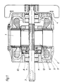
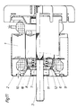
- the asynchronous squirrel-cage rotor motor shown in FIG. 1 consists of a stator 1 and a rotor 2 designed as a squirrel-cage rotor, the shaft of which is rotatably mounted in end shields 4 and 5.
- a brake body 6 is placed over the left end of the shaft 3 in FIG. 1.
- the essentially annular brake body 6 has a sleeve 7, which sits on the shaft 3 with a sliding fit, a base 8 and a wall 9 which projects right up to the facing end face of the rotor 2.
- both the free end of the wall 9 facing the rotor 2 and the facing edge of the rotor 2 are chamfered.
- a helical spring 11 is placed over the sleeve 7, which sits on the shaft 3 with a sliding fit, and presses the brake body 6 away from the rotor against a brake pad 12.
- the brake pad 12 can be a continuous ring which is inserted into a corresponding groove in the end shield 5.
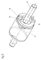
- An alternative embodiment to the arrangement according to FIG. 1 is shown in FIG.
- the brake lining 12 regardless of whether it is a continuous ring or is divided into several ring segments, instead of in the brake body 6 in the bearing plate 5 of the motor, which is fixed to the housing.
- the brake body 6 has annular or partially annular grooves, not shown in the drawings. If the ventilation stroke of the brake body 6 is smaller than the thickness of the brake pad 12, then it is sufficient to simply insert it into the groove of the end shield 5 or the brake body 6 receiving it. This training, which does not stick the brake pad parts, allows a particularly simple replacement of the brake pads.
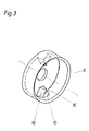
- FIG. 2 in particular shows, two wedge surfaces 14 are provided on the short-circuit ring 13 of the rotor designed as a short-circuit rotor.
- the wedge surfaces 14 lie opposite one another in pairs and are inclined both with respect to a plane perpendicular to the axis of rotation of the rotor 2 and also with respect to a plane passing through the axis of the shaft 3.
- projections 15 with inclined surfaces 16 are provided on the brake body 6 between the wedge surfaces 14 on the short-circuit ring 13.
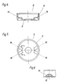
- FIG. 4 to 6 Another embodiment of the brake body is shown in Figures 4 to 6, where the brake body consists of sintered material.
- the brake body 6 has projections 15 with inclined surfaces 16.
- FIGS. 7 and 8 A third embodiment of the brake body is shown in FIGS. 7 and 8.
- the brake body 6 is pressed from sheet metal and is essentially cup-shaped. It can be seen that the projections 15 having the inclined surfaces 16 are pressed out of the base 8 of the cup-shaped brake body 6.
- the braking device according to the invention is provided.
- the device lying to the left of the rotor in FIG. 1 can thus also be arranged on the right side of the motor shown in FIG. 1 or on both sides.
- the brake body can be designed as an annular disk, a ring being placed over the short-circuit ring 13, which carries the wedge surfaces 14, the axial dimension of which is greater than the height of the wedge surfaces.
- the ring can also be shrunk onto the short-circuit ring 13.
- the device according to the invention works as follows:
- the brake body 6 which is made of magnetically conductive material, is predominantly pulled against the rotor by the stray field of the stator 1 until the free end of the wall 9 of the brake body 6 bears against the end face 10 of the rotor.
- the compression spring 11 is compressed somewhat and the brake is released. Even when the engine is idling, if the rotor is running almost synchronously, the stray field is sufficient to apply the brake body 6 and to release the brake, because the compression spring 11 has to be dimensioned to the extent that, after the engine is switched off, the brake body 6 from Rotor can push away.
- a braking force which has the consequence that the brake body 6 rotates relative to the rotor 2 and the inclined surfaces 16 of the brake body run up on the wedge surfaces 14 of the short-circuit ring 13, as a result of which the braking force is further increased.
- This further increase in the braking force takes place completely independently of the strength of the compression spring 11 and has the consequence that the rotor 2 is braked within a very short time.
- the braking time can be adapted to the respective application by changing the inclination of the brake-boosting wedge or inclined surfaces, with flatter wedge and inclined surfaces resulting in a stronger braking force.
- the brake body 6 In order for the brake body 6 to be pulled from the stray field to the rotor 2 and for the brake to be released, the brake body 6 must be at least partially made of magnetically conductive material exist or be connected to a part with magnetically conductive material.
- the invention can also be implemented in motors whose end shields consist of a pressed sheet metal part.
- a bearing plate 5 is shown in FIG. 10, in which the brake pad 12 is fastened by rivets 17.
- the device according to the invention for braking can be used wherever devices equipped with an asynchronous motor are to come to a standstill quickly after switching off for safety reasons. This is for example in lawn mowers, choppers, circular saws and. the like.
- the wedge surfaces and the inclined surfaces have approximately the same radial distance from the axis of rotation of the squirrel-cage rotor as the brake pad.
- the radial distance between the brake pads can also be smaller than that of the wedge surfaces and inclined surfaces.
Landscapes
- Engineering & Computer Science (AREA)
- General Engineering & Computer Science (AREA)
- Mechanical Engineering (AREA)
- Power Engineering (AREA)
- Physics & Mathematics (AREA)
- Electromagnetism (AREA)
- Connection Of Motors, Electrical Generators, Mechanical Devices, And The Like (AREA)
- Braking Arrangements (AREA)
- Control Of Multiple Motors (AREA)
Claims (10)
Applications Claiming Priority (2)
| Application Number | Priority Date | Filing Date | Title |
|---|---|---|---|
| AT0311383A AT378867B (de) | 1983-08-31 | 1983-08-31 | Vorrichtung zum abbremsen von elektromotoren |
| AT3113/83 | 1983-08-31 |
Publications (4)
| Publication Number | Publication Date |
|---|---|
| EP0136282A2 EP0136282A2 (fr) | 1985-04-03 |
| EP0136282A3 EP0136282A3 (en) | 1986-02-26 |
| EP0136282B1 EP0136282B1 (fr) | 1988-07-13 |
| EP0136282B2 true EP0136282B2 (fr) | 1992-03-11 |
Family
ID=3545500
Family Applications (1)
| Application Number | Title | Priority Date | Filing Date |
|---|---|---|---|
| EP84890162A Expired - Lifetime EP0136282B2 (fr) | 1983-08-31 | 1984-08-29 | Dispositif pour freiner des moteurs électriques |
Country Status (3)
| Country | Link |
|---|---|
| EP (1) | EP0136282B2 (fr) |
| AT (2) | AT378867B (fr) |
| DE (1) | DE3472739D1 (fr) |
Families Citing this family (13)
| Publication number | Priority date | Publication date | Assignee | Title |
|---|---|---|---|---|
| DE3407731A1 (de) * | 1984-03-02 | 1985-09-05 | Licentia Patent-Verwaltungs-Gmbh, 6000 Frankfurt | Elektromotor mit automatisch wirkender bremse |
| DE3825114A1 (de) * | 1988-07-23 | 1990-01-25 | Licentia Gmbh | Elektromotor mit selbsttaetig wirkender bremse |
| AT395361B (de) * | 1988-09-21 | 1992-12-10 | Austria Antriebstech | Vorrichtung zum abbremsen von elektromotoren mit kurzschlusslaeufern |
| DE4341889A1 (de) * | 1993-12-08 | 1995-06-14 | Siemens Ag | Kurzschlußläufermotor mit einer stirnseitig angebauten, elektromagnetisch lüftbaren Federdruckbremse |
| BG61889B1 (bg) * | 1996-09-30 | 1998-08-31 | Стаевски, Нанчо М. | Устройство за спиране на електродвигатели |
| FR2764131B1 (fr) * | 1997-05-30 | 1999-07-09 | Leroy Somer Moteurs | Moteur electrique a anneau de court-circuit et pieces de blocages distinctes |
| AT408394B (de) | 1998-05-29 | 2001-11-26 | Atb Austria Antriebstech Ag | Vorrichtung zum abbremsen von elektromotoren |
| FR2779882B1 (fr) * | 1998-06-12 | 2000-08-04 | Leroy Somer | Dispositif de freinage d'un moteur, moteur muni du dispositif et appareil muni de ceux-ci |
| DE10125835A1 (de) * | 2001-05-26 | 2002-11-28 | Valeo Auto Electric Gmbh | Elektrische Antriebseinheit, insbesondere Gleichstromrohrmotor |
| CN1510817A (zh) * | 2002-12-24 | 2004-07-07 | 苏州宝时得电动工具有限公司 | 带制动装置的电动机 |
| KR100619769B1 (ko) | 2005-02-04 | 2006-09-11 | 엘지전자 주식회사 | 역회전 방지기능을 구비한 하이브리드 타입 인덕션모터 |
| DE102005045878A1 (de) * | 2005-09-26 | 2007-03-29 | Knorr-Bremse Systeme für Nutzfahrzeuge GmbH | Vorrichtung zum Abbremsen und/oder zur Drehrichtungsumkehr eines durch einen elektromotorischen Antrieb antreibbaren Antrieb antreibbaren Bauelements |
| WO2012019344A1 (fr) * | 2010-08-11 | 2012-02-16 | Bosch Power Tools (China) Co., Ltd. | Outil électrique portatif avec ensemble frein rapide |
Family Cites Families (3)
| Publication number | Priority date | Publication date | Assignee | Title |
|---|---|---|---|---|
| DE2456091A1 (de) * | 1974-11-27 | 1976-08-12 | Standard Elektrik Lorenz Ag | Induktionsmotor mit bremse |
| DE2751841C3 (de) * | 1977-11-19 | 1981-10-01 | G. Bauknecht Gmbh, 7000 Stuttgart | Kurzschlußläufermotor mit Reibungsbremse |
| DE2946760A1 (de) * | 1979-11-20 | 1981-05-21 | Elektra-Beckum Lubitz & Co, 4470 Meppen | Bremse fuer die umlaufbewegung von asynchron-motoren |
-
1983
- 1983-08-31 AT AT0311383A patent/AT378867B/de not_active IP Right Cessation
-
1984
- 1984-08-29 DE DE8484890162T patent/DE3472739D1/de not_active Expired
- 1984-08-29 EP EP84890162A patent/EP0136282B2/fr not_active Expired - Lifetime
- 1984-08-29 AT AT84890162T patent/ATE35750T1/de not_active IP Right Cessation
Also Published As
| Publication number | Publication date |
|---|---|
| ATA311383A (de) | 1985-02-15 |
| DE3472739D1 (en) | 1988-08-18 |
| ATE35750T1 (de) | 1988-07-15 |
| EP0136282B1 (fr) | 1988-07-13 |
| AT378867B (de) | 1985-10-10 |
| EP0136282A3 (en) | 1986-02-26 |
| EP0136282A2 (fr) | 1985-04-03 |
Similar Documents
| Publication | Publication Date | Title |
|---|---|---|
| EP0136282B2 (fr) | Dispositif pour freiner des moteurs électriques | |
| DE3036091C2 (de) | Elektromotor mit selbsttätig wirkender Bremse | |
| DE19634973C2 (de) | Kupplungs- oder Bremsanordnung | |
| DE2018333B2 (de) | Verschiebeankermotor | |
| DE1114573B (de) | Mit einem Elektromotor zusammengebaute Bremsvorrichtung | |
| DE3508227C1 (de) | Elektromagnetisch betaetigbare Reibungsbrems- und Kupplungsvorrichtung fuer einen elektromotorischen Antrieb,insbesondere fuer Industrie-Naehmaschinen | |
| DE3305632A1 (de) | Kupplungsbremse fuer landmaschinen | |
| DE19719990A1 (de) | Bremse für einen Elektromotor | |
| DE2901784C2 (de) | Nachstellvorrichtung für den Luftspalt einer elektromagnetisch betätigbaren Scheibenbremse | |
| DE2215754A1 (de) | Elektromagnetische Kupplung | |
| DE29706124U1 (de) | Federdruckbremse | |
| DE69203987T2 (de) | Elektrischer Motor mit einer von elektromagnetischen Mitteln betätigten Bremse. | |
| DE19602895B4 (de) | Werkzeug zur Erzeugung einer Lageranordnung für einen Elektromotor | |
| DE1475455A1 (de) | Elektromagnetisch betaetigbare Scheibenbremse | |
| DE8435525U1 (de) | Vorrichtung zum abbremsen von elektromotoren | |
| EP0833428B1 (fr) | Dispositif de freinage pour moteur électrique | |
| DE3214781C2 (de) | Elektromechanisch lüftbare Reibungsbremse | |
| WO2008037569A1 (fr) | Unité d'entraînement électrique avec dispositif pour maintenir en position un arbre | |
| DE2401846A1 (de) | Einrichtung zum selbsttaetigen abbremsen eines elektromotors | |
| DE10060925A1 (de) | Innere Bremskonstruktion für Asynchronmotoren geringer Leistung | |
| DE3910046C2 (fr) | ||
| DE2751841A1 (de) | Kurzschlusslaeufermotor mit reibungsbremse | |
| DE2635075C2 (de) | Klauenpolgenerator | |
| DE8716775U1 (de) | Käfigläufermotor mit Federdruckbremse | |
| EP0892482B1 (fr) | Frein associé à un moteur électrique |
Legal Events
| Date | Code | Title | Description |
|---|---|---|---|
| PUAI | Public reference made under article 153(3) epc to a published international application that has entered the european phase |
Free format text: ORIGINAL CODE: 0009012 |
|
| AK | Designated contracting states |
Designated state(s): AT BE CH DE FR GB IT LI LU NL SE |
|
| PUAL | Search report despatched |
Free format text: ORIGINAL CODE: 0009013 |
|
| AK | Designated contracting states |
Designated state(s): AT BE CH DE FR GB IT LI LU NL SE |
|
| 17P | Request for examination filed |
Effective date: 19860206 |
|
| 17Q | First examination report despatched |
Effective date: 19861114 |
|
| RAP1 | Party data changed (applicant data changed or rights of an application transferred) |
Owner name: AUSTRIA ANTRIEBSTECHNIK G. BAUKNECHT AKTIENGESELLS |
|
| GRAA | (expected) grant |
Free format text: ORIGINAL CODE: 0009210 |
|
| ITF | It: translation for a ep patent filed | ||
| AK | Designated contracting states |
Kind code of ref document: B1 Designated state(s): AT BE CH DE FR GB IT LI LU NL SE |
|
| PG25 | Lapsed in a contracting state [announced via postgrant information from national office to epo] |
Ref country code: GB Free format text: LAPSE BECAUSE OF NON-PAYMENT OF DUE FEES Effective date: 19880713 |
|
| REF | Corresponds to: |
Ref document number: 35750 Country of ref document: AT Date of ref document: 19880715 Kind code of ref document: T |
|
| REF | Corresponds to: |
Ref document number: 3472739 Country of ref document: DE Date of ref document: 19880818 |
|
| ET | Fr: translation filed | ||
| GBV | Gb: ep patent (uk) treated as always having been void in accordance with gb section 77(7)/1977 [no translation filed] | ||
| PLBI | Opposition filed |
Free format text: ORIGINAL CODE: 0009260 |
|
| PLBI | Opposition filed |
Free format text: ORIGINAL CODE: 0009260 |
|
| 26 | Opposition filed |
Opponent name: AEG AKTIENGESELLSCHAFT, BERLIN UND FRANKFURT Effective date: 19890408 |
|
| 26 | Opposition filed |
Opponent name: NUOVA IBMEI S.P.A. Effective date: 19890410 Opponent name: AEG AKTIENGESELLSCHAFT, BERLIN UND FRANKFURT Effective date: 19890408 |
|
| NLR1 | Nl: opposition has been filed with the epo |
Opponent name: AEG AG |
|
| NLR1 | Nl: opposition has been filed with the epo |
Opponent name: NUOVA IBMEI S.P.A. |
|
| ITTA | It: last paid annual fee | ||
| PUAH | Patent maintained in amended form |
Free format text: ORIGINAL CODE: 0009272 |
|
| STAA | Information on the status of an ep patent application or granted ep patent |
Free format text: STATUS: PATENT MAINTAINED AS AMENDED |
|
| 27A | Patent maintained in amended form |
Effective date: 19920311 |
|
| AK | Designated contracting states |
Kind code of ref document: B2 Designated state(s): AT BE CH DE FR GB IT LI LU NL SE |
|
| REG | Reference to a national code |
Ref country code: CH Ref legal event code: AEN |
|
| NLR2 | Nl: decision of opposition | ||
| ITF | It: translation for a ep patent filed | ||
| ET3 | Fr: translation filed ** decision concerning opposition | ||
| NLR3 | Nl: receipt of modified translations in the netherlands language after an opposition procedure | ||
| EPTA | Lu: last paid annual fee | ||
| EAL | Se: european patent in force in sweden |
Ref document number: 84890162.5 |
|
| PGFP | Annual fee paid to national office [announced via postgrant information from national office to epo] |
Ref country code: BE Payment date: 19970805 Year of fee payment: 14 |
|
| PGFP | Annual fee paid to national office [announced via postgrant information from national office to epo] |
Ref country code: NL Payment date: 19970831 Year of fee payment: 14 |
|
| PGFP | Annual fee paid to national office [announced via postgrant information from national office to epo] |
Ref country code: LU Payment date: 19970910 Year of fee payment: 14 |
|
| PG25 | Lapsed in a contracting state [announced via postgrant information from national office to epo] |
Ref country code: LU Free format text: LAPSE BECAUSE OF NON-PAYMENT OF DUE FEES Effective date: 19980829 |
|
| PG25 | Lapsed in a contracting state [announced via postgrant information from national office to epo] |
Ref country code: BE Free format text: LAPSE BECAUSE OF NON-PAYMENT OF DUE FEES Effective date: 19980831 |
|
| BERE | Be: lapsed |
Owner name: AUSTRIA ANTRIEBSTECHNIK G. BAUKNECHT A.G. Effective date: 19980831 |
|
| PG25 | Lapsed in a contracting state [announced via postgrant information from national office to epo] |
Ref country code: NL Free format text: LAPSE BECAUSE OF NON-PAYMENT OF DUE FEES Effective date: 19990301 |
|
| NLV4 | Nl: lapsed or anulled due to non-payment of the annual fee |
Effective date: 19990301 |
|
| PGFP | Annual fee paid to national office [announced via postgrant information from national office to epo] |
Ref country code: SE Payment date: 20030728 Year of fee payment: 20 |
|
| PGFP | Annual fee paid to national office [announced via postgrant information from national office to epo] |
Ref country code: DE Payment date: 20030801 Year of fee payment: 20 |
|
| PGFP | Annual fee paid to national office [announced via postgrant information from national office to epo] |
Ref country code: AT Payment date: 20030814 Year of fee payment: 20 |
|
| PGFP | Annual fee paid to national office [announced via postgrant information from national office to epo] |
Ref country code: FR Payment date: 20030827 Year of fee payment: 20 |
|
| PGFP | Annual fee paid to national office [announced via postgrant information from national office to epo] |
Ref country code: CH Payment date: 20031024 Year of fee payment: 20 |
|
| PG25 | Lapsed in a contracting state [announced via postgrant information from national office to epo] |
Ref country code: LI Free format text: LAPSE BECAUSE OF EXPIRATION OF PROTECTION Effective date: 20040828 Ref country code: CH Free format text: LAPSE BECAUSE OF EXPIRATION OF PROTECTION Effective date: 20040828 |
|
| PG25 | Lapsed in a contracting state [announced via postgrant information from national office to epo] |
Ref country code: AT Free format text: LAPSE BECAUSE OF EXPIRATION OF PROTECTION Effective date: 20040829 |
|
| EUG | Se: european patent has lapsed | ||
| REG | Reference to a national code |
Ref country code: CH Ref legal event code: PL |