EP0136282B2 - Device for braking electric motors - Google Patents
Device for braking electric motors Download PDFInfo
- Publication number
- EP0136282B2 EP0136282B2 EP84890162A EP84890162A EP0136282B2 EP 0136282 B2 EP0136282 B2 EP 0136282B2 EP 84890162 A EP84890162 A EP 84890162A EP 84890162 A EP84890162 A EP 84890162A EP 0136282 B2 EP0136282 B2 EP 0136282B2
- Authority
- EP
- European Patent Office
- Prior art keywords
- brake body
- brake
- squirrel
- cage rotor
- projection
- Prior art date
- Legal status (The legal status is an assumption and is not a legal conclusion. Google has not performed a legal analysis and makes no representation as to the accuracy of the status listed.)
- Expired - Lifetime
Links
- 239000007779 soft material Substances 0.000 claims abstract 2
- 230000006835 compression Effects 0.000 claims description 7
- 238000007906 compression Methods 0.000 claims description 7
- 230000002093 peripheral effect Effects 0.000 claims 1
- 239000002184 metal Substances 0.000 description 5
- 239000004020 conductor Substances 0.000 description 3
- 238000009423 ventilation Methods 0.000 description 3
- 239000000696 magnetic material Substances 0.000 description 2
- 239000000463 material Substances 0.000 description 2
- 238000000034 method Methods 0.000 description 2
- 238000004026 adhesive bonding Methods 0.000 description 1
- 238000006073 displacement reaction Methods 0.000 description 1
- 230000002349 favourable effect Effects 0.000 description 1
- 238000005245 sintering Methods 0.000 description 1
- 210000002105 tongue Anatomy 0.000 description 1
- 238000004804 winding Methods 0.000 description 1
Images


Classifications
-
- F—MECHANICAL ENGINEERING; LIGHTING; HEATING; WEAPONS; BLASTING
- F16—ENGINEERING ELEMENTS AND UNITS; GENERAL MEASURES FOR PRODUCING AND MAINTAINING EFFECTIVE FUNCTIONING OF MACHINES OR INSTALLATIONS; THERMAL INSULATION IN GENERAL
- F16D—COUPLINGS FOR TRANSMITTING ROTATION; CLUTCHES; BRAKES
- F16D55/00—Brakes with substantially-radial braking surfaces pressed together in axial direction, e.g. disc brakes
- F16D55/02—Brakes with substantially-radial braking surfaces pressed together in axial direction, e.g. disc brakes with axially-movable discs or pads pressed against axially-located rotating members
-
- F—MECHANICAL ENGINEERING; LIGHTING; HEATING; WEAPONS; BLASTING
- F16—ENGINEERING ELEMENTS AND UNITS; GENERAL MEASURES FOR PRODUCING AND MAINTAINING EFFECTIVE FUNCTIONING OF MACHINES OR INSTALLATIONS; THERMAL INSULATION IN GENERAL
- F16D—COUPLINGS FOR TRANSMITTING ROTATION; CLUTCHES; BRAKES
- F16D59/00—Self-acting brakes, e.g. coming into operation at a predetermined speed
- F16D59/02—Self-acting brakes, e.g. coming into operation at a predetermined speed spring-loaded and adapted to be released by mechanical, fluid, or electromagnetic means
-
- H—ELECTRICITY
- H02—GENERATION; CONVERSION OR DISTRIBUTION OF ELECTRIC POWER
- H02K—DYNAMO-ELECTRIC MACHINES
- H02K7/00—Arrangements for handling mechanical energy structurally associated with dynamo-electric machines, e.g. structural association with mechanical driving motors or auxiliary dynamo-electric machines
- H02K7/10—Structural association with clutches, brakes, gears, pulleys or mechanical starters
- H02K7/102—Structural association with clutches, brakes, gears, pulleys or mechanical starters with friction brakes
- H02K7/1021—Magnetically influenced friction brakes
- H02K7/1026—Magnetically influenced friction brakes using stray fields
- H02K7/1028—Magnetically influenced friction brakes using stray fields axially attracting the brake armature in the frontal area of the magnetic core
-
- F—MECHANICAL ENGINEERING; LIGHTING; HEATING; WEAPONS; BLASTING
- F16—ENGINEERING ELEMENTS AND UNITS; GENERAL MEASURES FOR PRODUCING AND MAINTAINING EFFECTIVE FUNCTIONING OF MACHINES OR INSTALLATIONS; THERMAL INSULATION IN GENERAL
- F16D—COUPLINGS FOR TRANSMITTING ROTATION; CLUTCHES; BRAKES
- F16D2121/00—Type of actuator operation force
- F16D2121/18—Electric or magnetic
- F16D2121/20—Electric or magnetic using electromagnets
- F16D2121/22—Electric or magnetic using electromagnets for releasing a normally applied brake
-
- F—MECHANICAL ENGINEERING; LIGHTING; HEATING; WEAPONS; BLASTING
- F16—ENGINEERING ELEMENTS AND UNITS; GENERAL MEASURES FOR PRODUCING AND MAINTAINING EFFECTIVE FUNCTIONING OF MACHINES OR INSTALLATIONS; THERMAL INSULATION IN GENERAL
- F16D—COUPLINGS FOR TRANSMITTING ROTATION; CLUTCHES; BRAKES
- F16D2125/00—Components of actuators
- F16D2125/18—Mechanical mechanisms
- F16D2125/20—Mechanical mechanisms converting rotation to linear movement or vice versa
- F16D2125/34—Mechanical mechanisms converting rotation to linear movement or vice versa acting in the direction of the axis of rotation
- F16D2125/36—Helical cams, Ball-rotating ramps
-
- F—MECHANICAL ENGINEERING; LIGHTING; HEATING; WEAPONS; BLASTING
- F16—ENGINEERING ELEMENTS AND UNITS; GENERAL MEASURES FOR PRODUCING AND MAINTAINING EFFECTIVE FUNCTIONING OF MACHINES OR INSTALLATIONS; THERMAL INSULATION IN GENERAL
- F16D—COUPLINGS FOR TRANSMITTING ROTATION; CLUTCHES; BRAKES
- F16D2127/00—Auxiliary mechanisms
- F16D2127/08—Self-amplifying or de-amplifying mechanisms
- F16D2127/10—Self-amplifying or de-amplifying mechanisms having wedging elements
Definitions
- the invention relates to a device for braking electric motors with short-circuit rotors, with an essentially cup-shaped brake body, which consists at least partially of soft magnetic material and which has at least one inclined surface, which is provided on the short-circuit ring, flat wedge surface which is oriented obliquely to the axis of the short-circuit rotor , is turned, wherein the inclined surface is provided on a protrusion towards the short-circuit ring of the cup-shaped brake body, which protrudes from the bottom of the brake body into the interior of the brake body, and wherein between the brake body and a housing-fixed component of the electric motor, a brake pad and between the brake body and the squirrel-cage rotor is provided with a pressing spring.
- Brakes for electric motors which serve to bring the electric motor to a standstill as quickly as possible after switching off, are known.
- a disadvantage of the known mechanical brakes is the fact that they cannot be integrated inside the motors to be braked and often have a complicated structure.
- Electronic brakes have also been proposed, which in turn have the disadvantage that they fail in the event of a power failure or complete interruption of the circuit.
- a disadvantage of the arrangement known from DE-A-2 335 954 is finally that the entire squirrel-cage rotor with its large mass must be displaced when the brake is actuated and released. For all these reasons, the device for braking electric motors known from DE-A-2 335 954 is disadvantageous and only works sluggishly.
- a device for braking electric motors with squirrel-cage rotors which has an essentially cup-shaped brake body which is at least partially made of soft magnetic material and which has at least one inclined surface which has an actuating member connected to the squirrel-cage rotor in a rotationally fixed manner is turned, wherein between the brake body and a housing-fixed component of the electric motor, a brake pad and between the brake body and the squirrel-cage rotor, a spring pressing the brake body against the brake pad are arranged.
- DE-A-3 036 091 (cf. page 7, 1st paragraph) still proposed to form the return spring with kinked ends with which it engages in the anchor plate and in the motor. This is to ensure that the actuating bolt inserted through the shaft of the squirrel-cage rotor is always in the deepest area of the inclined surfaces when the motor is at a standstill.
- a device with the features of the preamble of claim 1 is known from DE-A-29 19 672.
- the inclined surfaces are designed as partial cylindrical surfaces and cooperate with wedge surfaces recessed in the short-circuit ring.
- the brake body acts in DE-A-29 19 672 via a brake disc which is axially displaceable relative to the brake body is, and which is pushed away from this by a second spring, together with the brake pad.
- the invention has for its object to provide a robust, mechanical coasting brake that works regardless of network fluctuations or load conditions of the motor.
- this is achieved in a device of the type mentioned in that the spring presses the brake body directly against the brake pad, that the wedge surface is provided on a protrusion arranged on the short-circuit ring of the squirrel-cage rotor, that the inclined surface and the axis of the squirrel-cage rotor in the same Oblique position as the wedge surface on the short-circuit ring is aligned and that the inclined surface and the wedge surface are inclined with respect to the bottom and the wall of the brake body.
- the run-out brake according to the invention is released when the motor is switched on in that the brake body is attracted axially primarily by the stray field of the stator that arises and additionally by that of the rotor of the asynchronous motor equipped with a short-circuit rotor winding and thus does not press against the brake pad.
- the brake body is pushed away from the rotor by the compression spring and there is friction between the brake body, the brake lining and the housing-fixed component against which the brake lining rests. Due to this frictional force, the braking body is additionally pushed away from the rotor due to the wedge and inclined surfaces acting on one another and the braking force is increased.
- the braking force generated when the engine is switched off can be adapted to the prevailing conditions by specifically selecting the inclination of the wedge surfaces and, correspondingly, the inclined surfaces.
- lawn mower motors in be braked only 2 to 3 seconds to a complete stop. This time value is far below the generally required value of 5 seconds.
- the embodiment of the braking device according to the invention is characterized by particular robustness and largely wear-free of the sliding surfaces, so that the material of the short-circuit ring can simultaneously serve as a sliding partner in the area of the inclined surfaces without disadvantage.
- the brake according to the invention can also be characterized in that the brake lining from the axis of the squirrel-cage rotor has essentially the same radial distance as the wedge surface and the inclined surface.
- the fact that the radial distance between the braking surfaces is essentially the same as the distance between the actuating surfaces and the axis of the squirrel-cage rotor results in more favorable lever ratios than in the known devices.
- the device according to the invention is independent of the direction of rotation of the rotor if at least one pair of opposing wedge surfaces on the short circuit ring and Brake body is provided at least one projection engaging between the wedge surfaces and having two inclined surfaces.
- the brake lining is designed as a ring, which is divided, if necessary, as a single or multiple part, and which is inserted into an optionally interrupted groove in a component of the electric motor fixed to the housing or in the brake body.
- the depth of the groove is greater than the ventilation stroke of the brake body and that the thickness of the brake pad is greater than the depth of the groove.
- the brake lining parts which have, for example, a kidney-shaped outline, into the grooves in the brake body or in the fixed housing part, e.g. a bearing plate of the motor.
- the projection provided on the brake body projects into the interior of the brake body both from the floor and from the wall of the brake body.
- This embodiment is particularly suitable for brake bodies produced in the sintering process.
- the projection provided on the brake body can be pressed out of the brake body.
- This embodiment is preferably suitable for cup-shaped brake bodies produced using the deep-drawing process.
- the ring-shaped brake body will normally sit with some play over the shaft of the squirrel-cage rotor.
- a sleeve with a sliding fit over the shaft of the short-circuit rotor is provided in the center of the pot. It can be provided that the spring loading the brake body is inserted over the sleeve. This results in an even more precise guidance of the brake body.
- the ventilation stroke of the brake body can be limited in a particularly simple manner in the device according to the invention by the substantially cylindrical jacket-shaped wall of the brake body projecting beyond the projection carrying the wedge surface and projecting up to the facing end face of the short-circuit rotor, the free edge of the wall being chamfered and a correspondingly chamfered one Edge of the end face of the squirrel-cage rotor is opposite.
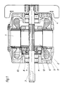
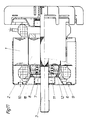
- the asynchronous squirrel-cage rotor motor shown in FIG. 1 consists of a stator 1 and a rotor 2 designed as a squirrel-cage rotor, the shaft of which is rotatably mounted in end shields 4 and 5.
- a brake body 6 is placed over the left end of the shaft 3 in FIG. 1.
- the essentially annular brake body 6 has a sleeve 7, which sits on the shaft 3 with a sliding fit, a base 8 and a wall 9 which projects right up to the facing end face of the rotor 2.
- both the free end of the wall 9 facing the rotor 2 and the facing edge of the rotor 2 are chamfered.
- a helical spring 11 is placed over the sleeve 7, which sits on the shaft 3 with a sliding fit, and presses the brake body 6 away from the rotor against a brake pad 12.
- the brake pad 12 can be a continuous ring which is inserted into a corresponding groove in the end shield 5.
- An alternative embodiment to the arrangement according to FIG. 1 is shown in FIG.
- the brake lining 12 regardless of whether it is a continuous ring or is divided into several ring segments, instead of in the brake body 6 in the bearing plate 5 of the motor, which is fixed to the housing.
- the brake body 6 has annular or partially annular grooves, not shown in the drawings. If the ventilation stroke of the brake body 6 is smaller than the thickness of the brake pad 12, then it is sufficient to simply insert it into the groove of the end shield 5 or the brake body 6 receiving it. This training, which does not stick the brake pad parts, allows a particularly simple replacement of the brake pads.
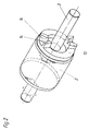
- FIG. 2 in particular shows, two wedge surfaces 14 are provided on the short-circuit ring 13 of the rotor designed as a short-circuit rotor.
- the wedge surfaces 14 lie opposite one another in pairs and are inclined both with respect to a plane perpendicular to the axis of rotation of the rotor 2 and also with respect to a plane passing through the axis of the shaft 3.
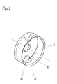
- projections 15 with inclined surfaces 16 are provided on the brake body 6 between the wedge surfaces 14 on the short-circuit ring 13.
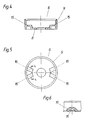
- FIG. 4 to 6 Another embodiment of the brake body is shown in Figures 4 to 6, where the brake body consists of sintered material.
- the brake body 6 has projections 15 with inclined surfaces 16.
- FIGS. 7 and 8 A third embodiment of the brake body is shown in FIGS. 7 and 8.
- the brake body 6 is pressed from sheet metal and is essentially cup-shaped. It can be seen that the projections 15 having the inclined surfaces 16 are pressed out of the base 8 of the cup-shaped brake body 6.
- the braking device according to the invention is provided.
- the device lying to the left of the rotor in FIG. 1 can thus also be arranged on the right side of the motor shown in FIG. 1 or on both sides.
- the brake body can be designed as an annular disk, a ring being placed over the short-circuit ring 13, which carries the wedge surfaces 14, the axial dimension of which is greater than the height of the wedge surfaces.
- the ring can also be shrunk onto the short-circuit ring 13.
- the device according to the invention works as follows:
- the brake body 6 which is made of magnetically conductive material, is predominantly pulled against the rotor by the stray field of the stator 1 until the free end of the wall 9 of the brake body 6 bears against the end face 10 of the rotor.
- the compression spring 11 is compressed somewhat and the brake is released. Even when the engine is idling, if the rotor is running almost synchronously, the stray field is sufficient to apply the brake body 6 and to release the brake, because the compression spring 11 has to be dimensioned to the extent that, after the engine is switched off, the brake body 6 from Rotor can push away.
- a braking force which has the consequence that the brake body 6 rotates relative to the rotor 2 and the inclined surfaces 16 of the brake body run up on the wedge surfaces 14 of the short-circuit ring 13, as a result of which the braking force is further increased.
- This further increase in the braking force takes place completely independently of the strength of the compression spring 11 and has the consequence that the rotor 2 is braked within a very short time.
- the braking time can be adapted to the respective application by changing the inclination of the brake-boosting wedge or inclined surfaces, with flatter wedge and inclined surfaces resulting in a stronger braking force.
- the brake body 6 In order for the brake body 6 to be pulled from the stray field to the rotor 2 and for the brake to be released, the brake body 6 must be at least partially made of magnetically conductive material exist or be connected to a part with magnetically conductive material.
- the invention can also be implemented in motors whose end shields consist of a pressed sheet metal part.
- a bearing plate 5 is shown in FIG. 10, in which the brake pad 12 is fastened by rivets 17.
- the device according to the invention for braking can be used wherever devices equipped with an asynchronous motor are to come to a standstill quickly after switching off for safety reasons. This is for example in lawn mowers, choppers, circular saws and. the like.
- the wedge surfaces and the inclined surfaces have approximately the same radial distance from the axis of rotation of the squirrel-cage rotor as the brake pad.
- the radial distance between the brake pads can also be smaller than that of the wedge surfaces and inclined surfaces.
Landscapes
- Engineering & Computer Science (AREA)
- General Engineering & Computer Science (AREA)
- Mechanical Engineering (AREA)
- Power Engineering (AREA)
- Physics & Mathematics (AREA)
- Electromagnetism (AREA)
- Connection Of Motors, Electrical Generators, Mechanical Devices, And The Like (AREA)
- Braking Arrangements (AREA)
- Control Of Multiple Motors (AREA)
Abstract
Description
Die Erfindung betrifft eine Vorrichtung zum Abbremsen von Elektromotoren mit Kurzschlußläufern, mit einem im wesentlichen topfförmigen Bremskörper, der wenigstens teilweise aus weichmagnetischem Werkstoff besteht und der mindestens eine Schrägfläche aufweist, die einer am Kurzschlußring vorgesehenen, ebenen Keilfläche, die zur Achse des Kurzschlußläufers schräg ausgerichtet ist, zugekehrt ist, wobei die Schrägfläche an einem zum Kurzschlußring hin ragenden Vorsprung des topfförmigen Bremskörpers vorgesehen ist, der vom Boden des Bremskörpers in das Innere des Bremskörpers ragt, und wobei zwischen dem Bremskörper und einem gehäusefesten Bauteil des Elektromotors ein Bremsbelag und zwischen dem Bremskörper und dem Kurzschlußläufer eine drückende Feder vorgesehen ist.The invention relates to a device for braking electric motors with short-circuit rotors, with an essentially cup-shaped brake body, which consists at least partially of soft magnetic material and which has at least one inclined surface, which is provided on the short-circuit ring, flat wedge surface which is oriented obliquely to the axis of the short-circuit rotor , is turned, wherein the inclined surface is provided on a protrusion towards the short-circuit ring of the cup-shaped brake body, which protrudes from the bottom of the brake body into the interior of the brake body, and wherein between the brake body and a housing-fixed component of the electric motor, a brake pad and between the brake body and the squirrel-cage rotor is provided with a pressing spring.
Bremsen für Elektromotoren, die dazu dienen, den Elektromotor nach dem Abschalten möglichst rasch zum Stillstand zu bringen, sind bekannt. Nachteilig bei den bekannten mechanischen Bremsen ist der Umstand, daß sie nicht im Inneren der abzubremsenden Motore integriert werden können und oft einen komplizierten Aufbau besitzen. Es sind auch elektronische Bremsen vorgeschlagen worden, die wiederum den Nachteil haben, daß sie bei Netzausfall oder vollständiger Unterbrechung des Stromkreises versagen.Brakes for electric motors, which serve to bring the electric motor to a standstill as quickly as possible after switching off, are known. A disadvantage of the known mechanical brakes is the fact that they cannot be integrated inside the motors to be braked and often have a complicated structure. Electronic brakes have also been proposed, which in turn have the disadvantage that they fail in the event of a power failure or complete interruption of the circuit.
Es sind auch schon mechanische Bremsen für Elektromotore mit Kurzschlußläufern bekannt geworden, bei welchen der Bremskörper vom Streufeld des Kurzschlußläufers entgegen der Kraft einer Rückstellfeder gelüftet wird. Nachteilig bei diesen aus den Dokumenten DE-A-2 456 091, DE-B-2 751 841 und DE-A-2 946 760 bekannten Bremsen ist der Umstand, daß der Bremskörper ausschließlich durch die Kraft der Rückstellfeder in seine Wirkstellung gedrückt wird, wobei aber die Federkraft nur so groß gewählt werden kann, daß sie vom Streufeld des Motors überwunden werden kann.Mechanical brakes for electric motors with squirrel-cage rotors have also become known in which the brake body is released from the stray field of the squirrel-cage rotor against the force of a return spring. A disadvantage of these brakes known from documents DE-A-2 456 091, DE-B-2 751 841 and DE-A-2 946 760 is the fact that the brake body is pressed into its active position solely by the force of the return spring, but the spring force can only be chosen so large that it can be overcome by the stray field of the motor.
Bei der aus der DE-A-2 335 954 bekannten Vorrichtung für Bremsmotoren ist der Läufer mit seiner Welle ausschließlich über einen gleichzeitig als Betätigungsorgan für die Bremse dienenden Stift gekuppelt. Diese Ausbildung setzt voraus, daß der Läufer axial verschiebbar auf der Welle sitzt. Uberdies hat sich gezeigt, daß bei einer derartigen Ausbildung einer Bremse für Elektromotoren der Betätigungsstift an der Schrägfläche nach dem Abbremsen des Motors hängenbleibt, so daß der Läufer in der Bremsstellung zurückgehalten wird und der Motor nicht wieder anlaufen kann. Ein weiterer Nachteil dieser bekannten Vorrichtung besteht darin, daß das Verschieben des Läufers in die Bremsstellung bzw. das Wiederanheben des Läufers entgegen der Reibung zwischen am Läufer vorgesehenen Armen und Nuten an einer Scheibe, in welche die Arme eingreifen, verschoben werden muß.In the device for brake motors known from DE-A-2 335 954, the rotor is coupled with its shaft exclusively via a pin which also serves as an actuator for the brake. This training requires that the rotor is axially displaceable on the shaft. Furthermore, it has been shown that with such a design of a brake for electric motors, the actuating pin sticks to the inclined surface after the motor has been braked, so that the rotor is held back in the braking position and the motor cannot start again. Another disadvantage of this known device is that the displacement of the rotor in the braking position or the lifting of the rotor against the friction between the arms provided on the rotor and grooves on a disc in which the arms engage must be moved.
Nachteilig bei der aus der DE-A-2 335 954 bekannten Anordnung ist schließlich, daß beim Betätigen und beim Lösen der Bremse der gesamte Kurzschlußläufer mit seiner großen Masse verschoben werden muß. Aus all diesen Gründen ist die aus der DE-A-2 335 954 bekannte Vorrichtung zum Abbremsen von Elektromotoren nachteilig und arbeitet nur träge.A disadvantage of the arrangement known from DE-A-2 335 954 is finally that the entire squirrel-cage rotor with its large mass must be displaced when the brake is actuated and released. For all these reasons, the device for braking electric motors known from DE-A-2 335 954 is disadvantageous and only works sluggishly.
Aus der DE-A-3 036 091 ist eine Vorrichtung zum Abbremsen von Elektromotoren mit Kurzschlußläufern bekannt, die einen im wesentlichen topfförmigen Bremskörper aufweisen, der wenigstens teilweise aus weichmagnetischem Werkstoff besteht und der mindestens eine Schrägfläche aufweist, die einem mit dem Kurzschlußläufer drehfest verbundenen Betätigungsorgan zugekehrt ist, wobei zwischen dem Bremskörper und einem gehäusefesten Bauteil des Elektromotors ein Bremsbelag und zwischen dem Bremskörper und dem Kurzschlußläufer eine den Bremskörper gegen den Bremsbelag drückende Feder angeordnet sind.From DE-A-3 036 091 a device for braking electric motors with squirrel-cage rotors is known which has an essentially cup-shaped brake body which is at least partially made of soft magnetic material and which has at least one inclined surface which has an actuating member connected to the squirrel-cage rotor in a rotationally fixed manner is turned, wherein between the brake body and a housing-fixed component of the electric motor, a brake pad and between the brake body and the squirrel-cage rotor, a spring pressing the brake body against the brake pad are arranged.
Nachteilig bei dieser bekannten Vorrichtung ist einmal, daß eine große Anzahl von Bauteilen, nämlich ein topfförmiges Bremsorgan, eine in diesem verschiebbar geführte Betätigungsscheibe mit Schrägflächen, eine Druckfeder zwischen der Betätigungsscheibe und dem Topfboden, ein Verschlußdeckel für den Bremskörper, der mit diesem durch vier Befestigungsorgane zu verbinden ist, ein Betätigungsbolzen, und eine weitere Druckfeder im Motor untergebracht werden müssen. Ein weiterer Nachteil der aus der DE-A-3 036 091 bekannten Vorrichtung besteht darin, daß zur Betätigung der Bremse der durch die Welle des Kurzschlußläufers gesteckte Betätigungsbolzen mit Schrägflächen zusammenwirkt. Es ergeben sich dadurch die bereits im Zusammenhang mit der DE-A-2 335 954 geschilderten Nachteile. Schließlich besteht ein Nachteil noch darin, daß die Bremsfläche und somit die Bremsbeläge von der Achse des Kurzschlußläufers einen erheblich größeren Abstand aufweisen als die Betätigungsorgane (Betätigungsstift und Schrägflächen).One disadvantage of this known device is that a large number of components, namely a cup-shaped braking member, a slidably guided in this actuating disc with inclined surfaces, a compression spring between the actuating disc and the pot base, a cover for the brake body, which is to be connected to this by four fastening elements, an actuating bolt, and another compression spring must be accommodated in the engine. Another disadvantage of the device known from DE-A-3 036 091 is that the actuating bolt inserted through the shaft of the short-circuit rotor interacts with inclined surfaces for actuating the brake. This results in the disadvantages already described in connection with DE-A-2 335 954. Finally, there is a disadvantage that the braking surface and thus the brake pads are at a considerably greater distance from the axis of the squirrel-cage rotor than the actuating members (actuating pin and inclined surfaces).
Um die oben im Zusammenhang mit der aus der DE-A-2 335 954 bekannten Bremse erwähnte Gefahr des Hängenbleibens des Betätigungsstiftes an der Schrägfläche zu verringern, ist in der DE-A-3 036 091 (vgl. Seite 7, 1. Absatz) noch vorgeschlagen, die Rückstellfeder mit abgeknickten Enden auszubilden, mit denen sie in die Ankerplatte und in den Motor eingreift. Damit soll gewährleistet werden, daß sich der durch die Welle des Kurzschlußläufers gesteckte Betätigungsbolzen während des Stillstandes des Motors stets im tiefsten Bereich der Schrägflächen befindet.In order to reduce the risk of the actuating pin getting caught on the inclined surface mentioned above in connection with the brake known from DE-A-2 335 954, DE-A-3 036 091 (cf.
Eine Vorrichtung mit den Merkmalen des Oberbegriffes des Patentanspruches 1 ist aus der DE-A-29 19 672 bekannt. Bei dieser bekannten Vorrichtung sind die Schrägflächen als Teilzylinderflächen ausgebildet und wirken mit im Kurzschlußring versenkten Keilflächen zusammen. Der Bremskörper wirkt bei der DE-A-29 19 672 über eine Bremsscheibe, die gegenüber dem Bremskörper achsial verschiebbar ist, und die durch eine zweite Feder von diesem weggedrückt wird, mit dem Bremsbelag zusammen.A device with the features of the preamble of claim 1 is known from DE-A-29 19 672. In this known device, the inclined surfaces are designed as partial cylindrical surfaces and cooperate with wedge surfaces recessed in the short-circuit ring. The brake body acts in DE-A-29 19 672 via a brake disc which is axially displaceable relative to the brake body is, and which is pushed away from this by a second spring, together with the brake pad.
Der Erfindung liegt die Aufgabe zugrunde, eine robuste, mechanische Auslaufbremse anzugeben, die unabhängig von auftretenden Netzschwankungen oder Belastungszuständen des Motors funktioniert.The invention has for its object to provide a robust, mechanical coasting brake that works regardless of network fluctuations or load conditions of the motor.
Erfindungsgemäß wird dies bei einer Vorrichtung der eingangs genannten Gattung dadurch erreicht, daß die Feder den Bremskörper unmittelbar gegen den Bremsbelag drückt, daß die Keilfläche an einem am Kurzschlußring des Kurzschlußläufers angeordneten Vorsprung vorgesehen ist, daß die Schrägfläche eben und zur Achse des Kurzschlußläufers in der gleichen Schräglage wie die Keilfläche am Kurzschlußring ausgerichtet ist und daß die Schrägfläche und die Keilfläche gegenüber dem Boden und der Wand des Bremskörpers geneigt sind.According to the invention this is achieved in a device of the type mentioned in that the spring presses the brake body directly against the brake pad, that the wedge surface is provided on a protrusion arranged on the short-circuit ring of the squirrel-cage rotor, that the inclined surface and the axis of the squirrel-cage rotor in the same Oblique position as the wedge surface on the short-circuit ring is aligned and that the inclined surface and the wedge surface are inclined with respect to the bottom and the wall of the brake body.
Die erfindungsgemäße Auslaufbremse wird beim Einschalten des Motors dadurch gelüftet, daß der Bremskörper vornehmlich durch das entstehende Streufeld des Stators und zusätzlich durch jenes des mit einer Kurzschlußläuferwicklung ausgerüsteten Rotors des Asynchronmotors axial angezogen wird und somit nicht gegen den Bremsbelag drückt. Beim Abschalten des Motors, in gleicher Weise bei völligem Netzausfall, wird der Bremskörper von der Druckfeder vom Rotor weggedrückt und es entsteht Reibung zwischen dem Bremskörper, dem Bremsbelag und dem gehäusefesten Bauteil, gegen welche der Bremsbelag anliegt. Durch diese Reibungskraft wird der Bremskörper zufolge der aufeinander einwirkenden Keil- und Schrägflächen zusätzlich vom Rotor weggedrückt und die Bremskraft erhöht. Durch gezielte Wahl der Neigung der Keilflächen und sinngemäß der Schrägflächen kann die beim Abschalten des Motors entstehende Bremskraft den jeweils gegebenen Verhältnissen angepaßt werden. Mit der erfindungsgemäßen Vorrichtung können beispielsweise Rasenmähermotoren in nur 2 bis 3 Sekunden bis zum völligen Stillstand abgebremst werden. Dieser Zeitwert liegt weit unter dem allgemein geforderten Wert von 5 Sekunden.The run-out brake according to the invention is released when the motor is switched on in that the brake body is attracted axially primarily by the stray field of the stator that arises and additionally by that of the rotor of the asynchronous motor equipped with a short-circuit rotor winding and thus does not press against the brake pad. When the motor is switched off, in the same way in the event of a complete power failure, the brake body is pushed away from the rotor by the compression spring and there is friction between the brake body, the brake lining and the housing-fixed component against which the brake lining rests. Due to this frictional force, the braking body is additionally pushed away from the rotor due to the wedge and inclined surfaces acting on one another and the braking force is increased. The braking force generated when the engine is switched off can be adapted to the prevailing conditions by specifically selecting the inclination of the wedge surfaces and, correspondingly, the inclined surfaces. With the device according to the invention, for example, lawn mower motors in be braked only 2 to 3 seconds to a complete stop. This time value is far below the generally required value of 5 seconds.
Vorteile der erfindungsgemäßen Ausbildung gegenüber dem Stand der Technik liegen einmal in der geringen Anzahl der benötigten Bauteile, überdies ist es bei der erfindungsgemäßen Vorrichtung nicht mehr notwendig, mit der Welle des Kurzschlußläufers Stifte od. dgl. Betätigungsorgane zu verbinden, sondern die Betätigungsorgane für die Bremse sind unmittelbar am Kurzschlußring des Kurzschlußläufers vorgesehen und können bevorzugt mit diesem einstückig ausgebildet sein. Dadurch, daß bei der erfindungsgemäßen Vorrichtung ebene Schrägflächen mit ebenen Keilflächen, statt wie beim Stand der Technik ebene Flächen mit runden Betätigungsstiften oder teilzylindrischen Flächen, zusammenwirken, besteht auch keine Gefahr, daß sich die Betätigungsorgane mit dem Bremskörper verklemmen.Advantages of the design according to the invention over the prior art lie in the small number of components required, moreover, it is no longer necessary in the device according to the invention to connect pins or the like actuators to the shaft of the squirrel-cage rotor, but rather the actuators for the brake are provided directly on the short-circuit ring of the short-circuit rotor and can preferably be formed in one piece with this. Characterized in that in the device according to the invention, flat inclined surfaces with flat wedge surfaces, instead of as in the prior art flat surfaces with round actuating pins or partially cylindrical surfaces, cooperate, there is also no risk that the actuating members jam with the brake body.
Die erfindungsgemäße Ausführungsform der Bremsvorrichtung zeichnet sich durch besondere Robustheit und weitgehende Verschleißfreiheit der Gleitflächen aus, so daß der Werkstoff des Kurzschlußringes ohne Nachteil gleichzeitig als Gleitpartner im Bereich der Schrägflächen dienen kann.The embodiment of the braking device according to the invention is characterized by particular robustness and largely wear-free of the sliding surfaces, so that the material of the short-circuit ring can simultaneously serve as a sliding partner in the area of the inclined surfaces without disadvantage.
Die erfindungsgemäße Bremse kann sich weiters dadurch auszeichnen, daß der Bremsbelag von der Achse des Kurzschlußläufers im wesentlichen den gleichen Radialabstand besitzt wie die Keilfläche und die Schrägfläche. Dadurch, daß der Radialabstand der Bremsflächen im wesentlichen gleich groß ist wie der Abstand der Betätigungsflächen von der Achse des Kurzschlußläufers, ergeben sich günstigere Hebelverhältnisse als bei den bekannten Vorrichtungen.The brake according to the invention can also be characterized in that the brake lining from the axis of the squirrel-cage rotor has essentially the same radial distance as the wedge surface and the inclined surface. The fact that the radial distance between the braking surfaces is essentially the same as the distance between the actuating surfaces and the axis of the squirrel-cage rotor results in more favorable lever ratios than in the known devices.
Die erfindungsgemäße Vorrichtung ist von der Drehrichtung des Rotors unabhängig, wenn am Kurzschlußring wenigstens ein Paar einander gegenüberliegender Keilflächen und am Bremskörper wenigstens ein zwischen die Keilflächen eingreifender, zwei Schrägflächen aufweisender Vorsprung vorgesehen ist.The device according to the invention is independent of the direction of rotation of the rotor if at least one pair of opposing wedge surfaces on the short circuit ring and Brake body is provided at least one projection engaging between the wedge surfaces and having two inclined surfaces.
Im Rahmen der Erfindung kann vorgesehen sein, daß der Bremsbelag als gegebenenfalls, wie an sich bekannt, ein- oder mehrfach unterteilter Ring ausgebildet ist, der in eine gegebenenfalls unterbrochene Nut in einem gehäusefesten Bauteil des Elektromotors oder im Bremskörper eingesetzt ist.In the context of the invention it can be provided that the brake lining is designed as a ring, which is divided, if necessary, as a single or multiple part, and which is inserted into an optionally interrupted groove in a component of the electric motor fixed to the housing or in the brake body.
In Weiterbildung dieser Ausführungsform kann erfindungsgemäß vorgesehen sein, daß die Tiefe der Nut größer ist als der Lüftungshub des Bremskörpers und daß die Dicke des Bremsbelages größer ist als die Tiefe der Nut. Bei dieser Ausführungsform genügt es, wenn die Bremsbelagteile, die beispielsweise eine nierenförmige Umrißform besitzen, in die Nuten im Bremskörper oder im feststehenden Gehäuseteil, z.B. einem Lagerschild des Motors, eingelegt werden.In a further development of this embodiment it can be provided according to the invention that the depth of the groove is greater than the ventilation stroke of the brake body and that the thickness of the brake pad is greater than the depth of the groove. In this embodiment, it is sufficient if the brake lining parts, which have, for example, a kidney-shaped outline, into the grooves in the brake body or in the fixed housing part, e.g. a bearing plate of the motor.
In einer weiteren Ausführungsform der Erfindung ist vorgesehen, daß der am Bremskörper vorgesehene Vorsprung sowohl von dem Boden als auch von der Wand des Bremskörpers ausgehend in das Innere des Bremskörpers ragt. Diese Ausführungsform eignet sich besonders für im Sinterverfahren hergestellte Bremskörper.In a further embodiment of the invention it is provided that the projection provided on the brake body projects into the interior of the brake body both from the floor and from the wall of the brake body. This embodiment is particularly suitable for brake bodies produced in the sintering process.
Im Rahmen der Erfindung kann der am Bremskörper vorgesehene Vorsprung aus dem Bremskörper hochgepresst sein. Diese Ausführungsform eignet sich bevorzugt für im Tiefziehverfahren hergestellte topfförmige Bremskörper.In the context of the invention, the projection provided on the brake body can be pressed out of the brake body. This embodiment is preferably suitable for cup-shaped brake bodies produced using the deep-drawing process.
Normalerweise wird der ringförmige Bremskörper mit etwas Spiel über der Welle des Kurzschlussläufers sitzen. Es ist aber auch eine Ausführungsform denkbar, bei der in der Mitte des Topfes eine mit Gleitsitz über die Welle des Kurzschlussläufers gesteckte Hülse vorgesehen ist. Hiebei kann vorgesehen sein, dass die den Bremskörper belastende Feder über die Hülse gesteckt ist. Dadurch wird eine noch exaktere Führung des Bremskörpers erreicht.The ring-shaped brake body will normally sit with some play over the shaft of the squirrel-cage rotor. However, an embodiment is also conceivable in which a sleeve with a sliding fit over the shaft of the short-circuit rotor is provided in the center of the pot. It can be provided that the spring loading the brake body is inserted over the sleeve. This results in an even more precise guidance of the brake body.
Der Lüftungshub des Bremskörpers kann bei der erfindungsgemässen Vorrichtung besonders einfach dadurch begrenzt werden, dass die im wesentlichen zylindermantelförmige Wand des Bremskörpers den die Keilfläche tragenden vorsprung übergreifend bis vor die zugekehrte Stirnfläche des Kurzschlussläufers ragt, wobei der freie Rand der Wand abgeschrägt ist und einer entsprechend abgeschrägten Kante der stirnfläche des Kurzschlussläufers gegenüberliegt.The ventilation stroke of the brake body can be limited in a particularly simple manner in the device according to the invention by the substantially cylindrical jacket-shaped wall of the brake body projecting beyond the projection carrying the wedge surface and projecting up to the facing end face of the short-circuit rotor, the free edge of the wall being chamfered and a correspondingly chamfered one Edge of the end face of the squirrel-cage rotor is opposite.
Weitere Einzelheiten und Merkmale der Erfindung ergeben sich aus der nachstehenden Beschreibung der in den Zeichnungen wiedergegebenen Ausführungsbeispiele. Es zeigt:
- Figur 1 im Schnitt einen mit der erfindungsgemässen Vorrichtung ausgerüsteten Asynchronmotor mit Kurzschlussläufer,
Figur 2 den Kurzschlussläufer des Motors aus Figur 1 in Schrägansicht,Figur 3 in Schrägansicht einen topfförmigen Bremskörper,Figur Figur 7 und 8 einen aus Blech gepressten Bremskörper,Figur 9 eine Variante der Anordnung des Bremsbelages im Lagerschild des Motors,Figur 10 eine Ausführungsform mit einem als Blechteil ausgebildeten Lagerschild und- Fig. 11 einen Motor mit einem aus Blech geprägten Lagerschild.
- FIG. 1 shows in section an asynchronous motor with a short-circuit rotor equipped with the device according to the invention,
- FIG. 2 shows the squirrel-cage rotor of the motor from FIG. 1 in an oblique view,
- FIG. 3 an oblique view of a cup-shaped brake body,
- FIGS. 4, 5 and 6 show a further embodiment of a brake body,
- 7 and 8 a brake body pressed from sheet metal,
- FIG. 9 shows a variant of the arrangement of the brake lining in the end shield of the motor,
- 10 shows an embodiment with a bearing plate designed as a sheet metal part and
- 11 shows a motor with a bearing plate embossed from sheet metal.
Der in Figur 1 gezeigte Asynchron-Kurzschlussläufermotor besteht aus einem Stator 1 und einem als Kurzschlussläufer ausgebildeten Rotor 2, dessen Welle in Lagerschilden 4 und 5 drehbar gelagert ist. Über das in Figur 1 linke Ende der Welle 3 ist ein Bremskörper 6 gesteckt. Der im wesentlichen ringförmige Bremskörper 6 besitzt eine Hülse 7, die mit Gleitsitz auf der Welle 3 sitzt, einen Boden 8 und eine Wand 9, die bis unmittelbar vor die zugekehrte Stirnfläche des Rotors 2 ragt. Wie aus Figur 1 weiters ersichtlich, ist sowohl das freie, dem Rotor 2 zugekehrte Ende der Wand 9 als auch die zugekehrte Kante des Rotors 2 abgeschrägt.The asynchronous squirrel-cage rotor motor shown in FIG. 1 consists of a stator 1 and a
Über die Hülse 7, die mit Gleitsitz auf der Welle 3 sitzt, ist eine Schraubenfeder 11 gesteckt, die den Bremskörper 6 vom Rotor weg gegen einen Bremsbelag 12 drückt.A
Der Bremsbelag 12 kann ein durchgehender Ring sein, der in eine entsprechende Nut des Lagerschildes 5 eingesetzt ist. Eine zur Anordnung nach Figur 1 alternative Ausführungsform ist in Figur 9 gezeigt. Es ist aber auch möglich, den Bremsbelag 12, ganz gleich, ob dieser ein durchgehender Ring ist oder in mehrere Ringsegmente unterteilt ist, statt im gehäusefesten Lagerschild 5 des Motors auch im Bremskörper 6 vorzusehen. In diesem Fall weist der Bremskörper 6 in den Zeichnungen nicht gezeigte, ringförmige oder teilringförmige Nuten auf. Wenn der Lüftungshub des Bremskörpers 6 kleiner ist als die Stärke des Bremsbelages 12, dann genügt es, diesen in die ihn aufnehmende Nut des Lagerschildes 5 oder des Bremskörpers 6 einfach einzulegen. Diese Ausbildung, die ohne Festkleben der Bremsbelagteile auskommt, gestatt ein besonders einfaches Auswechseln der Bremsbeläge.The
Wie insbesondere Figur 2 zeigt, sind am Kurzschlussring 13 des als Kurzschlussläufer ausgebildeten Rotors 2 Keilflächen 14 vorgesehen. Wie ebenfalls aus Figur 2 ersichtlich, liegen die Keilflächen 14 einander paarweise gegenüber und sind sowohl gegenüber einer zur Drehachse des Rotors 2 senkrechten Ebene als auch gegenüber einer durch die Achse der Welle 3 gehenden Ebene geneigt.As FIG. 2 in particular shows, two
Aus Figur 3 ist ersichtlich, dass am Bremskörper 6 zwischen die Keilflächen 14 am Kurzschlussring 13 eingreifende Vorsprünge 15 mit schrägflächen 16 vorgesehen sind.It can be seen from FIG. 3 that
Eine andere Ausführungsform des Bremskörpers ist in den Figuren 4 bis 6 gezeigt, wobei dort der Bremskörper aus Sinterwerkstoff besteht. Auch hier besitzt der Bremskörper 6 vorsprünge 15 mit Schrägflächen 16.Another embodiment of the brake body is shown in Figures 4 to 6, where the brake body consists of sintered material. Here, too, the
Eine dritte Ausführungsform des Bremskörpers zeigen die Figuren 7 und 8. Bei dieser Ausführungsform ist der Bremskörper 6 aus Blech gepresst und im wesentlichen topfförmig ausgebildet. Es ist ersichtlich, dass die die Schrägflächen 16 aufweisenden Vorsprünge 15 aus dem Boden 8 des topfförmigen Bremskörpers 6 hochgepresst sind.A third embodiment of the brake body is shown in FIGS. 7 and 8. In this embodiment, the
Obwohl in den gezeigten Ausführungsbeispielen mehrere Keilflächen 14 und dementsprechend mehrere Schrägflächen 16 vorgesehen sind, sind auch Ausführungsformen mit weniger oder mehr als vier Schrägflächen 16 denkbar.Although a plurality of wedge surfaces 14 and, accordingly, a plurality of
Des weiteren ist es gleichgültig, auf welcher Seite des Rotors 2 die erfindungsgemässe Vorrichtung zum Abbremsen vorgesehen ist. Es kann somit die in Figur 1 links vom Rotor liegende Vorrichtung genauso an der rechten Seite des in Figur 1 gezeigten Motors oder an beiden Seiten angeordnet sein.Furthermore, it does not matter on which side of the
Gemäss einer weiteren, nicht gezeigten Ausführungsform kann der Bremskörper als Ringscheibe ausgebildet sein, wobei über den Kurzschlussring 13, der die Keilflächen 14 trägt, ein Ring gesteckt ist, dessen axiale Abmessung grösser ist als die Höhe der Keilflächen. Der Ring kann auch auf den Kurzschlussring 13 aufgeschrumpft sein.According to a further embodiment, not shown, the brake body can be designed as an annular disk, a ring being placed over the short-
Die erfindungsgemässe Vorrichtung arbeitet wie folgt:The device according to the invention works as follows:
Sobald der Motor eingeschaltet wird, wird der aus magnetisch leitendem Werkstoff bestehende Bremskörper 6 vorwiegend vom Streufeld des Stators 1 gegen den Rotor gezogen, bis das freie Ende der Wand 9 des Bremskörpers 6 gegen die stirnfläche 10 des Rotors anliegt. Dabei wird die Druckfeder 11 etwas zusammengedrückt und die Bremse ist gelüftet. Auch bei Leerlauf des Motors, wenn der Rotor also nahezu synchron läuft, genügt das Streufeld, den Bremskörper 6 anzuziehen und die Bremse zu lüften, weil die Druckfeder 11 gerade so stark dimensioniert sein braucht, dass sie nach dem Abschalten des Motors den Bremskörper 6 vom Rotor weg drücken kann. Sobald der Bremskörper 6 vom Rotor 2 weggedrückt wird, entsteht zwischen Bremskörper 6, Bremsbelag 12 und dem gehäusefesten Teil, z.B. dem Lagerschild 5, eine Bremskraft, die zur Folge hat, dass sich der Bremskörper 6 gegenüber dem Rotor 2 verdreht und die Schrägflächen 16 des Bremskörpers auf den Keilflächen 14 des Kurzschlussringes 13 auflaufen, wodurch die Bremskraft weiter erhöht wird. Diese weitere Erhöhung der Bremskraft erfolgt vollständig unabhängig von der Stärke der Druckfeder 11 und hat zur Folge, dass der Rotor 2 innerhalb kürzester Zeit abgebremst wird. Dabei kann die Abbremszeit durch Verändern der Neigung der bremsverstärkenden Keil- bzw. Schrägflächen dem jeweiligen Anwendungsfall angepasst werden, wobei flacher ausgebildete Keil- und Schrägflächen eine stärkere Bremskraft zur Folge haben.As soon as the motor is switched on, the
Damit der Bremskörper 6 vom Streufeld zum Rotor 2 hin gezogen und damit die Bremse gelüftet werden kann, muss der Bremskörper 6 mindestens teilweise aus magnetisch leitendem Werkstoff bestehen oder mit einem Teil mit magnetisch leitendem Werkstoff verbunden sein.In order for the
Die Erfindung kann auch bei Motoren verwirklicht werden, deren Lagerschilde aus einem Blechpressteil bestehen. Ein derartiges Lagerschild 5 zeigt Figur 10, bei dem der Bremsbelag 12 durch Nieten 17 befestigt ist. Es ist aber durchaus möglich, den Bremsbelag 12 durch Kleben zu befestigen und/oder, wie in Figur 11 gezeigt, innerhalb von Haltezungen 18 einzulegen.The invention can also be implemented in motors whose end shields consist of a pressed sheet metal part. Such a
Die erfindungsgemässe Vorrichtung zum Abbremsen kann überall dort angewandt werden, wo mit einem Asynchronmotor ausgerüstete Geräte aus sicherheitsgründen nach dem Abschalten rasch zum stillstand kommen sollen. Dies ist beispielsweise bei Rasenmähern, Häckslern, Kreissägen u. dgl. der Fall.The device according to the invention for braking can be used wherever devices equipped with an asynchronous motor are to come to a standstill quickly after switching off for safety reasons. This is for example in lawn mowers, choppers, circular saws and. the like.
Bei zweipoligen Motoren (etwa 300 U/min) haben die Keilflächen und die Schrägflächen etwa den gleichen Radialabstand von der Drehachse des Kurzschlussläufers wie der Bremsbelag. Bei grösseren Kurzschlussringabmessungen, in der Regel bei höherpoligen Motoren, bei welchen die gleichen mechanischen Elemente (z. B. Lagerschild) verwendet werden, kann der Radialabstand des Bremsbelages auch kleiner sein als der der Keilflächen und Schrägflächen.In the case of two-pole motors (approximately 300 rpm), the wedge surfaces and the inclined surfaces have approximately the same radial distance from the axis of rotation of the squirrel-cage rotor as the brake pad. In the case of larger short-circuit ring dimensions, usually in the case of motors with higher poles, in which the same mechanical elements (e.g. end shield) are used, the radial distance between the brake pads can also be smaller than that of the wedge surfaces and inclined surfaces.
Claims (10)
Applications Claiming Priority (2)
| Application Number | Priority Date | Filing Date | Title |
|---|---|---|---|
| AT0311383A AT378867B (en) | 1983-08-31 | 1983-08-31 | DEVICE FOR BRAKING ELECTRIC MOTORS |
| AT3113/83 | 1983-08-31 |
Publications (4)
| Publication Number | Publication Date |
|---|---|
| EP0136282A2 EP0136282A2 (en) | 1985-04-03 |
| EP0136282A3 EP0136282A3 (en) | 1986-02-26 |
| EP0136282B1 EP0136282B1 (en) | 1988-07-13 |
| EP0136282B2 true EP0136282B2 (en) | 1992-03-11 |
Family
ID=3545500
Family Applications (1)
| Application Number | Title | Priority Date | Filing Date |
|---|---|---|---|
| EP84890162A Expired - Lifetime EP0136282B2 (en) | 1983-08-31 | 1984-08-29 | Device for braking electric motors |
Country Status (3)
| Country | Link |
|---|---|
| EP (1) | EP0136282B2 (en) |
| AT (2) | AT378867B (en) |
| DE (1) | DE3472739D1 (en) |
Families Citing this family (13)
| Publication number | Priority date | Publication date | Assignee | Title |
|---|---|---|---|---|
| DE3407731A1 (en) * | 1984-03-02 | 1985-09-05 | Licentia Patent-Verwaltungs-Gmbh, 6000 Frankfurt | Electric motor with an automatically acting brake |
| DE3825114A1 (en) * | 1988-07-23 | 1990-01-25 | Licentia Gmbh | ELECTRIC MOTOR WITH SELF-ACTING BRAKE |
| AT395361B (en) * | 1988-09-21 | 1992-12-10 | Austria Antriebstech | DEVICE FOR BRAKING ELECTRIC MOTORS WITH SHORT-TERM RUNNERS |
| DE4341889A1 (en) * | 1993-12-08 | 1995-06-14 | Siemens Ag | Short-circuit rotor motor with an electromagnetically ventilated spring pressure brake mounted on the front |
| BG61889B1 (en) * | 1996-09-30 | 1998-08-31 | Стаевски, Нанчо М. | ELECTRIC SHOCK DISTRIBUTION DEVICE |
| FR2764131B1 (en) * | 1997-05-30 | 1999-07-09 | Leroy Somer Moteurs | ELECTRIC MOTOR WITH SHORT-CIRCUIT RING AND SEPARATE LOCKING PARTS |
| AT408394B (en) | 1998-05-29 | 2001-11-26 | Atb Austria Antriebstech Ag | DEVICE FOR BRAKING ELECTRIC MOTORS |
| FR2779882B1 (en) * | 1998-06-12 | 2000-08-04 | Leroy Somer | BRAKING DEVICE OF A MOTOR, MOTOR PROVIDED WITH THE DEVICE, AND APPARATUS PROVIDED WITH SAME |
| DE10125835A1 (en) * | 2001-05-26 | 2002-11-28 | Valeo Auto Electric Gmbh | Electric drive unit especially tubular DC motor e.g. for roller blinds and awnings, includes device for rotational protection of drive shaft during idling of drive unit |
| CN1510817A (en) * | 2002-12-24 | 2004-07-07 | 苏州宝时得电动工具有限公司 | Motor with brake |
| KR100619769B1 (en) | 2005-02-04 | 2006-09-11 | 엘지전자 주식회사 | Hybrid type induction motor with reverse rotation prevention |
| DE102005045878A1 (en) * | 2005-09-26 | 2007-03-29 | Knorr-Bremse Systeme für Nutzfahrzeuge GmbH | Device for braking and / or reversing the direction of rotation of a drivable by an electric motor drive drive component |
| WO2012019344A1 (en) * | 2010-08-11 | 2012-02-16 | Bosch Power Tools (China) Co., Ltd. | Portable power tool with quick brake assembly |
Family Cites Families (3)
| Publication number | Priority date | Publication date | Assignee | Title |
|---|---|---|---|---|
| DE2456091A1 (en) * | 1974-11-27 | 1976-08-12 | Standard Elektrik Lorenz Ag | Induction motor with sprung coaxial brake disc - has friction material coated end face of rotor and needing no brake excitation winding |
| DE2751841C3 (en) * | 1977-11-19 | 1981-10-01 | G. Bauknecht Gmbh, 7000 Stuttgart | Squirrel cage motor with friction brake |
| DE2946760A1 (en) * | 1979-11-20 | 1981-05-21 | Elektra-Beckum Lubitz & Co, 4470 Meppen | Spindle-mounted brake for async. motor - has cup-shaped magnetic moving part pushed by spring towards fixed part on fan housing |
-
1983
- 1983-08-31 AT AT0311383A patent/AT378867B/en not_active IP Right Cessation
-
1984
- 1984-08-29 DE DE8484890162T patent/DE3472739D1/en not_active Expired
- 1984-08-29 EP EP84890162A patent/EP0136282B2/en not_active Expired - Lifetime
- 1984-08-29 AT AT84890162T patent/ATE35750T1/en not_active IP Right Cessation
Also Published As
| Publication number | Publication date |
|---|---|
| ATA311383A (en) | 1985-02-15 |
| DE3472739D1 (en) | 1988-08-18 |
| ATE35750T1 (en) | 1988-07-15 |
| EP0136282B1 (en) | 1988-07-13 |
| AT378867B (en) | 1985-10-10 |
| EP0136282A3 (en) | 1986-02-26 |
| EP0136282A2 (en) | 1985-04-03 |
Similar Documents
| Publication | Publication Date | Title |
|---|---|---|
| EP0136282B2 (en) | Device for braking electric motors | |
| DE3036091C2 (en) | Electric motor with automatic brake | |
| DE19634973C2 (en) | Clutch or brake assembly | |
| DE2018333B2 (en) | Sliding armature motor | |
| DE1114573B (en) | Braking device assembled with an electric motor | |
| DE3508227C1 (en) | Electromagnetically actuable friction brake and clutch device for an electric motor drive, especially for industrial sewing machines | |
| DE3305632A1 (en) | CLUTCH BRAKE FOR AGRICULTURAL MACHINERY | |
| DE19719990A1 (en) | Brake for electric motor, esp. for moving control elements in motor vehicle | |
| DE2901784C2 (en) | Adjustment device for the air gap of an electromagnetically operated disc brake | |
| DE2215754A1 (en) | Electromagnetic clutch | |
| DE29706124U1 (en) | Spring pressure brake | |
| DE69203987T2 (en) | Electric motor with a brake actuated by electromagnetic means. | |
| DE19602895B4 (en) | Tool for generating a bearing assembly for an electric motor | |
| DE1475455A1 (en) | Electromagnetically operated disc brake | |
| DE8435525U1 (en) | DEVICE FOR BRAKING ELECTRIC MOTORS | |
| EP0833428B1 (en) | Electric motor braking device | |
| DE3214781C2 (en) | Electromechanically released friction brake | |
| WO2008037569A1 (en) | Electric drive unit having a device for maintaining the position of a shaft | |
| DE2401846A1 (en) | DEVICE FOR AUTOMATIC BRAKING OF AN ELECTRIC MOTOR | |
| DE10060925A1 (en) | Internal brake construction for asynchronous motors of minimal power, has in rim body, extended milled out item in which flux-conducting tube is located connected with rim body and flux-conducting disc | |
| DE3910046C2 (en) | ||
| DE2751841A1 (en) | SHORT-CIRCUIT RUNNER MOTOR WITH FRICTION BRAKE | |
| DE2635075C2 (en) | Claw pole generator | |
| DE8716775U1 (en) | Squirrel cage motor with spring pressure brake | |
| EP0892482B1 (en) | Brake arrangement associated with an electric motor |
Legal Events
| Date | Code | Title | Description |
|---|---|---|---|
| PUAI | Public reference made under article 153(3) epc to a published international application that has entered the european phase |
Free format text: ORIGINAL CODE: 0009012 |
|
| AK | Designated contracting states |
Designated state(s): AT BE CH DE FR GB IT LI LU NL SE |
|
| PUAL | Search report despatched |
Free format text: ORIGINAL CODE: 0009013 |
|
| AK | Designated contracting states |
Designated state(s): AT BE CH DE FR GB IT LI LU NL SE |
|
| 17P | Request for examination filed |
Effective date: 19860206 |
|
| 17Q | First examination report despatched |
Effective date: 19861114 |
|
| RAP1 | Party data changed (applicant data changed or rights of an application transferred) |
Owner name: AUSTRIA ANTRIEBSTECHNIK G. BAUKNECHT AKTIENGESELLS |
|
| GRAA | (expected) grant |
Free format text: ORIGINAL CODE: 0009210 |
|
| ITF | It: translation for a ep patent filed | ||
| AK | Designated contracting states |
Kind code of ref document: B1 Designated state(s): AT BE CH DE FR GB IT LI LU NL SE |
|
| PG25 | Lapsed in a contracting state [announced via postgrant information from national office to epo] |
Ref country code: GB Free format text: LAPSE BECAUSE OF NON-PAYMENT OF DUE FEES Effective date: 19880713 |
|
| REF | Corresponds to: |
Ref document number: 35750 Country of ref document: AT Date of ref document: 19880715 Kind code of ref document: T |
|
| REF | Corresponds to: |
Ref document number: 3472739 Country of ref document: DE Date of ref document: 19880818 |
|
| ET | Fr: translation filed | ||
| GBV | Gb: ep patent (uk) treated as always having been void in accordance with gb section 77(7)/1977 [no translation filed] | ||
| PLBI | Opposition filed |
Free format text: ORIGINAL CODE: 0009260 |
|
| PLBI | Opposition filed |
Free format text: ORIGINAL CODE: 0009260 |
|
| 26 | Opposition filed |
Opponent name: AEG AKTIENGESELLSCHAFT, BERLIN UND FRANKFURT Effective date: 19890408 |
|
| 26 | Opposition filed |
Opponent name: NUOVA IBMEI S.P.A. Effective date: 19890410 Opponent name: AEG AKTIENGESELLSCHAFT, BERLIN UND FRANKFURT Effective date: 19890408 |
|
| NLR1 | Nl: opposition has been filed with the epo |
Opponent name: AEG AG |
|
| NLR1 | Nl: opposition has been filed with the epo |
Opponent name: NUOVA IBMEI S.P.A. |
|
| ITTA | It: last paid annual fee | ||
| PUAH | Patent maintained in amended form |
Free format text: ORIGINAL CODE: 0009272 |
|
| STAA | Information on the status of an ep patent application or granted ep patent |
Free format text: STATUS: PATENT MAINTAINED AS AMENDED |
|
| 27A | Patent maintained in amended form |
Effective date: 19920311 |
|
| AK | Designated contracting states |
Kind code of ref document: B2 Designated state(s): AT BE CH DE FR GB IT LI LU NL SE |
|
| REG | Reference to a national code |
Ref country code: CH Ref legal event code: AEN |
|
| NLR2 | Nl: decision of opposition | ||
| ITF | It: translation for a ep patent filed | ||
| ET3 | Fr: translation filed ** decision concerning opposition | ||
| NLR3 | Nl: receipt of modified translations in the netherlands language after an opposition procedure | ||
| EPTA | Lu: last paid annual fee | ||
| EAL | Se: european patent in force in sweden |
Ref document number: 84890162.5 |
|
| PGFP | Annual fee paid to national office [announced via postgrant information from national office to epo] |
Ref country code: BE Payment date: 19970805 Year of fee payment: 14 |
|
| PGFP | Annual fee paid to national office [announced via postgrant information from national office to epo] |
Ref country code: NL Payment date: 19970831 Year of fee payment: 14 |
|
| PGFP | Annual fee paid to national office [announced via postgrant information from national office to epo] |
Ref country code: LU Payment date: 19970910 Year of fee payment: 14 |
|
| PG25 | Lapsed in a contracting state [announced via postgrant information from national office to epo] |
Ref country code: LU Free format text: LAPSE BECAUSE OF NON-PAYMENT OF DUE FEES Effective date: 19980829 |
|
| PG25 | Lapsed in a contracting state [announced via postgrant information from national office to epo] |
Ref country code: BE Free format text: LAPSE BECAUSE OF NON-PAYMENT OF DUE FEES Effective date: 19980831 |
|
| BERE | Be: lapsed |
Owner name: AUSTRIA ANTRIEBSTECHNIK G. BAUKNECHT A.G. Effective date: 19980831 |
|
| PG25 | Lapsed in a contracting state [announced via postgrant information from national office to epo] |
Ref country code: NL Free format text: LAPSE BECAUSE OF NON-PAYMENT OF DUE FEES Effective date: 19990301 |
|
| NLV4 | Nl: lapsed or anulled due to non-payment of the annual fee |
Effective date: 19990301 |
|
| PGFP | Annual fee paid to national office [announced via postgrant information from national office to epo] |
Ref country code: SE Payment date: 20030728 Year of fee payment: 20 |
|
| PGFP | Annual fee paid to national office [announced via postgrant information from national office to epo] |
Ref country code: DE Payment date: 20030801 Year of fee payment: 20 |
|
| PGFP | Annual fee paid to national office [announced via postgrant information from national office to epo] |
Ref country code: AT Payment date: 20030814 Year of fee payment: 20 |
|
| PGFP | Annual fee paid to national office [announced via postgrant information from national office to epo] |
Ref country code: FR Payment date: 20030827 Year of fee payment: 20 |
|
| PGFP | Annual fee paid to national office [announced via postgrant information from national office to epo] |
Ref country code: CH Payment date: 20031024 Year of fee payment: 20 |
|
| PG25 | Lapsed in a contracting state [announced via postgrant information from national office to epo] |
Ref country code: LI Free format text: LAPSE BECAUSE OF EXPIRATION OF PROTECTION Effective date: 20040828 Ref country code: CH Free format text: LAPSE BECAUSE OF EXPIRATION OF PROTECTION Effective date: 20040828 |
|
| PG25 | Lapsed in a contracting state [announced via postgrant information from national office to epo] |
Ref country code: AT Free format text: LAPSE BECAUSE OF EXPIRATION OF PROTECTION Effective date: 20040829 |
|
| EUG | Se: european patent has lapsed | ||
| REG | Reference to a national code |
Ref country code: CH Ref legal event code: PL |