EP0136086B1 - Nichtkontaktierender Drehmomentfühler - Google Patents
Nichtkontaktierender Drehmomentfühler Download PDFInfo
- Publication number
- EP0136086B1 EP0136086B1 EP84305819A EP84305819A EP0136086B1 EP 0136086 B1 EP0136086 B1 EP 0136086B1 EP 84305819 A EP84305819 A EP 84305819A EP 84305819 A EP84305819 A EP 84305819A EP 0136086 B1 EP0136086 B1 EP 0136086B1
- Authority
- EP
- European Patent Office
- Prior art keywords
- magnetic
- shaft
- generating
- detecting
- ribbon
- Prior art date
- Legal status (The legal status is an assumption and is not a legal conclusion. Google has not performed a legal analysis and makes no representation as to the accuracy of the status listed.)
- Expired
Links
- 230000005291 magnetic effect Effects 0.000 claims description 118
- 230000004907 flux Effects 0.000 claims description 17
- 229910000808 amorphous metal alloy Inorganic materials 0.000 claims description 14
- 239000000696 magnetic material Substances 0.000 claims description 10
- 229920006395 saturated elastomer Polymers 0.000 claims description 9
- 239000000203 mixture Substances 0.000 claims description 5
- 230000008878 coupling Effects 0.000 claims description 4
- 238000010168 coupling process Methods 0.000 claims description 4
- 238000005859 coupling reaction Methods 0.000 claims description 4
- 229910052782 aluminium Inorganic materials 0.000 claims description 2
- 229910052787 antimony Inorganic materials 0.000 claims description 2
- 229910052804 chromium Inorganic materials 0.000 claims description 2
- 229910052802 copper Inorganic materials 0.000 claims description 2
- 229910052733 gallium Inorganic materials 0.000 claims description 2
- 229910052732 germanium Inorganic materials 0.000 claims description 2
- 229910052737 gold Inorganic materials 0.000 claims description 2
- 229910052735 hafnium Inorganic materials 0.000 claims description 2
- 229910052738 indium Inorganic materials 0.000 claims description 2
- 229910052741 iridium Inorganic materials 0.000 claims description 2
- 229910052745 lead Inorganic materials 0.000 claims description 2
- 229910052748 manganese Inorganic materials 0.000 claims description 2
- 229910052750 molybdenum Inorganic materials 0.000 claims description 2
- 229910052758 niobium Inorganic materials 0.000 claims description 2
- 229910052763 palladium Inorganic materials 0.000 claims description 2
- 229910052697 platinum Inorganic materials 0.000 claims description 2
- 229910052761 rare earth metal Inorganic materials 0.000 claims description 2
- 150000002910 rare earth metals Chemical class 0.000 claims description 2
- 229910052702 rhenium Inorganic materials 0.000 claims description 2
- 229910052707 ruthenium Inorganic materials 0.000 claims description 2
- 229910052709 silver Inorganic materials 0.000 claims description 2
- 229910052715 tantalum Inorganic materials 0.000 claims description 2
- 229910052718 tin Inorganic materials 0.000 claims description 2
- 229910052721 tungsten Inorganic materials 0.000 claims description 2
- 229910052720 vanadium Inorganic materials 0.000 claims description 2
- 229910052725 zinc Inorganic materials 0.000 claims description 2
- 229910052726 zirconium Inorganic materials 0.000 claims description 2
- 238000005070 sampling Methods 0.000 claims 6
- 229910052719 titanium Inorganic materials 0.000 claims 1
- 230000035699 permeability Effects 0.000 description 8
- 238000004804 winding Methods 0.000 description 6
- 229910045601 alloy Inorganic materials 0.000 description 4
- 239000000956 alloy Substances 0.000 description 4
- 230000004044 response Effects 0.000 description 4
- 230000005540 biological transmission Effects 0.000 description 3
- 238000010586 diagram Methods 0.000 description 3
- 230000005415 magnetization Effects 0.000 description 3
- 238000004519 manufacturing process Methods 0.000 description 3
- 229910052751 metal Inorganic materials 0.000 description 3
- 239000002184 metal Substances 0.000 description 3
- 229910001030 Iron–nickel alloy Inorganic materials 0.000 description 2
- 229910000676 Si alloy Inorganic materials 0.000 description 2
- 230000008859 change Effects 0.000 description 2
- 230000006835 compression Effects 0.000 description 2
- 238000007906 compression Methods 0.000 description 2
- 229910001004 magnetic alloy Inorganic materials 0.000 description 2
- 239000000463 material Substances 0.000 description 2
- 229910000889 permalloy Inorganic materials 0.000 description 2
- 229910000702 sendust Inorganic materials 0.000 description 2
- 229910017082 Fe-Si Inorganic materials 0.000 description 1
- 229910017133 Fe—Si Inorganic materials 0.000 description 1
- 230000002411 adverse Effects 0.000 description 1
- 230000003321 amplification Effects 0.000 description 1
- 230000007423 decrease Effects 0.000 description 1
- 230000003111 delayed effect Effects 0.000 description 1
- 238000001514 detection method Methods 0.000 description 1
- 230000000694 effects Effects 0.000 description 1
- 239000003302 ferromagnetic material Substances 0.000 description 1
- 230000001788 irregular Effects 0.000 description 1
- 238000000034 method Methods 0.000 description 1
- 238000003199 nucleic acid amplification method Methods 0.000 description 1
- 238000005096 rolling process Methods 0.000 description 1
- 239000002023 wood Substances 0.000 description 1
Images


Classifications
-
- G—PHYSICS
- G01—MEASURING; TESTING
- G01L—MEASURING FORCE, STRESS, TORQUE, WORK, MECHANICAL POWER, MECHANICAL EFFICIENCY, OR FLUID PRESSURE
- G01L3/00—Measuring torque, work, mechanical power, or mechanical efficiency, in general
- G01L3/02—Rotary-transmission dynamometers
- G01L3/04—Rotary-transmission dynamometers wherein the torque-transmitting element comprises a torsionally-flexible shaft
- G01L3/10—Rotary-transmission dynamometers wherein the torque-transmitting element comprises a torsionally-flexible shaft involving electric or magnetic means for indicating
- G01L3/109—Rotary-transmission dynamometers wherein the torque-transmitting element comprises a torsionally-flexible shaft involving electric or magnetic means for indicating involving measuring phase difference of two signals or pulse trains
-
- G—PHYSICS
- G01—MEASURING; TESTING
- G01L—MEASURING FORCE, STRESS, TORQUE, WORK, MECHANICAL POWER, MECHANICAL EFFICIENCY, OR FLUID PRESSURE
- G01L3/00—Measuring torque, work, mechanical power, or mechanical efficiency, in general
- G01L3/02—Rotary-transmission dynamometers
- G01L3/04—Rotary-transmission dynamometers wherein the torque-transmitting element comprises a torsionally-flexible shaft
- G01L3/10—Rotary-transmission dynamometers wherein the torque-transmitting element comprises a torsionally-flexible shaft involving electric or magnetic means for indicating
- G01L3/101—Rotary-transmission dynamometers wherein the torque-transmitting element comprises a torsionally-flexible shaft involving electric or magnetic means for indicating involving magnetic or electromagnetic means
- G01L3/102—Rotary-transmission dynamometers wherein the torque-transmitting element comprises a torsionally-flexible shaft involving electric or magnetic means for indicating involving magnetic or electromagnetic means involving magnetostrictive means
- G01L3/103—Details about the magnetic material used
-
- G—PHYSICS
- G01—MEASURING; TESTING
- G01L—MEASURING FORCE, STRESS, TORQUE, WORK, MECHANICAL POWER, MECHANICAL EFFICIENCY, OR FLUID PRESSURE
- G01L3/00—Measuring torque, work, mechanical power, or mechanical efficiency, in general
- G01L3/02—Rotary-transmission dynamometers
- G01L3/04—Rotary-transmission dynamometers wherein the torque-transmitting element comprises a torsionally-flexible shaft
- G01L3/10—Rotary-transmission dynamometers wherein the torque-transmitting element comprises a torsionally-flexible shaft involving electric or magnetic means for indicating
- G01L3/101—Rotary-transmission dynamometers wherein the torque-transmitting element comprises a torsionally-flexible shaft involving electric or magnetic means for indicating involving magnetic or electromagnetic means
- G01L3/105—Rotary-transmission dynamometers wherein the torque-transmitting element comprises a torsionally-flexible shaft involving electric or magnetic means for indicating involving magnetic or electromagnetic means involving inductive means
Definitions
- the present invention relates to a torque sensor of the noncontact type.
- Harada et al in "A New Torque Transducer Using Stress Sensitive Amorphous Ribbons" and Japanese Patent Disclosure (Kokai) 57-211,030 describes a torque sensor in which an amorphous magnetic ribbon is bonded to a shaft, and in which a coil assembly is provided coaxially with the axis of the shaft.
- the torque sensor generates a magnetic flux parallel with its axis which measures the permeability of the amorphous magnetic ribbon which varies in response to the torque applied to the shaft.
- This torque sensor prevents the possibility of an erroneous detection based on the irregular magnetic properties of the material.
- a relatively large reverse magnetic field is produced when the coil assembly generates a magnetic flux in parallel with the axis of a shaft.
- a magnetic ribbon having a sheet shape is bonded to a shaft where its torque is sensed.
- the magnetic ribbon have been applied with an induced magnetic anisotropy in a direction of an angle 6 to the circumferential direction of the shaft.
- a core member having end faces opposite to the magnetic ribbon is provided.
- An exciting coil for producing a magnetic flux is wound around the core member, and a detecting coil for detecting the magnetic flux, which is introduced into the core member through the magnetic ribbon along the circumferential direction of the shaft, is wound around the magnetic core.
- the torque applied to the shaft is present as variations in the magnetic permeability of the magnetic ribbon and the voltage detected by the detecting coil. Therefore, the torque can be sensed as the voltage detected by the detecting coil.
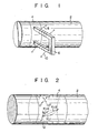
- a magnetic sheet preferably an amorphous magnetic ribbon 4 is arranged along the circumferential direction of a shaft 2 and is bonded to the shaft 2 to which rotary torque is applied. Further, an induced magnetic anistropy is applied in advance to the amorphous magnetic ribbon 4 in the direction of angle 6 to the circumferential direction of the ribbon.
- a U-shaped magnetic core 6 formed of a magnetic material, for example, an oxide magnetic material is disposed in the vicinity of the shaft 2, and the end faces of the core 6 are opposite to the amorphous magnetic ribbon 4 through gaps.
- An exciting coil 8 for generating a magnetic flux and a detecting coil 10 for detecting the magnetic flux depending upon the magnetic permeability of the amorphous magnetic ribbon 4 are wound around the U-shaped magnetic core 6.
- Such a torque sensor of a noncontact type detects the torque according to the principle which will be described.
- an induced magnetic anisotropy K U1 is applied in advance to the amorphous magnetic ribbon 4 in the direction of angle 6>45° along the circumferential direction of the shaft 2, and its saturated magnetostriction is to be ⁇ s >0.
- a distortion stress generated at the shaft 2 is transmitted to the amorphous magnetic ribbon 4.
- a tension + 0 is produced in a direction of +45° to the circumferential direction in the magnetic ribbon 4
- a compression stress - 0 is produced in a direction of -45° to the circumferential direction.
- a magnetic anisotropy K U2 is induced by the magnetostriction in the magnetic ribbon 2 in response to these tensions +a and the compression stress - 0 . Therefore, a magnetic anistropy Ku o is produced as the resultant vector of the magnetic anisotropies K U1 and Ku 2 .
- the magnetic permeability depends upon the direction of the vector of the magnetic anisotropy K U3 , and the variations in the magnetic permeability are present as variations in the mutual inductance in the magnetic ribbon 2 between the exciting coil 8 and the detecting coil 10 in the sensor as shown in Figure 1.
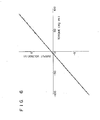
- the variations in the torque applied to the shaft 2 are detected as variations in the phase of the AC voltage generated from the detecting coil 10 instead of change of the AC voltage generated from the detecting coil 10, which is measured by the voltmeter.
- the inductance L in the magnetic ribbon 2 between the exciting coil 8 and the detecting coil 10 varies due to the variations in the torque applied to the shaft 2.
- the AC voltage generated from the detecting coil 10 is produced by a delay in the phase by ⁇ L to the AC voltage applied to the exciting coil 8, where the variations in the inductance L are AL, and the frequency of the AC voltage applied to the exciting coil 8 is w.
- This phase delay ⁇ L is detected in the circuit in Figure 4 by utilizing the above relation.
- an exciting coil 8 is connected to an oscillator 12 for generating the voltage of a predetermined frequency w, and is connected to a Schmitt trigger circuit 14 for converting the AC voltage generated from the detecting coil 10 to a rectangular wave.
- this Schmitt trigger circuit 14 generates a rectangular signal having a frequency ⁇ and is delayed in phase by ⁇ L by the voltage generated from the oscillator 12.
- This rectangular signal is supplied to an exclusive OR 16 connected to a rectangular wave oscillating circuit 15 which generates a rectangular wave signal having a frequency w with the same phase as the voltage generated from the oscillator 12. Therefore, a pulse signal having a phase delay time T corresponding to the phase delay ⁇ L is generated from the exclusive OR 16.
- This pulse signal is supplied to an AND gate 20 connected to a clock pulse generator 18 which generates a clock pulse, and the pulse width of the pulse signal is converted by the AND gate 20 to a clock pulse.
- the clock pulse from the AND gate 20 is counted by a pulse counter 22. Since the counted value of the pulse counter 22 equals the phase delay time T corresponding to the phase delay ⁇ L, it also corresponds to the torque applied to the shaft 2.
- the conventional torque sensor requires that an exciting current of approximately 100 mA be supplied to the exciting coil 8 wound around the shaft 2, the torque sensor of the present invention can accurately detect the torque when an exciting current of approximately 5 mA is supplied to the exciting coil 8 provided on the core 6.
- the torque sensor of the invention can prevent the influence from the shaft 2 formed of a ferromagnetic material, i.e., the probability of mixing noise with the output voltage from the detecting coil 10.
- the torque sensor of the invention does not require an amplifier having a high amplification factor different from the conventional torque sensor, its electric circuit can be simplified.
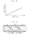
- a pair of magnetic sheets or amorphous magnetic ribbons 4-1 and 4-2 are arranged along the circumferential direction of the shaft 2 and bonded to the shaft 2 along to which a rotary torque is applied. Further, an induced magnetic anisotropy is applied in advance to the one amorphous magnetic ribbon 4-1 at an angle ⁇ to the circumferential direction, and an induced magnetic anisotropy is applied in advance to the other amorphous magnetic ribbon 4-2 at an angle -9 to the circumferential direction.
- a pair of U-shaped magnetic cores 6-1 and 6-2 formed of an oxide magnetic material is disposed in the vicinity of the shaft 2, each end face of the magnetic cores 6-1 and 6-2 is respectively placed opposite to the amorphous magnetic ribbons 4-1 and 4-2 through gaps.
- Exciting coils 8-1 and 8-2 for generating magnetic fluxes, and detecting coils 10-1 and 10-2 for detecting magnetic fluxes depend upon the magnetic permeability of the amorphous magnetic ribbons 4-1 and 4-2 which are respectively wound around the U-shaped magnetic cores 6-1 and 6-2.
- FIG 7 shows one embodiment of a circuit arrangement for the torque sensor shown in Figure 5.
- the exciting coils 8-1 and 8-2 are respectively connected to the oscillators 12-1 and 12-2 for generating the voltages of the frequency w
- the detecting coils 10-1 and 10-2 are respectively connected to the Schmitt trigger circuits 14-1 and 14-2 for converting the AC voltages generated from the detecting coils 10 into rectangular waves. Therefore, when no torque is applied to the shaft 2 at all, a phase difference does not occur between the output. voltages generated from the detecting coils 10-1 and 10-2, and so rectangular wave signals are not generated from any of the Schmitt trigger circuits 14-1, 14-2.
- a pair of U-shaped magnetic cores 6-1 and 6-2 are separately arranged.
- a core assembly 24 in which a pair of U-shaped magnetic cores 6-1 and 6-2 may be coupled to each other by a coupling bar 6-3 as shown in Figure 8A may be adopted.
- a magnetic circuit may be composed so that an exciting coil 8 is wound around the coupling bar 6-3, and so that detecting coils 10-1, 10-2, 10-3 and 10-4 are respectively wound around the legs of the magnetic cores 6-1 and 6-2, as shown in Figure 8B.
- a core assembly 30 in which core legs 26-1, 26-2 and 26-3 are coupled by a coupling core 28 as shown in Figure 9A instead of the pair of magnetic cores 6-1 and 6-2 may be employed.
- an exciting coil 8 is wound around the core legs 26-2; detecting coils 10-1 and 10-2 are respectively wound around the legs 26-1 and 26-2; and a magnetic circuit may be composed as shown in Figure 9B.
- the output characteristics shown in Figure 6 may be obtained by a voltmeter by suitably winding the exciting coils and the detecting coils around the pair of U-shaped magnetic cores 6-1 and-6-2 shown in Figure 5, by winding the coils around the core assembly 24 shown in Figure 8A, or by winding the coils around the core assembly 30 shown in Figure 9A, respectively.
- the winding directions of the detecting coils 10-1 and 10-2 wound on the core legs shown in Figure 10 may be altered to be connected in the core assembly shown in Figure 8A.
- the exciting coils 8-1 and 8-2 are wound around all the magnetic cores 6-1 and 6-2 as shown in Figure 11, and the detecting coils 10-1 and 10-2 wound by altering the winding direction or by winding in the same direction may be connected in series with each other.
- the magnetic ribbon 4 may be formed of Permalloy (Fe-Ni alloy), Sendust (Fe-AI-Si alloy), or may be preferably formed of amorphous alloy. It is further preferred that, even if a magnetic alloy is employed, its saturated magnetostriction As preferably fall within the range of the following inequality:
- the torque sensor having a magnetic ribbon formed of such a magnetic alloy has a torque with excellent linearity.
- the above-described range is based on the following consideration by the inventors. It has been discovered by the inventors that the linearity to the torque largely depends upon the saturated magnetostriction As and the induced magnetic anisotropy Ku o . In other words, according to the inventors' studies, when Ku o /3 - ⁇ s ⁇ oA>2 (Ku o : induced magnetic anisotropy; ⁇ s : saturated magnetostriction; and oA: surface stress of a thin magnetic ribbon),
- the preferred linearity can be obtained in the range of the above inequality.
- Ku o when the magnetic metal ribbon is treated in a magnetic field, the value of Ku o must be higher than predetermined value to give the ideal uniaxial magnetic anisotropy. Therefore, Ku o >1 x 10 +3 erg/cm3 .
- the thin magnetic metal strip used in the present invention may, for example, include magnetic materials of permalloy (Fe-Ni alloy), Sendust (Fe-AI-Si alloy) aram Fe-Si alloy.
- Fe-Ni alloy permalloy
- Sendust Fe-AI-Si alloy
- aram Fe-Si alloy amorphous alloy having a larger Ku o and large variable Ku 0 / ⁇ s .
- M at least one selected from the group consisting ofTi, Zr, Hf, V, Nb, Ta, Cr, Mo, W, Mn, Re, Ru, Ir, Pd, Pt, Ag, Au, Cu, Zn, Al, Ga, In, Ge, Sn, Pb, Sb, Bi, Y, and rare earth metals, where Fe is indispensable to obtain large value of induced magnetic anisotropy and to control the saturation magnetostriction. Except in the case of a ⁇ 0.05, the induced magnetic anisotropy and saturated magnetostriction are small. In case of a>0.5, the saturated magnetostriction becomes excessively large, and the linearity decreases.
- M increases the crystallizing temperature of the amorphous alloy, improves the thermal stability, can adjust the magnitude of the thermal expansion coefficient, can match the magnitude of the thermal expansion coefficient of the rotary shaft material, and is effective to obtain a torque sensor having high reliability:
- b exceeds 0.15, it becomes difficult to achieve amorphousness. Therefore, b is preferably less than 0.15.
- Si raises the crystallizing temperature.
- the above range is limited because if x exceeds 20, it becomes difficult to manufacture an amorphous alloy.
- B is indispensable to the manufacture of an amorphous alloy.
- the above range is limited because, if y is less than 4 or more than 35, it becomes difficult to manufacture an amorphous alloy.
- the preferable lower limit of Si in fact, is 1 ⁇ Si. This is because, when the content of Si increases, the productivity of the amorphous alloy is enhanced.
- a pair of amorphous alloy thin strips having a composition listed in Table 1 was produced by a single roll method. After induced magnetic anisotropies of +45° and -45° were applied to the amorphous alloy ribbons at the heat treating temperature of 300°C in a magnetic field for one hour and were left in a furnace (the magnetic field applying direction is 45° to the longitudinal direction of the ribbon with 2000 Oe), the strips were fixed to the circumferential direction of a torque transmission shaft having 55 mm in diameter. The torque was detected by a torque sensor using the magnetic ribbons shown in Figure 5, and the linearity to the torque was obtained. The obtained linearity, i.e., the degree of linearity, is listed in Table 1.
- the saturated magnetostriction ( ⁇ s ) was obtained by a strain gauge method, and the induced magnetic anisotropy (Ku) was obtained by applying a magnetic field to the longitudinal and lateral directions of the amorphous alloy, heat-treating the amorphous alloy, and was calculated from the area surrounded by two magnetizing curves in the first quadrant of the magnetization curve.
- the linearity is represented by the approximate ratio (degree of linearity (%)) between the minimum square rectilinear line of the torque value of 70 kg - m and 28 value of the minimum square rectilinear line of the output.
Claims (10)

Applications Claiming Priority (6)
| Application Number | Priority Date | Filing Date | Title |
|---|---|---|---|
| JP158717/83 | 1983-08-30 | ||
| JP58158717A JPS6050429A (ja) | 1983-08-30 | 1983-08-30 | トルクセンサ |
| JP164857/83 | 1983-09-07 | ||
| JP58164857A JPS6055682A (ja) | 1983-09-07 | 1983-09-07 | トルクセンサ |
| JP58230680A JPS60123078A (ja) | 1983-12-08 | 1983-12-08 | トルクセンサ |
| JP230680/83 | 1983-12-08 |
Publications (3)
| Publication Number | Publication Date |
|---|---|
| EP0136086A2 EP0136086A2 (de) | 1985-04-03 |
| EP0136086A3 EP0136086A3 (en) | 1986-04-02 |
| EP0136086B1 true EP0136086B1 (de) | 1988-12-28 |
Family
ID=27321389
Family Applications (1)
| Application Number | Title | Priority Date | Filing Date |
|---|---|---|---|
| EP84305819A Expired EP0136086B1 (de) | 1983-08-30 | 1984-08-24 | Nichtkontaktierender Drehmomentfühler |
Country Status (4)
| Country | Link |
|---|---|
| US (1) | US4627298A (de) |
| EP (1) | EP0136086B1 (de) |
| CA (1) | CA1225846A (de) |
| DE (1) | DE3475831D1 (de) |
Families Citing this family (55)
| Publication number | Priority date | Publication date | Assignee | Title |
|---|---|---|---|---|
| JPS6275328A (ja) * | 1985-09-30 | 1987-04-07 | Toshiba Corp | トルクセンサ |
| DE3787100T2 (de) * | 1986-01-10 | 1994-01-27 | Honda Motor Co Ltd | Sensorelement für mechanische Eigenschaft und Verfahren zu dessen Herstellung. |
| US4840073A (en) * | 1986-09-26 | 1989-06-20 | Nissan Motor Company Ltd. | Torque detecting device |
| US4760745A (en) * | 1986-12-05 | 1988-08-02 | Mag Dev Inc. | Magnetoelastic torque transducer |
| FR2622974B1 (fr) * | 1987-11-05 | 1990-06-01 | Alsthom | Dispositif de detection et de mesure des oscillations hyposynchrones d'un arbre,notamment d'un arbre d'un groupe turbo-alternateur |
| EP0480912A3 (en) * | 1987-12-28 | 1992-07-01 | Kubota Ltd. | Torque measuring device |
| JPH01187424A (ja) * | 1988-01-22 | 1989-07-26 | Toshiba Corp | トルクセンサ |
| JPH01189971A (ja) * | 1988-01-26 | 1989-07-31 | Toshiba Corp | トルクセンサ |
| US5107711A (en) * | 1988-03-04 | 1992-04-28 | Nissan Motor Company, Limited | Torque sensor |
| US5144846A (en) * | 1988-07-21 | 1992-09-08 | Sensortech, L.P. | Minimal structure magnetostrictive stress and torque sensor |
| US4858818A (en) * | 1988-08-04 | 1989-08-22 | Caterpillar Inc. | Method of bonding a magnetostrictive sheet to a shaft |
| US4899598A (en) * | 1988-08-04 | 1990-02-13 | Caterpillar Inc. | Apparatus for measuring torque applied to a shaft |
| US4918418A (en) * | 1988-08-04 | 1990-04-17 | Caterpillar Inc. | Inductive coil structure with electrical return path |
| US4909088A (en) * | 1988-08-04 | 1990-03-20 | Caterpillar Inc. | Apparatus for mounting a sensor |
| JP2800347B2 (ja) * | 1990-02-07 | 1998-09-21 | 株式会社豊田自動織機製作所 | 磁歪式トルクセンサ |
| US5351555A (en) * | 1991-07-29 | 1994-10-04 | Magnetoelastic Devices, Inc. | Circularly magnetized non-contact torque sensor and method for measuring torque using same |
| US5520059A (en) * | 1991-07-29 | 1996-05-28 | Magnetoelastic Devices, Inc. | Circularly magnetized non-contact torque sensor and method for measuring torque using same |
| US5591925A (en) * | 1991-07-29 | 1997-01-07 | Garshelis; Ivan J. | Circularly magnetized non-contact power sensor and method for measuring torque and power using same |
| JPH06216426A (ja) * | 1992-06-09 | 1994-08-05 | Nippondenso Co Ltd | 磁歪層形成方法およびそれを用いた歪センサ |
| US5631559A (en) * | 1993-03-05 | 1997-05-20 | Northeastern University | Method and apparatus for performing magnetic field measurements using magneto-optic kerr effect sensors |
| US5493220A (en) * | 1993-03-05 | 1996-02-20 | Northeastern University | Magneto-optic Kerr effect stress sensing system |
| SE501304C2 (sv) * | 1993-05-27 | 1995-01-09 | Asea Brown Boveri | Magnetoelastisk vridmomentgivare |
| SE508734C2 (sv) * | 1994-03-30 | 1998-11-02 | Asea Brown Boveri | Magnetoelastisk beröringsfri vridmomentgivare |
| US5620949A (en) * | 1995-12-13 | 1997-04-15 | The Lubrizol Corporation | Condensation products of alkylphenols and aldehydes, and derivatives thereof |
| US6145387A (en) * | 1997-10-21 | 2000-11-14 | Magna-Lastic Devices, Inc | Collarless circularly magnetized torque transducer and method for measuring torque using same |
| JP2001133337A (ja) * | 1999-11-01 | 2001-05-18 | Honda Motor Co Ltd | 磁歪式トルクセンサ及び磁歪式トルクセンサを搭載した電動パワーステアリング装置 |
| US6494102B2 (en) * | 2001-01-12 | 2002-12-17 | Trw Inc. | Magnetostrictive stress sensor |
| GB0204213D0 (en) * | 2002-02-22 | 2002-04-10 | Fast Technology Ag | Pulsed torque measurement |
| JP3898610B2 (ja) * | 2002-09-18 | 2007-03-28 | 本田技研工業株式会社 | トルクセンサ |
| US6871553B2 (en) * | 2003-03-28 | 2005-03-29 | Delphi Technologies, Inc. | Integrating fluxgate for magnetostrictive torque sensors |
| US7055399B2 (en) * | 2003-05-01 | 2006-06-06 | Visteon Global Technologies, Inc. | Unshunted collarless torsion shaft for electronic power-assisted steering systems |
| EP1477788B1 (de) * | 2003-05-12 | 2006-04-26 | HONDA MOTOR CO., Ltd. | Verfahren zum Aufbringen einer magnetostriktiven Beschichtung |
| US7469604B2 (en) | 2005-10-21 | 2008-12-30 | Stoneridge Control Devices, Inc. | Sensor system including a magnetized shaft |
| US7363827B2 (en) * | 2005-10-21 | 2008-04-29 | Stoneridge Control Devices, Inc. | Torque sensor system including an elliptically magnetized shaft |
| US7423411B2 (en) * | 2006-05-05 | 2008-09-09 | General Electric Company | Resistive torsional mode damping system and method |
| JP5091555B2 (ja) * | 2007-06-22 | 2012-12-05 | 本田技研工業株式会社 | 磁歪式トルクセンサおよび電動パワーステアリング装置 |
| KR101643182B1 (ko) | 2008-03-14 | 2016-07-27 | 마그나-라스틱 디바이시스, 인코포레이티드 | 주위 자기장 차단 자기탄성 토크 센서 |
| US8079274B2 (en) * | 2008-05-22 | 2011-12-20 | IEM Corp. | Rotational component torque measurement and monitoring system |
| US7886863B2 (en) * | 2009-02-12 | 2011-02-15 | American Axle & Manufacturing, Inc. | Driveshaft assembly with torque sensor |
| US8001849B2 (en) * | 2009-03-28 | 2011-08-23 | Wensheng Weng | Self-compensating magnetoelastic torque sensor system |
| CN101871827A (zh) * | 2010-06-04 | 2010-10-27 | 重庆大学 | 一种环型空间阵列扭矩传感器的读数头 |
| EP2397829B1 (de) | 2010-06-21 | 2016-04-27 | PolyResearch AG | Dynamischer Signal-Drehmomentsensor. |
| DE102011075391A1 (de) * | 2011-05-06 | 2013-02-14 | Siemens Aktiengesellschaft | Magnetoelastischer Drehmomentsensor |
| EP2602595B1 (de) * | 2011-12-08 | 2016-03-02 | PolyResearch AG | Aktiver mechanischer Kraftsensor |
| US8844375B2 (en) | 2012-12-19 | 2014-09-30 | General Electric Company | Mechanical force components sensing system and an associated method thereof for a magnetically encoded device |
| US10168236B2 (en) * | 2013-12-03 | 2019-01-01 | Safran Aircraft Engines | Torque-measurement device for a turbomachine shaft |
| US10094720B2 (en) | 2014-04-10 | 2018-10-09 | General Electric Company | System and method of magnetic shielding for sensors |
| US9429488B2 (en) * | 2014-04-10 | 2016-08-30 | General Electric Company | System and method of magnetic shielding for sensors |
| EP3051265B1 (de) * | 2015-01-29 | 2017-10-11 | Torque and More (TAM) GmbH | Kraftmessvorrichtung |
| EP3064919A1 (de) * | 2015-03-04 | 2016-09-07 | Torque and More (TAM) GmbH | Magnetfeldphasenverzögerungsmessung |
| DE102015122154B4 (de) * | 2015-12-17 | 2018-09-27 | Methode Electronics Malta Ltd. | Vorrichtung zur Feststellung externer magnetischer Streufelder auf einen Magnetfeldsensor |
| US20170234755A1 (en) * | 2016-02-17 | 2017-08-17 | Ford Global Technologies, Llc | Variability Compensation For Paired Shafts and Sensors |
| DE102016122172B4 (de) | 2016-07-25 | 2018-02-01 | Trafag Ag | Sensorkopf für einen Kraft- oder Drehmomentsensor |
| DE102018131737A1 (de) | 2018-12-11 | 2020-06-18 | ACPS Automotive GmbH | Kupplungseinheit |
| CN114112138A (zh) * | 2020-08-26 | 2022-03-01 | 东北林业大学 | 一种可变匝数的磁聚焦式传感器及转速、扭矩计算方法 |
Family Cites Families (6)
| Publication number | Priority date | Publication date | Assignee | Title |
|---|---|---|---|---|
| US3906361A (en) * | 1973-09-26 | 1975-09-16 | Us Air Force | Digital phase measuring system |
| DE2939566A1 (de) * | 1979-09-29 | 1981-04-09 | Zahnradfabrik Friedrichshafen Ag, 7990 Friedrichshafen | Magnetostriktives messverfahren, insbesondere zur drehmomentmessung an wellen |
| US4414855A (en) * | 1981-06-01 | 1983-11-15 | Aisin Seiki Kabushiki Kaisha | Torque sensor |
| CA1214660A (en) * | 1982-09-30 | 1986-12-02 | Koichiro Inomata | Torque sensor and method for manufacturing the same |
| JPS5961732A (ja) * | 1983-06-06 | 1984-04-09 | Toshiba Corp | トルクセンサの製造方法 |
| US4506554A (en) * | 1983-06-07 | 1985-03-26 | Asea Aktiebolag | Magnetoelastic torque transducer |
-
1984
- 1984-08-24 EP EP84305819A patent/EP0136086B1/de not_active Expired
- 1984-08-24 US US06/643,703 patent/US4627298A/en not_active Expired - Lifetime
- 1984-08-24 DE DE8484305819T patent/DE3475831D1/de not_active Expired
- 1984-08-29 CA CA000462058A patent/CA1225846A/en not_active Expired
Also Published As
| Publication number | Publication date |
|---|---|
| US4627298A (en) | 1986-12-09 |
| DE3475831D1 (en) | 1989-02-02 |
| EP0136086A3 (en) | 1986-04-02 |
| EP0136086A2 (de) | 1985-04-03 |
| CA1225846A (en) | 1987-08-25 |
Similar Documents
| Publication | Publication Date | Title |
|---|---|---|
| EP0136086B1 (de) | Nichtkontaktierender Drehmomentfühler | |
| US5351555A (en) | Circularly magnetized non-contact torque sensor and method for measuring torque using same | |
| USRE34039E (en) | Torque sensor for detecting a shaft torque and an electric machine in which the torque sensor is mounted | |
| US4823617A (en) | Torque sensor | |
| US5142227A (en) | Method and apparatus for measuring strain within a ferromagnetic material by sensing change in coercive field | |
| US5323659A (en) | Multifunctional torque sensor | |
| US4762008A (en) | Torque detecting apparatus | |
| US4631796A (en) | Torque sensor and method for manufacturing the same | |
| EP0185406B1 (de) | Magnetkopf mit Kernteilen aus ferromagnetischem amorphem Metall | |
| JP3494018B2 (ja) | 磁界検出センサ | |
| US4590807A (en) | Torque sensor of noncontact type | |
| US4720676A (en) | Magnetomechanical transducer utilizing resonant frequency shifts to measure pressure in response to displacement of a pressure sensitive device | |
| US4985108A (en) | Method of mounting a mechanical quantity sensor element | |
| JPH0610327B2 (ja) | トルクセンサ | |
| JPS59226882A (ja) | 磁気信号変換素子 | |
| US4710709A (en) | Magnetomechanical transducers utilizing resonant frequency shifts to measure displacement of an object | |
| JPS59180338A (ja) | トルクセンサ | |
| JPS60123078A (ja) | トルクセンサ | |
| JPH0559374B2 (de) | ||
| JPH0763627A (ja) | 力学量センサ | |
| JPH0222524A (ja) | アモルファス応力センサ | |
| JPH055660A (ja) | トルクセンサおよびその製造法 | |
| JPH08184657A (ja) | 地磁気センサ | |
| JPS63118627A (ja) | トルクセンサ | |
| JPS6182126A (ja) | トルクセンサ |
Legal Events
| Date | Code | Title | Description |
|---|---|---|---|
| PUAI | Public reference made under article 153(3) epc to a published international application that has entered the european phase |
Free format text: ORIGINAL CODE: 0009012 |
|
| 17P | Request for examination filed |
Effective date: 19840910 |
|
| AK | Designated contracting states |
Designated state(s): DE FR GB IT |
|
| PUAL | Search report despatched |
Free format text: ORIGINAL CODE: 0009013 |
|
| AK | Designated contracting states |
Kind code of ref document: A3 Designated state(s): DE FR GB IT |
|
| 17Q | First examination report despatched |
Effective date: 19870619 |
|
| GRAA | (expected) grant |
Free format text: ORIGINAL CODE: 0009210 |
|
| AK | Designated contracting states |
Kind code of ref document: B1 Designated state(s): DE FR GB IT |
|
| ITF | It: translation for a ep patent filed |
Owner name: JACOBACCI & PERANI S.P.A. |
|
| REF | Corresponds to: |
Ref document number: 3475831 Country of ref document: DE Date of ref document: 19890202 |
|
| ET | Fr: translation filed | ||
| PLBE | No opposition filed within time limit |
Free format text: ORIGINAL CODE: 0009261 |
|
| STAA | Information on the status of an ep patent application or granted ep patent |
Free format text: STATUS: NO OPPOSITION FILED WITHIN TIME LIMIT |
|
| 26N | No opposition filed | ||
| ITTA | It: last paid annual fee | ||
| REG | Reference to a national code |
Ref country code: GB Ref legal event code: 746 Effective date: 19981026 |
|
| REG | Reference to a national code |
Ref country code: FR Ref legal event code: D6 |
|
| PGFP | Annual fee paid to national office [announced via postgrant information from national office to epo] |
Ref country code: FR Payment date: 20010810 Year of fee payment: 18 |
|
| PGFP | Annual fee paid to national office [announced via postgrant information from national office to epo] |
Ref country code: DE Payment date: 20010820 Year of fee payment: 18 |
|
| PGFP | Annual fee paid to national office [announced via postgrant information from national office to epo] |
Ref country code: GB Payment date: 20010822 Year of fee payment: 18 |
|
| REG | Reference to a national code |
Ref country code: GB Ref legal event code: IF02 |
|
| PG25 | Lapsed in a contracting state [announced via postgrant information from national office to epo] |
Ref country code: GB Free format text: LAPSE BECAUSE OF NON-PAYMENT OF DUE FEES Effective date: 20020824 |
|
| PG25 | Lapsed in a contracting state [announced via postgrant information from national office to epo] |
Ref country code: DE Free format text: LAPSE BECAUSE OF NON-PAYMENT OF DUE FEES Effective date: 20030301 |
|
| GBPC | Gb: european patent ceased through non-payment of renewal fee |
Effective date: 20020824 |
|
| PG25 | Lapsed in a contracting state [announced via postgrant information from national office to epo] |
Ref country code: FR Free format text: LAPSE BECAUSE OF NON-PAYMENT OF DUE FEES Effective date: 20030430 |
|
| REG | Reference to a national code |
Ref country code: FR Ref legal event code: ST |