EP0134883A2 - Dispositif pour mettre au point un objectif - Google Patents
Dispositif pour mettre au point un objectif Download PDFInfo
- Publication number
- EP0134883A2 EP0134883A2 EP84103806A EP84103806A EP0134883A2 EP 0134883 A2 EP0134883 A2 EP 0134883A2 EP 84103806 A EP84103806 A EP 84103806A EP 84103806 A EP84103806 A EP 84103806A EP 0134883 A2 EP0134883 A2 EP 0134883A2
- Authority
- EP
- European Patent Office
- Prior art keywords
- wheel
- lens
- following
- adjusting wheel
- sleeve
- Prior art date
- Legal status (The legal status is an assumption and is not a legal conclusion. Google has not performed a legal analysis and makes no representation as to the accuracy of the status listed.)
- Withdrawn
Links
Images
Classifications
-
- G—PHYSICS
- G02—OPTICS
- G02B—OPTICAL ELEMENTS, SYSTEMS OR APPARATUS
- G02B7/00—Mountings, adjusting means, or light-tight connections, for optical elements
- G02B7/02—Mountings, adjusting means, or light-tight connections, for optical elements for lenses
- G02B7/04—Mountings, adjusting means, or light-tight connections, for optical elements for lenses with mechanism for focusing or varying magnification
-
- Y—GENERAL TAGGING OF NEW TECHNOLOGICAL DEVELOPMENTS; GENERAL TAGGING OF CROSS-SECTIONAL TECHNOLOGIES SPANNING OVER SEVERAL SECTIONS OF THE IPC; TECHNICAL SUBJECTS COVERED BY FORMER USPC CROSS-REFERENCE ART COLLECTIONS [XRACs] AND DIGESTS
- Y10—TECHNICAL SUBJECTS COVERED BY FORMER USPC
- Y10T—TECHNICAL SUBJECTS COVERED BY FORMER US CLASSIFICATION
- Y10T74/00—Machine element or mechanism
- Y10T74/18—Mechanical movements
- Y10T74/18056—Rotary to or from reciprocating or oscillating
- Y10T74/18296—Cam and slide
- Y10T74/18304—Axial cam
-
- Y—GENERAL TAGGING OF NEW TECHNOLOGICAL DEVELOPMENTS; GENERAL TAGGING OF CROSS-SECTIONAL TECHNOLOGIES SPANNING OVER SEVERAL SECTIONS OF THE IPC; TECHNICAL SUBJECTS COVERED BY FORMER USPC CROSS-REFERENCE ART COLLECTIONS [XRACs] AND DIGESTS
- Y10—TECHNICAL SUBJECTS COVERED BY FORMER USPC
- Y10T—TECHNICAL SUBJECTS COVERED BY FORMER US CLASSIFICATION
- Y10T74/00—Machine element or mechanism
- Y10T74/21—Elements
- Y10T74/2101—Cams
- Y10T74/2107—Follower
Definitions
- the invention relates to a device for focusing a lens, which is arranged axially displaceably in a lens sleeve supported on a film stage.
- Such devices are used, for example, in microfilm readers and are therefore generally known.
- the distance between the microfilm and the lens remains constant when the film stage is shifted, provided the thickness of the upper transparent plate of the film stage is constant and the microfilm lies flat in the film stage.
- the thickness fluctuations of the upper plate are seen over their surface such that the lens often has to be refocused when the film stage is moved.
- Such refocusing is also necessary if the film stage is not exactly aligned in a plane perpendicular to the lens.
- the lens sleeve moves up and down with the eye, perceptibly in the vertical direction.
- the required mobility of the lens sleeve in the vertical direction requires that movable transmission means are provided between the adjusting wheel for focusing the lens and the lens, which allow these necessary strokes of the lens sleeve in the vertical direction.
- the known device for focusing a lens is relatively complex.
- the result of this is that in microfilm readers with two lenses of different focal lengths, usually only one focusing device is provided, by means of which the two lenses are always adjusted in parallel with one another. If you switch from one lens to another, you will need to refocus.
- the invention has for its object to develop a device of the type mentioned, which allows axial movement of the lens sleeve with the least possible structural effort.
- the main advantage of the device according to the invention lies in its extremely simple construction. Instead of providing deformable intermediate links, the inventor came up with the idea of making the adjusting wheel deformable in the axial direction itself. This makes the device very simple and functionally advantageous overall. Due to the lack of intermediate links, focusing can take place very directly and without play, so that sensitive adjustment is possible.
- the setting wheel is particularly simple if it is formed from an outer wheel rim which is variable in thickness along its circumference and a thin-walled wheel disk holding the wheel.
- the required axial deformability of the adjusting wheel can be generated in that the wheel disc is designed as an elastic membrane.
- the adjusting wheel engages in a groove of the objective sleeve with a radially outwardly directed, circumferential web.
- the setting wheel then inevitably moves down with the lens sleeve when it moves down with the surface of the film stage. Without this bridge, it could happen under unfavorable conditions that the relatively heavy lens sleeve moves downward and the lens remains in its position by means of the adjusting wheel.
- the adjusting wheel would hold the lens, so that the focus would be lost.
- the setting wheel If the setting wheel is elastically biased towards the film stage, then it acts as a downhaul for the lens sleeve. It ensures that the lens sleeve always remains in contact with the film stage. In such a case, the setting wheel acts like a plate spring.
- the measure specified in claim 8 ensures that the lens is adjusted uniformly in one direction when the adjusting wheel is rotated up to 180 degrees.
- the lens sleeve must be able to follow the film stage which can be moved obliquely to the lens so that the focusing is not lost.
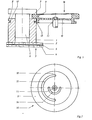
- FIG. 1 shows a lens sleeve 1, which is sliding on an upper transparent plate 2 of a film stage 3.
- the film stage 3 also has a lower, transparent plate 4, so that a microfiche 5 can be placed between the plates 2, 3.
- a lens 6 is guided axially displaceably in the lens sleeve 1, through which film images of the microfiches 5 can be projected enlarged onto the focusing screen (not shown) of the microfilm reading device.
- This lens 6 engages with a collar 7 over the upper end face 8 of the lens sleeve 1.
- an adjusting wheel 16 engages with a wheel rim 9.
- This adjusting wheel 16 consists of a relatively thin-walled wheel disc 10 and the wheel rim 9.
- the wheel rim 9 is not uniformly thick seen over the setting wheel circumference, rather its thickness increases uniformly over 180 degrees.
- the adjusting wheel 16 is rotatably mounted in the center by means of an axis 11 on the lens carrier of the microfilm reading device, not shown. If you turn the adjusting wheel 16, depending on the direction of rotation, a region of less or greater thickness of the wheel rim 9 enters the space between the collar 7 and the end face 8 and moves the objective 6 relative to the objective sleeve 1.
- FIG. 1 further shows that the lens sleeve 1 near its adjusting wheel 16 has a circumferential groove 12 into which an outwardly directed, circumferential web 13 of the adjusting wheel 16 engages.
- the relatively heavy objective sleeve 1 inevitably bends the adjusting wheel 16, provided that the objective sleeve 1 moves downward, for example as a result of an oblique course of the film stage guide. Without the web in connection with the groove 12, it could happen that the adjusting wheel 16 holds the lens 6 back when the lens sleeve 1 moves downward, so that there is a relative movement between the lens and the lens sleeve.
- the axial deformability of the adjusting wheel 16, which is necessary to enable axial movement of the objective sleeve 1, is brought about by the fact that the wheel disk 10 is relatively thin-walled and that, as FIG. 2 shows, two arcuate recesses 14, 15 in the wheel disk 10 or slots are provided.
- the recesses 14, 15 are semicircular and have different diameters. Instead of the two recesses 14, 15, a single spiral recess can also be provided. It would also be conceivable to connect the wheel rim to a hub area of the adjusting wheel 16 by means of spokes.
- the end faces of the wheel rim 9 are of spherical design.
Landscapes
- Physics & Mathematics (AREA)
- General Physics & Mathematics (AREA)
- Optics & Photonics (AREA)
- Lens Barrels (AREA)
- Variable Magnification In Projection-Type Copying Machines (AREA)
- Telescopes (AREA)
Applications Claiming Priority (2)
| Application Number | Priority Date | Filing Date | Title |
|---|---|---|---|
| DE19833329003 DE3329003A1 (de) | 1983-08-11 | 1983-08-11 | Vorrichtung zum fokussieren eines objektivs |
| DE3329003 | 1983-08-11 |
Publications (2)
| Publication Number | Publication Date |
|---|---|
| EP0134883A2 true EP0134883A2 (fr) | 1985-03-27 |
| EP0134883A3 EP0134883A3 (fr) | 1987-09-09 |
Family
ID=6206309
Family Applications (1)
| Application Number | Title | Priority Date | Filing Date |
|---|---|---|---|
| EP84103806A Withdrawn EP0134883A3 (fr) | 1983-08-11 | 1984-04-06 | Dispositif pour mettre au point un objectif |
Country Status (4)
| Country | Link |
|---|---|
| US (1) | US4583823A (fr) |
| EP (1) | EP0134883A3 (fr) |
| JP (1) | JPS6043618A (fr) |
| DE (1) | DE3329003A1 (fr) |
Families Citing this family (4)
| Publication number | Priority date | Publication date | Assignee | Title |
|---|---|---|---|---|
| JPS5688231A (en) * | 1979-12-20 | 1981-07-17 | Nec Corp | Color picture tube and its manufacture |
| DE3439254A1 (de) * | 1984-10-26 | 1986-04-30 | MAP Mikrofilm Apparatebau Dr. Poehler GmbH & Co KG, 6352 Ober-Mörlen | Objektivhalterung |
| JP2687565B2 (ja) * | 1989-03-30 | 1997-12-08 | 三菱電機株式会社 | カラー受像管用露光装置 |
| CN109814320B (zh) * | 2019-03-07 | 2021-02-05 | 北京空间机电研究所 | 一种基于盘形凸轮的调焦机构 |
Family Cites Families (4)
| Publication number | Priority date | Publication date | Assignee | Title |
|---|---|---|---|---|
| US2164847A (en) * | 1937-07-02 | 1939-07-04 | Bausch & Lomb | Projector |
| US3254585A (en) * | 1964-02-10 | 1966-06-07 | Graflex Inc | Focusing mechanism for photographic cameras |
| US3814514A (en) * | 1972-09-06 | 1974-06-04 | Xerox Corp | Microform projection and viewer apparatus |
| DE3050314C2 (de) * | 1980-08-23 | 1983-07-28 | Fa. Ed. Liesegang, 4000 Düsseldorf | Formatblende mit Blendenaufnahme in einem Projektor |
-
1983
- 1983-08-11 DE DE19833329003 patent/DE3329003A1/de not_active Withdrawn
-
1984
- 1984-04-06 EP EP84103806A patent/EP0134883A3/fr not_active Withdrawn
- 1984-06-07 US US06/618,137 patent/US4583823A/en not_active Expired - Fee Related
- 1984-07-09 JP JP59140764A patent/JPS6043618A/ja active Pending
Also Published As
| Publication number | Publication date |
|---|---|
| JPS6043618A (ja) | 1985-03-08 |
| DE3329003A1 (de) | 1985-02-28 |
| US4583823A (en) | 1986-04-22 |
| EP0134883A3 (fr) | 1987-09-09 |
Similar Documents
| Publication | Publication Date | Title |
|---|---|---|
| DE3622843C2 (fr) | ||
| DE2512424C2 (de) | Verstelleinrichtung für photographische, kinematographische oder reprographische Objektive | |
| DE2163993C2 (de) | Vorrichtung zur Auswertung von Mikrofilmstreifen | |
| CH639194A5 (de) | Vorrichtung zum beruehrungslosen messen der konturform von gegenstaenden. | |
| DE2749324A1 (de) | Fokussiervorrichtung fuer optische geraete, insbesondere fuer kameras | |
| DD201826A5 (de) | Optisches system zur erzeugung eines kollimierten lichtbuendels | |
| DE2715646A1 (de) | Verstelleinrichtung zur fokussierung von objektiven | |
| DE10340924A1 (de) | Identifikationseinrichtung | |
| EP0134883A2 (fr) | Dispositif pour mettre au point un objectif | |
| DE4013743C2 (fr) | ||
| DE68911054T2 (de) | Vorrichtung zum Abtasten mittels Strahlung. | |
| DE2553403A1 (de) | Vorrichtung zum feststellen von unebenheiten einer gekruemmten flaeche | |
| DE2923892C2 (fr) | ||
| DE69222011T2 (de) | Röntgenanalysegerät | |
| EP2511852A1 (fr) | Dispositif d'éclairage pour un lecteur de code à barres basé sur un appareil de prise de vue | |
| DE19918086B4 (de) | Einstellscheibe für eine Kamera | |
| EP0333637A2 (fr) | Macro-objectif avec une bague de mise au point montée rotativement sur le boîtier de l'objectif | |
| DE1639346B2 (de) | Vorrichtung zum Verstellen des Objektes quer zur Strahlennchtung in einem Korpuskularstrahlengerat | |
| DE2226137B2 (de) | Mikroskop | |
| EP0179284B1 (fr) | Monture d'objectif | |
| DE3215595C2 (de) | Fokussiereinrichtung | |
| DE421610C (de) | Objektivrevolver fuer kinematographische Aufnahmeapparate | |
| DE2655020A1 (de) | Filterhalter, insbesondere fuer optische verlauffilter | |
| DE1961630A1 (de) | Fokussierbares Kameraobjektiv | |
| DE2442795A1 (de) | Automatische fokussierungsvorrichtung |
Legal Events
| Date | Code | Title | Description |
|---|---|---|---|
| PUAI | Public reference made under article 153(3) epc to a published international application that has entered the european phase |
Free format text: ORIGINAL CODE: 0009012 |
|
| AK | Designated contracting states |
Designated state(s): AT BE CH DE FR GB IT LI LU NL SE |
|
| PUAL | Search report despatched |
Free format text: ORIGINAL CODE: 0009013 |
|
| AK | Designated contracting states |
Kind code of ref document: A3 Designated state(s): AT BE CH DE FR GB IT LI LU NL SE |
|
| STAA | Information on the status of an ep patent application or granted ep patent |
Free format text: STATUS: THE APPLICATION IS DEEMED TO BE WITHDRAWN |
|
| 18D | Application deemed to be withdrawn |
Effective date: 19880510 |
|
| RIN1 | Information on inventor provided before grant (corrected) |
Inventor name: WALCZAK, ANDRZEJ, DIPL.-ING. |