EP0134883A2 - Device for focusing an objective - Google Patents
Device for focusing an objective Download PDFInfo
- Publication number
- EP0134883A2 EP0134883A2 EP84103806A EP84103806A EP0134883A2 EP 0134883 A2 EP0134883 A2 EP 0134883A2 EP 84103806 A EP84103806 A EP 84103806A EP 84103806 A EP84103806 A EP 84103806A EP 0134883 A2 EP0134883 A2 EP 0134883A2
- Authority
- EP
- European Patent Office
- Prior art keywords
- wheel
- lens
- following
- adjusting wheel
- sleeve
- Prior art date
- Legal status (The legal status is an assumption and is not a legal conclusion. Google has not performed a legal analysis and makes no representation as to the accuracy of the status listed.)
- Withdrawn
Links
Images
Classifications
-
- G—PHYSICS
- G02—OPTICS
- G02B—OPTICAL ELEMENTS, SYSTEMS OR APPARATUS
- G02B7/00—Mountings, adjusting means, or light-tight connections, for optical elements
- G02B7/02—Mountings, adjusting means, or light-tight connections, for optical elements for lenses
- G02B7/04—Mountings, adjusting means, or light-tight connections, for optical elements for lenses with mechanism for focusing or varying magnification
-
- Y—GENERAL TAGGING OF NEW TECHNOLOGICAL DEVELOPMENTS; GENERAL TAGGING OF CROSS-SECTIONAL TECHNOLOGIES SPANNING OVER SEVERAL SECTIONS OF THE IPC; TECHNICAL SUBJECTS COVERED BY FORMER USPC CROSS-REFERENCE ART COLLECTIONS [XRACs] AND DIGESTS
- Y10—TECHNICAL SUBJECTS COVERED BY FORMER USPC
- Y10T—TECHNICAL SUBJECTS COVERED BY FORMER US CLASSIFICATION
- Y10T74/00—Machine element or mechanism
- Y10T74/18—Mechanical movements
- Y10T74/18056—Rotary to or from reciprocating or oscillating
- Y10T74/18296—Cam and slide
- Y10T74/18304—Axial cam
-
- Y—GENERAL TAGGING OF NEW TECHNOLOGICAL DEVELOPMENTS; GENERAL TAGGING OF CROSS-SECTIONAL TECHNOLOGIES SPANNING OVER SEVERAL SECTIONS OF THE IPC; TECHNICAL SUBJECTS COVERED BY FORMER USPC CROSS-REFERENCE ART COLLECTIONS [XRACs] AND DIGESTS
- Y10—TECHNICAL SUBJECTS COVERED BY FORMER USPC
- Y10T—TECHNICAL SUBJECTS COVERED BY FORMER US CLASSIFICATION
- Y10T74/00—Machine element or mechanism
- Y10T74/21—Elements
- Y10T74/2101—Cams
- Y10T74/2107—Follower
Definitions
- the invention relates to a device for focusing a lens, which is arranged axially displaceably in a lens sleeve supported on a film stage.
- Such devices are used, for example, in microfilm readers and are therefore generally known.
- the distance between the microfilm and the lens remains constant when the film stage is shifted, provided the thickness of the upper transparent plate of the film stage is constant and the microfilm lies flat in the film stage.
- the thickness fluctuations of the upper plate are seen over their surface such that the lens often has to be refocused when the film stage is moved.
- Such refocusing is also necessary if the film stage is not exactly aligned in a plane perpendicular to the lens.
- the lens sleeve moves up and down with the eye, perceptibly in the vertical direction.
- the required mobility of the lens sleeve in the vertical direction requires that movable transmission means are provided between the adjusting wheel for focusing the lens and the lens, which allow these necessary strokes of the lens sleeve in the vertical direction.
- the known device for focusing a lens is relatively complex.
- the result of this is that in microfilm readers with two lenses of different focal lengths, usually only one focusing device is provided, by means of which the two lenses are always adjusted in parallel with one another. If you switch from one lens to another, you will need to refocus.
- the invention has for its object to develop a device of the type mentioned, which allows axial movement of the lens sleeve with the least possible structural effort.
- the main advantage of the device according to the invention lies in its extremely simple construction. Instead of providing deformable intermediate links, the inventor came up with the idea of making the adjusting wheel deformable in the axial direction itself. This makes the device very simple and functionally advantageous overall. Due to the lack of intermediate links, focusing can take place very directly and without play, so that sensitive adjustment is possible.
- the setting wheel is particularly simple if it is formed from an outer wheel rim which is variable in thickness along its circumference and a thin-walled wheel disk holding the wheel.
- the required axial deformability of the adjusting wheel can be generated in that the wheel disc is designed as an elastic membrane.
- the adjusting wheel engages in a groove of the objective sleeve with a radially outwardly directed, circumferential web.
- the setting wheel then inevitably moves down with the lens sleeve when it moves down with the surface of the film stage. Without this bridge, it could happen under unfavorable conditions that the relatively heavy lens sleeve moves downward and the lens remains in its position by means of the adjusting wheel.
- the adjusting wheel would hold the lens, so that the focus would be lost.
- the setting wheel If the setting wheel is elastically biased towards the film stage, then it acts as a downhaul for the lens sleeve. It ensures that the lens sleeve always remains in contact with the film stage. In such a case, the setting wheel acts like a plate spring.
- the measure specified in claim 8 ensures that the lens is adjusted uniformly in one direction when the adjusting wheel is rotated up to 180 degrees.
- the lens sleeve must be able to follow the film stage which can be moved obliquely to the lens so that the focusing is not lost.
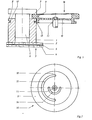
- FIG. 1 shows a lens sleeve 1, which is sliding on an upper transparent plate 2 of a film stage 3.
- the film stage 3 also has a lower, transparent plate 4, so that a microfiche 5 can be placed between the plates 2, 3.
- a lens 6 is guided axially displaceably in the lens sleeve 1, through which film images of the microfiches 5 can be projected enlarged onto the focusing screen (not shown) of the microfilm reading device.
- This lens 6 engages with a collar 7 over the upper end face 8 of the lens sleeve 1.
- an adjusting wheel 16 engages with a wheel rim 9.
- This adjusting wheel 16 consists of a relatively thin-walled wheel disc 10 and the wheel rim 9.
- the wheel rim 9 is not uniformly thick seen over the setting wheel circumference, rather its thickness increases uniformly over 180 degrees.
- the adjusting wheel 16 is rotatably mounted in the center by means of an axis 11 on the lens carrier of the microfilm reading device, not shown. If you turn the adjusting wheel 16, depending on the direction of rotation, a region of less or greater thickness of the wheel rim 9 enters the space between the collar 7 and the end face 8 and moves the objective 6 relative to the objective sleeve 1.
- FIG. 1 further shows that the lens sleeve 1 near its adjusting wheel 16 has a circumferential groove 12 into which an outwardly directed, circumferential web 13 of the adjusting wheel 16 engages.
- the relatively heavy objective sleeve 1 inevitably bends the adjusting wheel 16, provided that the objective sleeve 1 moves downward, for example as a result of an oblique course of the film stage guide. Without the web in connection with the groove 12, it could happen that the adjusting wheel 16 holds the lens 6 back when the lens sleeve 1 moves downward, so that there is a relative movement between the lens and the lens sleeve.
- the axial deformability of the adjusting wheel 16, which is necessary to enable axial movement of the objective sleeve 1, is brought about by the fact that the wheel disk 10 is relatively thin-walled and that, as FIG. 2 shows, two arcuate recesses 14, 15 in the wheel disk 10 or slots are provided.
- the recesses 14, 15 are semicircular and have different diameters. Instead of the two recesses 14, 15, a single spiral recess can also be provided. It would also be conceivable to connect the wheel rim to a hub area of the adjusting wheel 16 by means of spokes.
- the end faces of the wheel rim 9 are of spherical design.
Landscapes
- Physics & Mathematics (AREA)
- General Physics & Mathematics (AREA)
- Optics & Photonics (AREA)
- Lens Barrels (AREA)
- Telescopes (AREA)
- Variable Magnification In Projection-Type Copying Machines (AREA)
Abstract
Bei einer Vorrichtung zum Fokussieren eines Objektivs (6), welches axial verschieblich in einer gleitend auf einer Filmbühne (3) abgestützten Objektivhülse (1) angeordnet ist, greift ein Stellrad (16) mit einem Radkranz (9) zwischen einem Bund (7) des Objektivs (6) und einer oberen Stirnfläche (8) der Objektivhülse (1 ). Der Radkranz nimmt in seiner Dicke über seinen halben Umfang gesehen, gleichförmig zu. Dadurch kommt es bei Verdrehung des Stellrades (16) zu einer Relativbewegung zwischen Objektiv (6) und Objektivhülse (1). Das Stellrad (16) ist in axialer Richtung verformbar. Dies erlaubt es, trotz fester Lagerung des Stellrades (16) der Objektivhülse (1) in begrenztem Maße, sich axial zu bewegen und damit dem Verlauf der oberen Platte (2) der Filmbühne (3) zu folgen.
Description
Die Erfindung bezieht sich auf eine Vorrichtung zum Fokussieren eines Objektivs, welches axial verschieblich in einer gleitend auf einer Filmbühne abgestützten Objektivhülse angeordnet ist. Solche Vorrichtungen sind zum Beispiel in Mikrofilm-Lesegeräten gebräuchlich und daher allgemein bekannt.The invention relates to a device for focusing a lens, which is arranged axially displaceably in a lens sleeve supported on a film stage. Such devices are used, for example, in microfilm readers and are therefore generally known.
Durch die gleitende Abstützung der Objektivhülse auf der Filmbühne bleibt der Abstand zwischen Mikrofilm und Objektiv bei Verschiebung der Filmbühne konstant, sofern die Dicke der oberen durchsichtigen Platte der Filmbühne konstant ist und der Mikrofilm plan in der Filmbühne liegt. In der Praxis sind die Dickenschwankungen der oberen Platte über ihre Fläche gesehen derart, daß bei Verschiebung der Filmbühne häufig das Objektiv nachfokussiert werden muß. Ein solches Nachfokussieren ist auch erforderlich, wenn die Filmbühne nicht genau in einer rechtwinklig zum Objektiv verlaufenden Ebene ausgerichtet ist. In einem solchen Fall bewegt sich bei Verschiebung der Filmbühne die Objektivhülse mit dem Auge wahrnehmbar in vertikaler Richtung auf und ab. Die erforderliche Beweglichkeit der Objektivhülse in vertikaler-Richtung bedingt es, daß zwischen dem Stellrad zum Fokussieren des Objektivs und dem Objektiv bewegliche übertragungsmittel-vorgesehen werden, die diese notwendigen Hübe der Objektivhülse in vertikaler Richtung zulassen.Due to the sliding support of the lens sleeve on the film stage, the distance between the microfilm and the lens remains constant when the film stage is shifted, provided the thickness of the upper transparent plate of the film stage is constant and the microfilm lies flat in the film stage. In practice, the thickness fluctuations of the upper plate are seen over their surface such that the lens often has to be refocused when the film stage is moved. Such refocusing is also necessary if the film stage is not exactly aligned in a plane perpendicular to the lens. In such a case, when the film stage is shifted, the lens sleeve moves up and down with the eye, perceptibly in the vertical direction. The required mobility of the lens sleeve in the vertical direction requires that movable transmission means are provided between the adjusting wheel for focusing the lens and the lens, which allow these necessary strokes of the lens sleeve in the vertical direction.
Durch die Zwischenschaltung beweglicher übertragungsglieder wird die bekannte Vorrichtung zum Fokussieren eines Objektivs relativ aufwendig. Das führt dazu, daß man bei Mikrofilm-Lesegeräten mit zwei Objektiven verschiedener Brennweite üblicherweise nur eine Fokussiereinrichtung vorsieht, durch die beide Objektive parallel zueinander stets gleichzeitig verstellt werden. Wechselt man von einem zum anderen Objektiv, dann ist zwangsläufig ein Nachfokussieren erforderlich.By interposing movable transmission elements, the known device for focusing a lens is relatively complex. The result of this is that in microfilm readers with two lenses of different focal lengths, usually only one focusing device is provided, by means of which the two lenses are always adjusted in parallel with one another. If you switch from one lens to another, you will need to refocus.
Der Erfindung liegt die Aufgabe zugrunde, eine Vorrichtung der eingangs genannten Art zu entwickeln, welche mit möglichst geringem baulichen Aufwand eine axiale Bewegung der Objektivhülse zuläßt.The invention has for its object to develop a device of the type mentioned, which allows axial movement of the lens sleeve with the least possible structural effort.
Diese Aufgabe wird erfindungsgemäß durch die im Anspruch 1 angegebenen Maßnahmen gelöst.This object is achieved by the measures specified in
Der Hauptvorteil der erfindungsgemäßen Vorrichtung liegt in ihrem überaus einfachen Aufbau. Statt verformbare Zwischenglieder vorzusehen, ist der Erfinder auf den Gedanken gekommen, das Stellrad selbst in axialer Richtung verformbar auszubilden..Dadurch wird die Vorrichtung insgesamt sehr einfach und funktionell vorteilhaft. Durch das Fehlen von Zwischengliedern kann das Fokussieren sehr direkt und spielfrei erfolgen, so daß ein feinfühliges Verstellen möglich wird.The main advantage of the device according to the invention lies in its extremely simple construction. Instead of providing deformable intermediate links, the inventor came up with the idea of making the adjusting wheel deformable in the axial direction itself. This makes the device very simple and functionally advantageous overall. Due to the lack of intermediate links, focusing can take place very directly and without play, so that sensitive adjustment is possible.
Das Stellrad ist besonders einfach ausgebildet, wenn es aus einem äußeren, in der Dicke entlang seines Umfangs veränderlichen Radkranz und einer diesen haltenden dünnwandigen Radscheibe gebildet ist.The setting wheel is particularly simple if it is formed from an outer wheel rim which is variable in thickness along its circumference and a thin-walled wheel disk holding the wheel.
Die erforderliche axiale Verformbarkeit des Stellrades kann dadurch erzeugt werden, daß die Radscheibe als elastische Membran ausgebildet ist.The required axial deformability of the adjusting wheel can be generated in that the wheel disc is designed as an elastic membrane.
Alternativ ist es auch möglich, in der Radscheibe eine oder mehrere bogenförmige Ausnehmungen oder eine spiralförmige Ausnehmung vorzusehen.Alternatively, it is also possible to provide one or more arcuate recesses or a spiral recess in the wheel disc.
Vorteilhaft ist es auch, wenn das Stellrad mit einem radial nach außen gerichteten, umlaufenden Steg in eine Nut der Objektivhülse greift. Das Stellrad bewegt sich dann zwangsläufig mit der Objektivhülse nach unten, wenn diese sich mit der Oberfläche der Filmbühne nach unten bewegt. Ohne diesen Steg könnte es bei ungünstigen Bedingungen geschehen, daß sich die relativ schwere Objektivhülse nach unten bewegt und das Objektiv durch das Stellrad in seiner Stellung verbleibt. Das Stellrad würde also das Objektiv festhalten, so daß dadurch die Scharfeinstellung verloren ginge.It is also advantageous if the adjusting wheel engages in a groove of the objective sleeve with a radially outwardly directed, circumferential web. The setting wheel then inevitably moves down with the lens sleeve when it moves down with the surface of the film stage. Without this bridge, it could happen under unfavorable conditions that the relatively heavy lens sleeve moves downward and the lens remains in its position by means of the adjusting wheel. The adjusting wheel would hold the lens, so that the focus would be lost.
Wenn das Stellrad in Richtung der Filmbühne elastisch vorgespannt ist, dann wirkt es als Niederholer für die Objektivhülse. Es stellt sicher, daß die Objektivhülse stets in Anlage auf der Filmbühne verbleibt. Das Stellrad wirkt in einem solchen Fall ähnlich einer Tellerfeder.If the setting wheel is elastically biased towards the film stage, then it acts as a downhaul for the lens sleeve. It ensures that the lens sleeve always remains in contact with the film stage. In such a case, the setting wheel acts like a plate spring.
Durch die im Anspruch 8 angegebene Maßnahme wird erreicht, daß bei Drehung des Stellrades bis zu 180 Grad das Objektiv gleichmäßig in einer Richtung verstellt wird.The measure specified in
Wenn nicht sichergestellt ist, daß die Filmbühne stets exakt in einer Ebene rechtwinklig zum Objektiv verfahrbar ist, dann muß die Objektivhülse der schräg zum Objektiv verfahrbaren Filmbühne mit dem Objektiv folgen können, damit die Scharfeinstellung nicht verloren geht. Um zu verhindern, daß durch das eintretende Verkanten des Stellrades dieses das Objektiv relativ zur Objektivhülse anhebt, ist es zweckmaßig, die Stirnflächen des Radkranzes ballig auszubilden.If it is not ensured that the film stage can always be moved exactly in a plane perpendicular to the lens, then the lens sleeve must be able to follow the film stage which can be moved obliquely to the lens so that the focusing is not lost. In order to prevent the setting wheel from tilting as it raises the lens relative to the lens sleeve, it is expedient to form the end faces of the wheel rim spherically.
Die Erfindung läßt zahlreiche Ausführungsmöglichkeiten zu. Zur Verdeutlichung ihres Grundprinzips ist eine davon schematisch in der Zeichnung dargestellt und wird nachfolgend beschrieben. Es zeigen
- Figur 1 - eine schematische Schnittdarstellung durch einen die Erfindung betreffenden Bereich eines Mikrofilm-Lesegerätes mit der erfindungsgemäßen Vorrichtung zum Fokussieren;
- Figur 2 - eine Draufsicht auf ein Stellrad der erfindungsgemäßen Vorrichtung;
- Figure 1 is a schematic sectional view through an area of the invention of a microfilm reading device with the device for focusing;
- Figure 2 - a plan view of a setting wheel of the device according to the invention;
Die Figur 1 zeigt eine Objektivhülse 1, welche gleitend auf einer oberen transparenten Platte 2 einer Filmbühne 3 steht. Die Filmbühne 3 besitzt des weiteren eine untere, transparente Platte 4, so daß zwischen den Platten 2, 3 ein Mikrofiche 5 gelegt werden kann.FIG. 1 shows a
In der Objektivhülse 1 ist axial verschieblich ein Objektiv 6 geführt, durch das Filmbilder des Mikrofiches 5 vergrößert auf die nicht dargestellte Mattscheibe des Mikrofilm-Lesegerätes projiziert werden können.A
Dieses Objektiv 6 greift mit einem Bund 7 über die obere Stirnfläche 8 der Objektivhülse 1. In den Zwischenraum zwischen dem Bund 7 und der Stirnfläche 8 greift ein Stellrad 16 mit einem Radkranz 9. Dieses Stellrad 16 besteht aus einer relativ dünnwandigen Radscheibe 10 und dem Radkranz 9. Der Radkranz 9 ist über den Stellradumfang gesehen nicht gleichförmig dick, vielmehr nimmt seine Dicke über 180 Grad gleichmäßig zu. Das Stellrad 16 ist mittig mittels einer Achse 11 am nicht dargestellten Objektivträger des Mikrofilm-Lesegerätes drehbar gelagert. Dreht man an dem Stellrad 16, so gelangt, je nach Drehsinn, ein Bereich geringerer oder größerer Dicke des Radkranzes 9 in den Zwischenraum zwischen dem Bund 7 und der Stirnfläche 8 und bewegt das Objektiv 6 relativ zur Objektivhülse 1.This
Die Figur 1 zeigt weiterhin, daß die Objektivhülse 1 nahe ihres Stellrades 16 eine umlaufende Nut 12 hat, in die ein nach außen gerichteter, umlaufender Steg 13 des Stellrades 16 greift. Dadurch biegt die relativ schwere Objektivhülse 1 zwangsläufig das Stellrad 16 nach unten, sofern sich die Objektivhülse 1, beispielsweise infolge eines Schrägverlaufs der Filmbühnenführung, nach unten bewegt. Ohne den Steg in Verbindung mit der Nut 12 könnte es geschehen, daß das Stellrad 16 bei einer Abwärtsbewegung der Objektivhülse 1 das Objektiv 6 zurückhält, so daß es zu einer Relativbewegung zwischen Objektiv und Objektivhülse kommt.FIG. 1 further shows that the lens sleeve 1 near its adjusting
Die axiale Verformbarkeit des Stellrades 16, welche notwendig ist, um eine axiale Bewegung der Objektivhülse 1 zu ermöglichen, kommt dadurch zustande, daß die Radscheibe 10 relativ dünnwandig ist und daß, wie Figur 2 zeigt, in der Radscheibe 10 zwei bogenförmige Ausnehmungen 14, 15 oder Schlitze vorgesehen sind. Bei der gezeigten Ausführungsform sind die Ausnehmungen 14, 15 halbkreisförmig und haben unterschiedliche Durchmesser. Statt der zwei Ausnehmungen 14, 15 kann auch eine einzige spiralige Ausnehmung vorgesehen sein. Denkbar wäre es auch, den Radkranz durch Speichen mit einem Nabenbereich des Stellrades 16 zu verbinden. Bei der Ausführungsform gemäß Figur 1 sind die Stirnflächen des Radkranzes 9 ballig ausgeführt. Dadurch wird bei einem Verbiegen des Stellrades 16 durch Absenken oder Ansteigen der Objektivhülse 1 das Objektiv 6 nicht relativ zur Objektivhülse 1 verschoben. Eine einmal vorgenommene Scharfeinstellung bleibt deshalb auch dann erhalten, wenn sich die Objektivhülse 1 infolge einer Schieflage der Filmbühne 3 auf der Filmbühne 3 abwärts oder aufwärts bewegt.The axial deformability of the adjusting
Für Objektive mit ausreichend großer Schärfentiefe kann man jedoch auf diese Balligkeit verzichten und die Stirnflächen flach ausbilden.For lenses with a sufficiently large depth of field, however, you can do without this crowning and make the end faces flat.
Möglich ist auch eine Ausführungsform, bei der das Stellrad 16 auf seiner Achse 11 axial verschieblich ist. Dann genügt eine relativ geringe axiale Verformbarkeit des Stellrades 16, durch die vor allem ein Verkanten des Stellrades 16 auf der Achse 11 verhindert wird.An embodiment is also possible in which the
Claims (9)
Applications Claiming Priority (2)
| Application Number | Priority Date | Filing Date | Title |
|---|---|---|---|
| DE3329003 | 1983-08-11 | ||
| DE19833329003 DE3329003A1 (en) | 1983-08-11 | 1983-08-11 | DEVICE FOR FOCUSING AN LENS |
Publications (2)
| Publication Number | Publication Date |
|---|---|
| EP0134883A2 true EP0134883A2 (en) | 1985-03-27 |
| EP0134883A3 EP0134883A3 (en) | 1987-09-09 |
Family
ID=6206309
Family Applications (1)
| Application Number | Title | Priority Date | Filing Date |
|---|---|---|---|
| EP84103806A Withdrawn EP0134883A3 (en) | 1983-08-11 | 1984-04-06 | Device for focusing an objective |
Country Status (4)
| Country | Link |
|---|---|
| US (1) | US4583823A (en) |
| EP (1) | EP0134883A3 (en) |
| JP (1) | JPS6043618A (en) |
| DE (1) | DE3329003A1 (en) |
Families Citing this family (4)
| Publication number | Priority date | Publication date | Assignee | Title |
|---|---|---|---|---|
| JPS5688231A (en) * | 1979-12-20 | 1981-07-17 | Nec Corp | Color picture tube and its manufacture |
| DE3439254A1 (en) * | 1984-10-26 | 1986-04-30 | MAP Mikrofilm Apparatebau Dr. Poehler GmbH & Co KG, 6352 Ober-Mörlen | LENS HOLDER |
| JP2687565B2 (en) * | 1989-03-30 | 1997-12-08 | 三菱電機株式会社 | Exposure device for color picture tube |
| CN109814320B (en) * | 2019-03-07 | 2021-02-05 | 北京空间机电研究所 | A Focusing Mechanism Based on Disc Cam |
Family Cites Families (4)
| Publication number | Priority date | Publication date | Assignee | Title |
|---|---|---|---|---|
| US2164847A (en) * | 1937-07-02 | 1939-07-04 | Bausch & Lomb | Projector |
| US3254585A (en) * | 1964-02-10 | 1966-06-07 | Graflex Inc | Focusing mechanism for photographic cameras |
| US3814514A (en) * | 1972-09-06 | 1974-06-04 | Xerox Corp | Microform projection and viewer apparatus |
| DE3050314C2 (en) * | 1980-08-23 | 1983-07-28 | Fa. Ed. Liesegang, 4000 Düsseldorf | Format aperture with aperture mount in a projector |
-
1983
- 1983-08-11 DE DE19833329003 patent/DE3329003A1/en not_active Withdrawn
-
1984
- 1984-04-06 EP EP84103806A patent/EP0134883A3/en not_active Withdrawn
- 1984-06-07 US US06/618,137 patent/US4583823A/en not_active Expired - Fee Related
- 1984-07-09 JP JP59140764A patent/JPS6043618A/en active Pending
Also Published As
| Publication number | Publication date |
|---|---|
| DE3329003A1 (en) | 1985-02-28 |
| US4583823A (en) | 1986-04-22 |
| JPS6043618A (en) | 1985-03-08 |
| EP0134883A3 (en) | 1987-09-09 |
Similar Documents
| Publication | Publication Date | Title |
|---|---|---|
| DE3622843C2 (en) | ||
| DE2512424C2 (en) | Adjustment device for photographic, cinematographic or reprographic lenses | |
| DE2163993C2 (en) | Device for evaluating microfilm strips | |
| CH639194A5 (en) | DEVICE FOR CONTACTLESS MEASUREMENT OF THE CONTOUR OF OBJECTS. | |
| DE2749324A1 (en) | FOCUSING DEVICE FOR OPTICAL DEVICES, IN PARTICULAR FOR CAMERAS | |
| DD201826A5 (en) | OPTICAL SYSTEM FOR GENERATING A COLLIMATED LIGHT BUNDLE | |
| EP1513094B1 (en) | Scanner | |
| DE2715646A1 (en) | ADJUSTMENT DEVICE FOR FOCUSING LENSES | |
| EP0134883A2 (en) | Device for focusing an objective | |
| DE4013743C2 (en) | ||
| DE68911054T2 (en) | Radiation sensing device. | |
| DE2553403A1 (en) | DEVICE FOR DETERMINING UNEVENUES IN A CURVED SURFACE | |
| DE2923892C2 (en) | ||
| DE69222011T2 (en) | X-ray analyzer | |
| EP2511852A1 (en) | Lighting device for a camera-based code reader | |
| DE19918086B4 (en) | Shim for a camera | |
| EP0333637A2 (en) | Macroleus with focusing ring rotatably mounted on lens housing | |
| DE1639346B2 (en) | Device for adjusting the object transversely to the direction of radiation in a corpuscular radiation device | |
| EP0179284B1 (en) | Objective mounting | |
| DE3215595C2 (en) | Focusing device | |
| DE2655020A1 (en) | Filter holder esp. for optical filters - has housing with central passage and mount to fasten it to camera lens | |
| EP1607722A2 (en) | Optical encoder with beam diverting code element | |
| DE1961630A1 (en) | Focusable camera lens | |
| DE2442795A1 (en) | AUTOMATIC FOCUSING DEVICE | |
| AT156555B (en) | TV transmitter with multiple spiral perforated disc. |
Legal Events
| Date | Code | Title | Description |
|---|---|---|---|
| PUAI | Public reference made under article 153(3) epc to a published international application that has entered the european phase |
Free format text: ORIGINAL CODE: 0009012 |
|
| AK | Designated contracting states |
Designated state(s): AT BE CH DE FR GB IT LI LU NL SE |
|
| PUAL | Search report despatched |
Free format text: ORIGINAL CODE: 0009013 |
|
| AK | Designated contracting states |
Kind code of ref document: A3 Designated state(s): AT BE CH DE FR GB IT LI LU NL SE |
|
| STAA | Information on the status of an ep patent application or granted ep patent |
Free format text: STATUS: THE APPLICATION IS DEEMED TO BE WITHDRAWN |
|
| 18D | Application deemed to be withdrawn |
Effective date: 19880510 |
|
| RIN1 | Information on inventor provided before grant (corrected) |
Inventor name: WALCZAK, ANDRZEJ, DIPL.-ING. |