EP0133140B1 - Apparatus to fix and seal plates assembled on different building façades - Google Patents
Apparatus to fix and seal plates assembled on different building façades Download PDFInfo
- Publication number
- EP0133140B1 EP0133140B1 EP84420116A EP84420116A EP0133140B1 EP 0133140 B1 EP0133140 B1 EP 0133140B1 EP 84420116 A EP84420116 A EP 84420116A EP 84420116 A EP84420116 A EP 84420116A EP 0133140 B1 EP0133140 B1 EP 0133140B1
- Authority
- EP
- European Patent Office
- Prior art keywords
- panels
- fixed
- brackets
- elementary
- wall
- Prior art date
- Legal status (The legal status is an assumption and is not a legal conclusion. Google has not performed a legal analysis and makes no representation as to the accuracy of the status listed.)
- Expired
Links
Images


Classifications
-
- E—FIXED CONSTRUCTIONS
- E04—BUILDING
- E04F—FINISHING WORK ON BUILDINGS, e.g. STAIRS, FLOORS
- E04F13/00—Coverings or linings, e.g. for walls or ceilings
- E04F13/07—Coverings or linings, e.g. for walls or ceilings composed of covering or lining elements; Sub-structures therefor; Fastening means therefor
- E04F13/08—Coverings or linings, e.g. for walls or ceilings composed of covering or lining elements; Sub-structures therefor; Fastening means therefor composed of a plurality of similar covering or lining elements
- E04F13/0801—Separate fastening elements
- E04F13/0803—Separate fastening elements with load-supporting elongated furring elements between wall and covering elements
- E04F13/081—Separate fastening elements with load-supporting elongated furring elements between wall and covering elements with additional fastening elements between furring elements and covering elements
- E04F13/0814—Separate fastening elements with load-supporting elongated furring elements between wall and covering elements with additional fastening elements between furring elements and covering elements fixed by means of clamping action
Definitions
- the present invention relates to an improved device for ensuring the fixing and sealing between the panels (cladding) commonly used to cover the facades of various constructions in order, on the one hand, to ensure the finish and, on the other hand, to provide external thermal insulation.
- Such panels commonly designated by the expression “cladding can be based on various materials such as slate, fiber cement stone, laminate ...
- the horizontal slides fixed to the rear of the elementary plates intended to form the covering are in the form of brackets, spaced from one another and between which are arranged, vertically, slightly recessed relative to the edge of the panel, additional vertical brackets.
- These horizontal and vertical brackets have regularly spaced along their length, lights.
- the connection is also obtained by means of a claw system capable of being introduced inside the lights of the vertical brackets of two consecutive panels. This variant makes it possible to obtain a perfect blocking of the panels as well as a possibility of adjustment in the vertical direction and a strengthening of the plate which prevents it from deforming.
- the invention relates to an improvement in the production of a coating of facades by means of elementary panels fixed against said facade, spaced from the latter so as to preferably trap a layer of insulation. thermi ques.
- the elementary panels capable of being used for the implementation of the invention may be based on any material commonly used for such an application, for example made from a laminated material. These plates may also have variable dimensions. For example, plates of 1 m x 1.50 m having a thickness of 6 mm could be used. Of course, this is not limiting and other dimensions of plates could be used without departing from the scope of the invention.
- These plates are pre-cut in the factory and possibly coated with an exterior finishing layer, for example a plaster.
- the appended figures illustrate two embodiments of a device allowing, in accordance with the invention, the fixing of elementary plates (1, 2) against a wall (3).
- each of the plates (1, 2) has on its rear face, arranged horizontally, slides (4) at least two in number on the height, and constituted by U-shaped profiles fixed to the plates (1, 2) by means of bolts (5).
- the mounting of these slides (4) is carried out in the factory.
- the fixing of the elementary panels thus formed against the facade (3) is carried out in accordance with the invention by means of an assembly making it possible, on the one hand to maintain the plates (1, 2) spaced from the facade (3) to interpose an insulating layer, formed for example of rigid panels of mineral wool fixed to structural work in a conventional manner and, on the other hand, ensuring the connection between the consecutive plates as well as the sealing between these plates.
- This set comprises a system of brackets, formed of two elementary brackets (7, 8), one (7) being fixed against the wall (3) by means of screws (or equivalent) (9), lights (10) being advantageously provided to allow a transverse adjustment, the other (8) being fixed on the branch (11) of the bracket (7), preferably in an adjustable manner with respect to these branches, for example by providing a light (12 ) on this branch (11).
- the brackets (7, 8) therefore allow horizontal adjustment to be made parallel and perpendicular to the wall.
- a claw (6) On the front part (13) of the bracket (8), is fixed a claw (6), in the shape of a U, projecting on either side of this bracket.
- This claw (6) supports an interior joint cover (14), which is based on a material similar to that of the plates (1, 2), having on its front face sealing strips (15), constituted for example foam adhesive strips.
- This seal (14) is fixed to a metal profile (16) by means of screws (17) in order to ensure the rigidity of the assembly.
- These joint elements (14) -profile (16) are mounted on the claw (8) and the part (13) of the bracket by means of a special screw (18) and a nut (19), this flanged screw , itself tapped in its center, receives another screw (21), controlled from the outside of the seal.
- This flanged screw is left-hand, allows, when the assembly is in place, to press the joint block against the rear of the panels (1, 2) (see Figure 3).
- brackets (7, 8) are mounted against the wall and adjusted, the claw (6) having been removed.
- the claw (6) is then put in place with the seal (14) which is kept completely loose (see FIG. 2).
- the end of the claw is then introduced inside the slides (4) provided at the rear of the panels and, after having adjusted the levels, the clamping nuts (19, 20) of the claws are blocked.
- the next plate is mounted on the other side and so on.
- the final fixing of the plates (1, 2) and the sealing between these plates is then carried out by tightening the joint block (14) by means of the screw system (21) which, as said previously, has a step to the left .
- FIG. 4 a figure in which the same references have been used to designate elements similar or equivalent to those of the example given above differs from this example essentially by the fact that the elementary plates (1, 2), intended to form the covering, comprise on their rear face not only horizontal slides (4) spaced from one another (only one of these slides being shown), but also additional vertical slides ( 4b) arranged between the horizontal slides (4) slightly set back relative to the lateral edges (22, 23) of the elementary plates (1, 2).
- the claw system capable of being introduced inside the slides of two consecutive panels consists of a plate (6), projecting, capable of being introduced into the slots (24) of the vertical slides (4b).
- the devices according to the invention have numerous advantages in that all of the elements (plates and fixings) can be prepared in the factory and that only the simple adjustment and positioning operations are carried out on site.
Abstract
Description
La présente invention concerne un dispositif perfectionné permettant d'assurer la fixation et l'étanchéité entre les panneaux (bardage) utilisés couramment pour recouvrir les façades de constructions diverses en vue, d'une part, d'en assurer la finition et, d'autre part, d'assurer l'isolation thermique extérieure.The present invention relates to an improved device for ensuring the fixing and sealing between the panels (cladding) commonly used to cover the facades of various constructions in order, on the one hand, to ensure the finish and, on the other hand, to provide external thermal insulation.
L'un des problèmes qui se posent dans le domaine de la construction est celui de la finition des façades ainsi que de l'isolation thermique.One of the problems in the field of construction is that of finishing facades as well as thermal insulation.
Une des solutions proposées à ce jour pour résoudre ce problème consiste, après réalisation des murs, à rapporter sur la façade un revêtement constitué de panneaux élémentaires, juxtaposés les uns aux autres et à l'arrière desquels est disposé un matériau d'isolation (laine de verre par exemple).One of the solutions proposed to date for solving this problem consists, after the walls have been made, of bringing a covering consisting of elementary panels, juxtaposed to each other and behind which an insulation material (wool) is placed on the facade. glass for example).
De tels panneaux, désignés couramment par l'expression « bardage peuvent être à base de matériaux divers tels que ardoise, pierre fibrociments, lamifiés...Such panels, commonly designated by the expression "cladding can be based on various materials such as slate, fiber cement stone, laminate ...
En général, ainsi que cela ressort notamment du FR-A-2 308 746 ces panneaux sont fixés sur le mur au moyen d'un système comportant des équerres et l'étanchéité entre les panneaux est assurée, après montage, à l'aide de couvre-joints. Les principaux inconvénients que présentent les solutions proposées à ce jour portent, d'une part, sur le montage proprement dit qui est délicat à réaliser et, d'autre part, sur le fait que les joints rapportés peuvent être facilement enlevés.In general, as is apparent in particular from FR-A-2 308 746, these panels are fixed to the wall by means of a system comprising brackets and the sealing between the panels is ensured, after assembly, using joint covers. The main drawbacks of the solutions proposed to date relate, on the one hand, to the assembly proper which is difficult to carry out and, on the other hand, to the fact that the added seals can be easily removed.
Or on a trouvé et c'est ce qui fait l'objet de la présente invention, une solution qui, non seulement permet de faciliter le montage des panneaux, mais également permet d'assurer l'étanchéité entre lesdits panneaux sans avoir à rapporter de joints extérieurs.Now we have found, and this is what is the subject of the present invention, a solution which not only makes it easier to assemble the panels, but also makes it possible to ensure the seal between said panels without having to report exterior seals.
D'une manière générale, le dispositif selon l'invention permettant d'assurer à la fois la fixation et l'étanchéité de panneaux rapportés sur les façades de constructions diverses et comportant des moyens fixés sur la face arrière de chaque panneau et qui sont adaptables sur des systèmes à équerres fixés quant à eux contre la façade ou paroi à recouvrir se caractérise par le fait que :
- les moyens fixés sur la face arrière des panneaux élémentaires destinés à former le revêtement sont constitués d'au moins deux glissières horizontales espacées l'une de l'autre ;
- les systèmes à équerre fixés à la paroi et destinés à assurer le maintien desdits panneaux sont constitués d'éléments déplaçables les uns par rapport aux autres et permettent de réaliser un réglage horizontal parallèlement et perpendiculairement à la paroi, ces éléments supportant sùr leur face avant un ensemble formant griffe susceptible d'être introduit à l'intérieur des glissières de deux panneaux consécutifs, ledit ensemble étant muni d'un joint vertical pouvant être déplacé mécaniquement après montage pour le rapprocher contre l'arrière des panneaux, de part et d'autre de la zone de jonction entre deux panneaux, ce qui permet d'assurer à la fois l'étanchéité entre les panneaux élémentaires ainsi que le blocage desdits panneaux sur les équerres de maintien et de positionnement.
- the means fixed on the rear face of the elementary panels intended to form the covering consist of at least two horizontal slides spaced from one another;
- the square systems fixed to the wall and intended to ensure the maintenance of said panels are made up of elements that can be moved relative to each other and allow horizontal adjustment to be made parallel and perpendicular to the wall, these elements supporting on their front face a assembly forming a claw capable of being introduced inside the runners of two consecutive panels, said assembly being provided with a vertical seal which can be moved mechanically after assembly to bring it together against the rear of the panels, on either side of the junction zone between two panels, which ensures both the sealing between the elementary panels as well as the blocking of said panels on the retaining and positioning brackets.
Selon une forme de mise en oeuvre de l'invention :
- les glissières fixées à l'arrière des panneaux élémentaires se présentent sous la forme de profils en U, montés directement en usine,
- les équerres de positionnement et de maintien des plaques contre la paroi sont formées de deux parties élémentaires réglables l'une par rapport à l'autre,
- le système à griffe fixé aux extrémités desdites équerres est constitué par un profil métallique cintré supportant un bloc de même nature que les plaques de revêtement, ce profilé étant susceptible d'être introduit à l'intérieur des glissières et son maintien à l'extrémité des équerres étant assuré à l'aide d'un système à vis accessible de l'extérieur.
- the slides fixed to the rear of the elementary panels are in the form of U-shaped profiles, mounted directly at the factory,
- the brackets for positioning and holding the plates against the wall are formed of two elementary parts adjustable relative to each other,
- the claw system fixed to the ends of said brackets is constituted by a curved metal profile supporting a block of the same kind as the covering plates, this profile being able to be introduced inside the slides and its retention at the end of the brackets being secured using a screw system accessible from the outside.
Selon une variante, les glissières horizontales fixées à l'arrière des plaques élémentaires destinées à former le revêtement se présentent sous la forme d'équerres, espacées les unes des autres et entre lesquelles sont disposées, verticalement, légèrement en retrait par rapport au bord du panneau, des équerres additionnelles verticales. Ces équerres horizontales et verticales comportent régulièrement espacées sur leur longueur, des lumières. La liaison est également obtenue au moyen d'un système à griffes susceptible d'être introduit à l'intérieur des lumières des équerres verticales de deux panneaux consécutifs. Cette variante permet d'obtenir un blocage parfait des panneaux ainsi qu'une possibilité de réglage dans le sens vertical et un renforcement de la plaque qui évite qu'elle ne se déforme.Alternatively, the horizontal slides fixed to the rear of the elementary plates intended to form the covering are in the form of brackets, spaced from one another and between which are arranged, vertically, slightly recessed relative to the edge of the panel, additional vertical brackets. These horizontal and vertical brackets have regularly spaced along their length, lights. The connection is also obtained by means of a claw system capable of being introduced inside the lights of the vertical brackets of two consecutive panels. This variant makes it possible to obtain a perfect blocking of the panels as well as a possibility of adjustment in the vertical direction and a strengthening of the plate which prevents it from deforming.
L'invention et les avantages qu'elle apporte seront cependant mieux compris grâce aux exemples de réalisation donnés ci-après à titre indicatif mais non limitatif et qui sont illustrés par les schémas annexés dans lesquels :
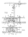
- la figure 1 est une vue schématique en perspective, éclatée, montrant les différents éléments d'un dispositif conforme à l'invention ;
- la figure 2 est une vue en coupe horizontale, montrant la manière dont est réalisé le montage de deux panneaux consécutifs grâce à un dispositif conforme à l'invention, le joint d'étanchéité n'étant pas encore mis en action ;
- la figure 3 est une vue partielle de la figure 2, montrant plus en détail l'action du joint d'étanchéité sur les deux panneaux ;
- la figure 4 est une vue éclatée d'une variante d'un dispositif conforme à l'invention.
- Figure 1 is a schematic perspective view, exploded, showing the various elements of a device according to the invention;
- Figure 2 is a horizontal sectional view showing the manner in which the mounting of two consecutive panels is carried out using a device according to the invention, the seal not yet being put into action;
- Figure 3 is a partial view of Figure 2, showing in more detail the action of the seal on the two panels;
- Figure 4 is an exploded view of a variant of a device according to the invention.
Si l'on se reporte aux schémas annexés, l'invention concerne un perfectionnement à la réalisation d'un revêtement de façades au moyen de panneaux élémentaires fixés contre ladite façade, espacés de cette dernière de manière à emprisonner de préférence une couche d'isolants thermiques.If reference is made to the appended diagrams, the invention relates to an improvement in the production of a coating of facades by means of elementary panels fixed against said facade, spaced from the latter so as to preferably trap a layer of insulation. thermi ques.
Les panneaux élémentaires susceptibles d'être utilisés pour la mise en oeuvre de l'invention pourront être à base de tous matériaux couramment utilisés pour une telle application, par exemple réalisés à partir d'un matériau lamifié. Ces plaques pourront également avoir des dimensions variables. Par exemple, on pourra utiliser des plaques de 1 m x 1,50 m ayant une épaisseur de 6 mm. Bien entendu, cela n'est pas limitatif et d'autres dimensions de plaques pourraient être utilisées sans sortir du cadre de l'invention.The elementary panels capable of being used for the implementation of the invention may be based on any material commonly used for such an application, for example made from a laminated material. These plates may also have variable dimensions. For example, plates of 1 m x 1.50 m having a thickness of 6 mm could be used. Of course, this is not limiting and other dimensions of plates could be used without departing from the scope of the invention.
Ces plaques sont prédécoupées en usine et éventuellement revêtues d'une couche de finition extérieure, par exemple d'un crépi.These plates are pre-cut in the factory and possibly coated with an exterior finishing layer, for example a plaster.
Les figures annexées illustrent deux modes de réalisation d'un dispositif permettant, conformément à l'invention, la fixation de plaques élémentaires (1, 2) contre un mur (3).The appended figures illustrate two embodiments of a device allowing, in accordance with the invention, the fixing of elementary plates (1, 2) against a wall (3).
Selon un premier mode de réalisation illustré par les figures 1, 2 et 3, chacune des plaques (1, 2) comporte sur sa face arrière, disposées horizontalement, des glissières (4) au moins au nombre de deux sur la hauteur, et constituées par des profils en forme de U fixés aux plaques (1, 2) au moyen de boulons (5). Le montage de ces glissières (4) est réalisé en usine.According to a first embodiment illustrated by Figures 1, 2 and 3, each of the plates (1, 2) has on its rear face, arranged horizontally, slides (4) at least two in number on the height, and constituted by U-shaped profiles fixed to the plates (1, 2) by means of bolts (5). The mounting of these slides (4) is carried out in the factory.
La fixation des panneaux élémentaires ainsi formés contre la façade (3) est réalisée conformément à l'invention au moyen d'un ensemble permettant, d'une part de maintenir les plaques (1, 2) espacées de la façade (3) pour interposer une couche d'isolant, formée par exemple de panneaux rigides de laine minérale fixés au gros oeuvre de manière conventionnelle et, d'autre part, assurer la liaison entre les plaques consécutives ainsi que l'étanchéité entre ces plaques.The fixing of the elementary panels thus formed against the facade (3) is carried out in accordance with the invention by means of an assembly making it possible, on the one hand to maintain the plates (1, 2) spaced from the facade (3) to interpose an insulating layer, formed for example of rigid panels of mineral wool fixed to structural work in a conventional manner and, on the other hand, ensuring the connection between the consecutive plates as well as the sealing between these plates.
Cet ensemble comporte un système à équerres, formé de deux équerres élémentaires (7, 8), l'une (7) étant fixée contre le mur (3) au moyen de vis (ou équivalent) (9), des lumières (10) étant avantageusement prévues pour permettre un réglage transversal, l'autre (8) étant fixée sur la branche (11) de l'équerre (7), de préférence de manière réglable par rapport à ces branches, par exemple en prévoyant une lumière (12) sur cette branche (11). Les équerres (7, 8) permettent donc de réaliser un réglage horizontal parallèlement et perpendiculairement au mur.This set comprises a system of brackets, formed of two elementary brackets (7, 8), one (7) being fixed against the wall (3) by means of screws (or equivalent) (9), lights (10) being advantageously provided to allow a transverse adjustment, the other (8) being fixed on the branch (11) of the bracket (7), preferably in an adjustable manner with respect to these branches, for example by providing a light (12 ) on this branch (11). The brackets (7, 8) therefore allow horizontal adjustment to be made parallel and perpendicular to the wall.
Sur la partie frontale (13) de l'équerre (8), est fixée une griffe (6), en forme de U, débordant de part et d'autre de cette équerre. Cette griffe (6) supporte un couvre-joints intérieur (14), qui est à base d'un matériau similaire à celui des plaques (1, 2), présentant sur sa face avant des bandes assurant l'étanchéité (15), constituées par exemple de bandes adhésives de mousse. Ce joint (14) est fixé sur un profil métallique (16) au moyen de vis (17) afin d'assurer la rigidité de l'ensemble. Ces éléments joints (14)-profil (16) sont montés sur la griffe (8) et la partie (13) de l'équerre au moyen d'une vis spéciale (18) et un écrou (19), cette vis à collerette, elle-même taraudée dans son centre, reçoit une autre vis (21), commandée par l'extérieur du joint. Cette vis à collerette est à pas à gauche, permet, lorsque l'ensemble est mis en place, de venir faire plaquer le bloc joint contre l'arrière des panneaux (1, 2) (voir figure 3). La mise en place des panneaux élémentaires grâce au dispositif conforme à l'invention est réalisée de la manière suivante.On the front part (13) of the bracket (8), is fixed a claw (6), in the shape of a U, projecting on either side of this bracket. This claw (6) supports an interior joint cover (14), which is based on a material similar to that of the plates (1, 2), having on its front face sealing strips (15), constituted for example foam adhesive strips. This seal (14) is fixed to a metal profile (16) by means of screws (17) in order to ensure the rigidity of the assembly. These joint elements (14) -profile (16) are mounted on the claw (8) and the part (13) of the bracket by means of a special screw (18) and a nut (19), this flanged screw , itself tapped in its center, receives another screw (21), controlled from the outside of the seal. This flanged screw is left-hand, allows, when the assembly is in place, to press the joint block against the rear of the panels (1, 2) (see Figure 3). The establishment of the elementary panels using the device according to the invention is carried out as follows.
Dans un premier temps, les équerres (7, 8) sont montées contre le mur et réglées, la griffe (6) ayant été enlevée.First, the brackets (7, 8) are mounted against the wall and adjusted, the claw (6) having been removed.
La griffe (6) est alors mise en place avec le joint (14) qui est maintenu totalement desserré (voir figure 2). On introduit alors l'extrémité de la griffe à l'intérieur des glissières (4) prévues à l'arrière des panneaux et, après avoir réglé les niveaux, on bloque les écrous de serrage (19, 20) des griffes. La plaque suivante est montée de l'autre côté et ainsi de suite. La fixation définitive des plaques (1, 2) et la réalisation d'étanchéité entre ces plaques est alors réalisée en serrant le bloc joint (14) au moyen du système à vis (21) qui, comme dit précédemment, a un pas à gauche.The claw (6) is then put in place with the seal (14) which is kept completely loose (see FIG. 2). The end of the claw is then introduced inside the slides (4) provided at the rear of the panels and, after having adjusted the levels, the clamping nuts (19, 20) of the claws are blocked. The next plate is mounted on the other side and so on. The final fixing of the plates (1, 2) and the sealing between these plates is then carried out by tightening the joint block (14) by means of the screw system (21) which, as said previously, has a step to the left .
Le second mode de réalisation conforme à l'invention illustré par la figure 4, figure sur laquelle les mêmes références ont été utilisées pour désigner les éléments similaires ou équivalents de ceux de l'exemple donné précédemment se différencie de cet exemple essentiellement par le fait que les plaques élémentaires (1, 2), destinées à former le revêtement, comportent sur leur face arrière non seulement des glissières horizontales (4) espacées les unes des autres (une seule de ces glissières étant représentée), mais également des glissières additionnelles verticales (4b) disposées entre les glissières horizontales (4) légèrement en retrait par rapport aux bords latéraux (22, 23) des plaques élémentaires (1, 2). Dans ce mode de réalisation, le système à griffes susceptible d'être introduit à l'intérieur des glissières de deux panneaux consécutifs est constitué par une plaque (6), débordante, susceptible d'être introduite dans les lumières (24) des glissières verticales (4b).The second embodiment in accordance with the invention illustrated by FIG. 4, a figure in which the same references have been used to designate elements similar or equivalent to those of the example given above differs from this example essentially by the fact that the elementary plates (1, 2), intended to form the covering, comprise on their rear face not only horizontal slides (4) spaced from one another (only one of these slides being shown), but also additional vertical slides ( 4b) arranged between the horizontal slides (4) slightly set back relative to the lateral edges (22, 23) of the elementary plates (1, 2). In this embodiment, the claw system capable of being introduced inside the slides of two consecutive panels consists of a plate (6), projecting, capable of being introduced into the slots (24) of the vertical slides (4b).
Les dispositifs conformes à l'invention décrits précédemment permettent d'obtenir une immobilisation parfaite des plaques de revêtement ainsi qu'une très bonne étanchéité, les joints ne pouvant pas être enlevés.The devices according to the invention described above make it possible to obtain perfect immobilization of the covering plates as well as a very good seal, the seals cannot be removed.
Par rapport aux solutions antérieures, les dispositifs conformes à l'invention présentent de nombreux avantages par le fait que l'ensemble des éléments (plaques et fixations) peuvent être préparés en usine et que seules les opérations simples de réglage et de mise en place sont réalisées sur le chantier.Compared to previous solutions, the devices according to the invention have numerous advantages in that all of the elements (plates and fixings) can be prepared in the factory and that only the simple adjustment and positioning operations are carried out on site.
Par ailleurs, il convient de noter que dans la variante faisant l'objet de la figure 4, un joint horizontal additionnel (25) peut être introduit entre les panneaux proprement dits (1, 2) et les glissières verticales (4b).Furthermore, it should be noted that in the variant which is the subject of FIG. 4, an additional horizontal seal (25) can be introduced between the panels proper (1, 2) and the vertical slides (4b).
Claims (8)
Priority Applications (1)
| Application Number | Priority Date | Filing Date | Title |
|---|---|---|---|
| AT84420116T ATE25731T1 (en) | 1983-07-28 | 1984-07-05 | DEVICE FOR FIXING AND SEALING PANELS MOUNTED ON FAÇADES OF DIFFERENT CONSTRUCTIONS. |
Applications Claiming Priority (2)
| Application Number | Priority Date | Filing Date | Title |
|---|---|---|---|
| FR8312674A FR2549876B1 (en) | 1983-07-28 | 1983-07-28 | DEVICE FOR ENSURING FIXING AND SEALING OF PANELS MOUNTED ON VARIOUS CONSTRUCTION FACADES |
| FR8312674 | 1983-07-28 |
Publications (2)
| Publication Number | Publication Date |
|---|---|
| EP0133140A1 EP0133140A1 (en) | 1985-02-13 |
| EP0133140B1 true EP0133140B1 (en) | 1987-03-04 |
Family
ID=9291305
Family Applications (1)
| Application Number | Title | Priority Date | Filing Date |
|---|---|---|---|
| EP84420116A Expired EP0133140B1 (en) | 1983-07-28 | 1984-07-05 | Apparatus to fix and seal plates assembled on different building façades |
Country Status (4)
| Country | Link |
|---|---|
| EP (1) | EP0133140B1 (en) |
| AT (1) | ATE25731T1 (en) |
| DE (1) | DE3462530D1 (en) |
| FR (1) | FR2549876B1 (en) |
Families Citing this family (4)
| Publication number | Priority date | Publication date | Assignee | Title |
|---|---|---|---|---|
| DE59807361D1 (en) * | 1997-08-29 | 2003-04-10 | Villeroy & Boch Wellness B V | Adjustment element for a shower device or the like |
| DE10003311A1 (en) * | 2000-01-27 | 2001-08-02 | Fischer Artur Werke Gmbh | Adjustment element for fastening a facade panel |
| GB2504661A (en) * | 2012-06-22 | 2014-02-12 | Aqualux Products Ltd | Improvements in or relating to adjustable mounting mechanisms |
| CN104278754A (en) * | 2013-07-04 | 2015-01-14 | 常州市月仙冷藏设备有限公司 | Connecting structure for common wall board and position difference roofs of refrigeration house |
Family Cites Families (1)
| Publication number | Priority date | Publication date | Assignee | Title |
|---|---|---|---|---|
| FR2308746A1 (en) * | 1975-04-24 | 1976-11-19 | Safama | DEVICE INTENDED FOR HANGING PANELS ON A WALL WITH A VIEW TO CONSTITUTING A COATING ON THIS WALL |
-
1983
- 1983-07-28 FR FR8312674A patent/FR2549876B1/en not_active Expired
-
1984
- 1984-07-05 AT AT84420116T patent/ATE25731T1/en not_active IP Right Cessation
- 1984-07-05 EP EP84420116A patent/EP0133140B1/en not_active Expired
- 1984-07-05 DE DE8484420116T patent/DE3462530D1/en not_active Expired
Also Published As
| Publication number | Publication date |
|---|---|
| DE3462530D1 (en) | 1987-04-09 |
| EP0133140A1 (en) | 1985-02-13 |
| ATE25731T1 (en) | 1987-03-15 |
| FR2549876A1 (en) | 1985-02-01 |
| FR2549876B1 (en) | 1985-11-08 |
Similar Documents
| Publication | Publication Date | Title |
|---|---|---|
| WO2011023898A1 (en) | Device for attaching at least one panel onto a supporting structure | |
| EP0133140B1 (en) | Apparatus to fix and seal plates assembled on different building façades | |
| FR2800768A1 (en) | Building facade cantilever bracket assembly and fixing system esp for curtain walling uses solid plates sliding in metal framework members | |
| EP2687647B1 (en) | Device for covering an outer surface or a building such as a veranda or pergola, and assembly method thereof | |
| EP0764749B1 (en) | Support assembly of a cantilevered element vis à vis the vertical façade of a curtain wall of a building or similar construction | |
| FR2553454A1 (en) | Device for covering walls, floors, furniture and similar applications | |
| FR2969189A1 (en) | ELEMENT SUPPORT DEVICE IN ROOF COVER AND FACADE COVER | |
| EP0426187A1 (en) | Façade system for the closing off of buildings from floor slab to floor slab | |
| FR2526837A1 (en) | Facade panel for buildings etc. - comprises parallelepiped moulding supported by brackets extending from wall | |
| EP0191709A1 (en) | Method of insulation by cladding | |
| FR2657375A1 (en) | MODULAR ROOM FOR CONSTRUCTING THE PREMISES. | |
| EP2005011B1 (en) | Corner assembly comprising a male element preformed to a predetermined angle and bordered by returns | |
| FR2624159A1 (en) | Curtain-wall-type elevation assembly | |
| EP0893548B1 (en) | Holding device for panels for a vertical curtain wall for buildings | |
| FR2484011A1 (en) | Joint for corners of insulated door opening - is clipped to masonry via bar and has leg step defining flush edge of rendering | |
| FR2753733A1 (en) | Device for mounting of hollow support post for internal partition used e.g. in offices | |
| FR2480844A1 (en) | Purlin mounted joint for glazed panels - uses inter-housed winged Y-sections to clamp panel edges on seals and over sheet metal drain troughs | |
| FR2628785A1 (en) | HARDWARE IN THIN SHEET FOR THE SOLIDARIZATION OF A COVERING ELEMENT FOR ROOF OPENINGS | |
| FR2729174A1 (en) | Mounting of building facing | |
| FR2508515A1 (en) | Removable partition with metal frame - has three branch profile joint to allow several deployment positions | |
| EP1229179A1 (en) | Ruptured thermal bridge for metal sections | |
| EP1503028A1 (en) | Fixing arrangement for security clamps or pieces for glazing panels in curtain walls | |
| FR2689541A1 (en) | Assembly for making movable double-skinned partitions - comprises main extrusion with side projections to engage with joint covers | |
| FR2734297A1 (en) | Structure parts for building framework | |
| FR2746125A1 (en) | Glazing support for building partition |
Legal Events
| Date | Code | Title | Description |
|---|---|---|---|
| PUAI | Public reference made under article 153(3) epc to a published international application that has entered the european phase |
Free format text: ORIGINAL CODE: 0009012 |
|
| AK | Designated contracting states |
Designated state(s): AT CH DE IT LI |
|
| 17P | Request for examination filed |
Effective date: 19850523 |
|
| ITF | It: translation for a ep patent filed |
Owner name: MANZONI & MANZONI |
|
| GRAA | (expected) grant |
Free format text: ORIGINAL CODE: 0009210 |
|
| AK | Designated contracting states |
Kind code of ref document: B1 Designated state(s): AT CH DE IT LI |
|
| REF | Corresponds to: |
Ref document number: 25731 Country of ref document: AT Date of ref document: 19870315 Kind code of ref document: T |
|
| REF | Corresponds to: |
Ref document number: 3462530 Country of ref document: DE Date of ref document: 19870409 |
|
| PLBE | No opposition filed within time limit |
Free format text: ORIGINAL CODE: 0009261 |
|
| STAA | Information on the status of an ep patent application or granted ep patent |
Free format text: STATUS: NO OPPOSITION FILED WITHIN TIME LIMIT |
|
| 26N | No opposition filed | ||
| PG25 | Lapsed in a contracting state [announced via postgrant information from national office to epo] |
Ref country code: AT Effective date: 19880705 |
|
| PG25 | Lapsed in a contracting state [announced via postgrant information from national office to epo] |
Ref country code: LI Effective date: 19880731 Ref country code: CH Effective date: 19880731 |
|
| REG | Reference to a national code |
Ref country code: CH Ref legal event code: PL Ref country code: CH Ref legal event code: AUV Free format text: LE BREVET CI-DESSUS EST TOMBE EN DECHEANCE FAUTE DE PAIEMENT, DE LA 5E ANNUITE. |
|
| PG25 | Lapsed in a contracting state [announced via postgrant information from national office to epo] |
Ref country code: DE Effective date: 19890401 |