EP0133140B1 - Vorrichtung zur Befestigung und Abdichtung von Platten die auf Fassaden verschiedener Konstruktion montiert werden - Google Patents
Vorrichtung zur Befestigung und Abdichtung von Platten die auf Fassaden verschiedener Konstruktion montiert werden Download PDFInfo
- Publication number
- EP0133140B1 EP0133140B1 EP84420116A EP84420116A EP0133140B1 EP 0133140 B1 EP0133140 B1 EP 0133140B1 EP 84420116 A EP84420116 A EP 84420116A EP 84420116 A EP84420116 A EP 84420116A EP 0133140 B1 EP0133140 B1 EP 0133140B1
- Authority
- EP
- European Patent Office
- Prior art keywords
- panels
- fixed
- brackets
- elementary
- wall
- Prior art date
- Legal status (The legal status is an assumption and is not a legal conclusion. Google has not performed a legal analysis and makes no representation as to the accuracy of the status listed.)
- Expired
Links
Images


Classifications
-
- E—FIXED CONSTRUCTIONS
- E04—BUILDING
- E04F—FINISHING WORK ON BUILDINGS, e.g. STAIRS, FLOORS
- E04F13/00—Coverings or linings, e.g. for walls or ceilings
- E04F13/07—Coverings or linings, e.g. for walls or ceilings composed of covering or lining elements; Sub-structures therefor; Fastening means therefor
- E04F13/08—Coverings or linings, e.g. for walls or ceilings composed of covering or lining elements; Sub-structures therefor; Fastening means therefor composed of a plurality of similar covering or lining elements
- E04F13/0801—Separate fastening elements
- E04F13/0803—Separate fastening elements with load-supporting elongated furring elements between wall and covering elements
- E04F13/081—Separate fastening elements with load-supporting elongated furring elements between wall and covering elements with additional fastening elements between furring elements and covering elements
- E04F13/0814—Separate fastening elements with load-supporting elongated furring elements between wall and covering elements with additional fastening elements between furring elements and covering elements fixed by means of clamping action
Definitions
- the present invention relates to an improved device for ensuring the fixing and sealing between the panels (cladding) commonly used to cover the facades of various constructions in order, on the one hand, to ensure the finish and, on the other hand, to provide external thermal insulation.
- Such panels commonly designated by the expression “cladding can be based on various materials such as slate, fiber cement stone, laminate ...
- the horizontal slides fixed to the rear of the elementary plates intended to form the covering are in the form of brackets, spaced from one another and between which are arranged, vertically, slightly recessed relative to the edge of the panel, additional vertical brackets.
- These horizontal and vertical brackets have regularly spaced along their length, lights.
- the connection is also obtained by means of a claw system capable of being introduced inside the lights of the vertical brackets of two consecutive panels. This variant makes it possible to obtain a perfect blocking of the panels as well as a possibility of adjustment in the vertical direction and a strengthening of the plate which prevents it from deforming.
- the invention relates to an improvement in the production of a coating of facades by means of elementary panels fixed against said facade, spaced from the latter so as to preferably trap a layer of insulation. thermi ques.
- the elementary panels capable of being used for the implementation of the invention may be based on any material commonly used for such an application, for example made from a laminated material. These plates may also have variable dimensions. For example, plates of 1 m x 1.50 m having a thickness of 6 mm could be used. Of course, this is not limiting and other dimensions of plates could be used without departing from the scope of the invention.
- These plates are pre-cut in the factory and possibly coated with an exterior finishing layer, for example a plaster.
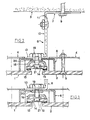
- the appended figures illustrate two embodiments of a device allowing, in accordance with the invention, the fixing of elementary plates (1, 2) against a wall (3).
- each of the plates (1, 2) has on its rear face, arranged horizontally, slides (4) at least two in number on the height, and constituted by U-shaped profiles fixed to the plates (1, 2) by means of bolts (5).
- the mounting of these slides (4) is carried out in the factory.
- the fixing of the elementary panels thus formed against the facade (3) is carried out in accordance with the invention by means of an assembly making it possible, on the one hand to maintain the plates (1, 2) spaced from the facade (3) to interpose an insulating layer, formed for example of rigid panels of mineral wool fixed to structural work in a conventional manner and, on the other hand, ensuring the connection between the consecutive plates as well as the sealing between these plates.
- This set comprises a system of brackets, formed of two elementary brackets (7, 8), one (7) being fixed against the wall (3) by means of screws (or equivalent) (9), lights (10) being advantageously provided to allow a transverse adjustment, the other (8) being fixed on the branch (11) of the bracket (7), preferably in an adjustable manner with respect to these branches, for example by providing a light (12 ) on this branch (11).
- the brackets (7, 8) therefore allow horizontal adjustment to be made parallel and perpendicular to the wall.
- a claw (6) On the front part (13) of the bracket (8), is fixed a claw (6), in the shape of a U, projecting on either side of this bracket.
- This claw (6) supports an interior joint cover (14), which is based on a material similar to that of the plates (1, 2), having on its front face sealing strips (15), constituted for example foam adhesive strips.
- This seal (14) is fixed to a metal profile (16) by means of screws (17) in order to ensure the rigidity of the assembly.
- These joint elements (14) -profile (16) are mounted on the claw (8) and the part (13) of the bracket by means of a special screw (18) and a nut (19), this flanged screw , itself tapped in its center, receives another screw (21), controlled from the outside of the seal.
- This flanged screw is left-hand, allows, when the assembly is in place, to press the joint block against the rear of the panels (1, 2) (see Figure 3).
- brackets (7, 8) are mounted against the wall and adjusted, the claw (6) having been removed.
- the claw (6) is then put in place with the seal (14) which is kept completely loose (see FIG. 2).
- the end of the claw is then introduced inside the slides (4) provided at the rear of the panels and, after having adjusted the levels, the clamping nuts (19, 20) of the claws are blocked.
- the next plate is mounted on the other side and so on.
- the final fixing of the plates (1, 2) and the sealing between these plates is then carried out by tightening the joint block (14) by means of the screw system (21) which, as said previously, has a step to the left .
- FIG. 4 a figure in which the same references have been used to designate elements similar or equivalent to those of the example given above differs from this example essentially by the fact that the elementary plates (1, 2), intended to form the covering, comprise on their rear face not only horizontal slides (4) spaced from one another (only one of these slides being shown), but also additional vertical slides ( 4b) arranged between the horizontal slides (4) slightly set back relative to the lateral edges (22, 23) of the elementary plates (1, 2).
- the claw system capable of being introduced inside the slides of two consecutive panels consists of a plate (6), projecting, capable of being introduced into the slots (24) of the vertical slides (4b).
- the devices according to the invention have numerous advantages in that all of the elements (plates and fixings) can be prepared in the factory and that only the simple adjustment and positioning operations are carried out on site.
Claims (8)
Priority Applications (1)
| Application Number | Priority Date | Filing Date | Title |
|---|---|---|---|
| AT84420116T ATE25731T1 (de) | 1983-07-28 | 1984-07-05 | Vorrichtung zur befestigung und abdichtung von platten die auf fassaden verschiedener konstruktion montiert werden. |
Applications Claiming Priority (2)
| Application Number | Priority Date | Filing Date | Title |
|---|---|---|---|
| FR8312674A FR2549876B1 (fr) | 1983-07-28 | 1983-07-28 | Dispositif permettant d'assurer la fixation et l'etancheite de panneaux rapportes sur les facades de constructions diverses |
| FR8312674 | 1983-07-28 |
Publications (2)
| Publication Number | Publication Date |
|---|---|
| EP0133140A1 EP0133140A1 (de) | 1985-02-13 |
| EP0133140B1 true EP0133140B1 (de) | 1987-03-04 |
Family
ID=9291305
Family Applications (1)
| Application Number | Title | Priority Date | Filing Date |
|---|---|---|---|
| EP84420116A Expired EP0133140B1 (de) | 1983-07-28 | 1984-07-05 | Vorrichtung zur Befestigung und Abdichtung von Platten die auf Fassaden verschiedener Konstruktion montiert werden |
Country Status (4)
| Country | Link |
|---|---|
| EP (1) | EP0133140B1 (de) |
| AT (1) | ATE25731T1 (de) |
| DE (1) | DE3462530D1 (de) |
| FR (1) | FR2549876B1 (de) |
Families Citing this family (4)
| Publication number | Priority date | Publication date | Assignee | Title |
|---|---|---|---|---|
| EP0898919B1 (de) * | 1997-08-29 | 2003-03-05 | Villeroy & Boch Wellness B.V. | Verstellelement für eine Duschvorrichtung oder dgl. |
| DE10003311A1 (de) * | 2000-01-27 | 2001-08-02 | Fischer Artur Werke Gmbh | Justierelement zur Befestigung einer Fassadenplatte |
| GB2504661A (en) * | 2012-06-22 | 2014-02-12 | Aqualux Products Ltd | Improvements in or relating to adjustable mounting mechanisms |
| CN104278754A (zh) * | 2013-07-04 | 2015-01-14 | 常州市月仙冷藏设备有限公司 | 一种冷库的共用墙板与有位差顶板连接结构 |
Family Cites Families (1)
| Publication number | Priority date | Publication date | Assignee | Title |
|---|---|---|---|---|
| FR2308746A1 (fr) * | 1975-04-24 | 1976-11-19 | Safama | Dispositif destine a l'accrochage de panneaux sur une paroi en vue de constituer un revetement a cette paroi |
-
1983
- 1983-07-28 FR FR8312674A patent/FR2549876B1/fr not_active Expired
-
1984
- 1984-07-05 AT AT84420116T patent/ATE25731T1/de not_active IP Right Cessation
- 1984-07-05 EP EP84420116A patent/EP0133140B1/de not_active Expired
- 1984-07-05 DE DE8484420116T patent/DE3462530D1/de not_active Expired
Also Published As
| Publication number | Publication date |
|---|---|
| FR2549876B1 (fr) | 1985-11-08 |
| FR2549876A1 (fr) | 1985-02-01 |
| DE3462530D1 (en) | 1987-04-09 |
| ATE25731T1 (de) | 1987-03-15 |
| EP0133140A1 (de) | 1985-02-13 |
Similar Documents
| Publication | Publication Date | Title |
|---|---|---|
| WO2011023898A1 (fr) | Dispositif de fixation d'au moins un panneau sur une structure porteuse | |
| EP0133140B1 (de) | Vorrichtung zur Befestigung und Abdichtung von Platten die auf Fassaden verschiedener Konstruktion montiert werden | |
| EP2687647B1 (de) | Abdeckvorrichtung einer äußeren Oberfläche oder eines Gebäudes vom Typ Veranda oder Pergola, und Verfahren zum Zusammenbau | |
| EP0764749B1 (de) | Haltevorrichtung für ein, gegenüber der vertikalen Fassade einer Vorhängewand eines Gebäudes oder ähnlichen Konstruktion, freitragendes Element | |
| FR2553454A1 (fr) | Dispositif de revetement pour murs, sols, meubles et applications analogues | |
| FR2969189A1 (fr) | Dispositif support d'element en couverture de toiture et en recouvrement de facade | |
| EP0426187A1 (de) | Fassadensystem zur Abschliessung von Gebäuden von Decke zu Decke | |
| EP0191709A1 (de) | Verfahren zum Isolieren durch Verkleidung | |
| FR2657375A1 (fr) | Cloison modulaire destinee a construire les locaux. | |
| EP2005011B1 (de) | Ein in einen bestimmten winkel vorgeformtes und durch rücksprünge begrenztes steckelement umfassende eckanordnung | |
| FR2624159A1 (fr) | Ensemble de facade du type mur-rideau | |
| EP0893548B1 (de) | Befestigungsvorrichtung für Paneele einer vertikalen Vorhängewand für Gebäude | |
| FR2484011A1 (fr) | Dispositif de maintien d'une isolation autour de portes et fenetres | |
| FR2753733A1 (fr) | Dispositif de montage et d'immobilisation d'un poteau de support creux pour cloison interieure d'un local | |
| EP1715131B1 (de) | Vorrichtung zur Verwirklichung oder Erneuerung von Innentüren | |
| FR2628785A1 (fr) | Huisserie en tole mince, pour la solidarisation d'un element de recouvrement d'ouvertures de toitures | |
| FR2729174A1 (fr) | Dispositif pour le montage et la fixation d'un revetement de facade. | |
| FR2508515A1 (fr) | Cloison industrialisee amovible de structure metallique et son procede de mise en oeuvre | |
| EP1229179A1 (de) | Unterbrochene Wärmebrücke für metallische Profile | |
| EP1503028A1 (de) | Befestigungsanordnung für Sicherheitsklammern oder -teile für Verglasungstafeln in Vorhangfassaden | |
| FR2689541A1 (fr) | Ensemble de construction pour la réalisation de cloisons amovibles. | |
| FR2734297A1 (fr) | Element de structure pour la realisation d'ossatures de batiments | |
| FR2746125A1 (fr) | Ensemble pour la fixation et l'assemblage de panneaux de parement et cloison amovible comprenant un tel ensemble | |
| FR2728053A1 (fr) | Dispositif d'assemblage pour la realisation d'armatures metalliques | |
| FR2770245A1 (fr) | Equerre de fixation et d'assemblage integree a un compensateur de dilatation pour la realisation de vetage dans le batiment |
Legal Events
| Date | Code | Title | Description |
|---|---|---|---|
| PUAI | Public reference made under article 153(3) epc to a published international application that has entered the european phase |
Free format text: ORIGINAL CODE: 0009012 |
|
| AK | Designated contracting states |
Designated state(s): AT CH DE IT LI |
|
| 17P | Request for examination filed |
Effective date: 19850523 |
|
| ITF | It: translation for a ep patent filed |
Owner name: MANZONI & MANZONI |
|
| GRAA | (expected) grant |
Free format text: ORIGINAL CODE: 0009210 |
|
| AK | Designated contracting states |
Kind code of ref document: B1 Designated state(s): AT CH DE IT LI |
|
| REF | Corresponds to: |
Ref document number: 25731 Country of ref document: AT Date of ref document: 19870315 Kind code of ref document: T |
|
| REF | Corresponds to: |
Ref document number: 3462530 Country of ref document: DE Date of ref document: 19870409 |
|
| PLBE | No opposition filed within time limit |
Free format text: ORIGINAL CODE: 0009261 |
|
| STAA | Information on the status of an ep patent application or granted ep patent |
Free format text: STATUS: NO OPPOSITION FILED WITHIN TIME LIMIT |
|
| 26N | No opposition filed | ||
| PG25 | Lapsed in a contracting state [announced via postgrant information from national office to epo] |
Ref country code: AT Effective date: 19880705 |
|
| PG25 | Lapsed in a contracting state [announced via postgrant information from national office to epo] |
Ref country code: LI Effective date: 19880731 Ref country code: CH Effective date: 19880731 |
|
| REG | Reference to a national code |
Ref country code: CH Ref legal event code: PL Ref country code: CH Ref legal event code: AUV Free format text: LE BREVET CI-DESSUS EST TOMBE EN DECHEANCE FAUTE DE PAIEMENT, DE LA 5E ANNUITE. |
|
| PG25 | Lapsed in a contracting state [announced via postgrant information from national office to epo] |
Ref country code: DE Effective date: 19890401 |