EP0132487B1 - Procédé de régulation d'au moins deux turbo-compresseurs branchés en parallèle - Google Patents
Procédé de régulation d'au moins deux turbo-compresseurs branchés en parallèle Download PDFInfo
- Publication number
- EP0132487B1 EP0132487B1 EP84100822A EP84100822A EP0132487B1 EP 0132487 B1 EP0132487 B1 EP 0132487B1 EP 84100822 A EP84100822 A EP 84100822A EP 84100822 A EP84100822 A EP 84100822A EP 0132487 B1 EP0132487 B1 EP 0132487B1
- Authority
- EP
- European Patent Office
- Prior art keywords
- control
- pressure
- compressors
- controller
- blow
- Prior art date
- Legal status (The legal status is an assumption and is not a legal conclusion. Google has not performed a legal analysis and makes no representation as to the accuracy of the status listed.)
- Expired
Links
Images


Classifications
-
- F—MECHANICAL ENGINEERING; LIGHTING; HEATING; WEAPONS; BLASTING
- F04—POSITIVE - DISPLACEMENT MACHINES FOR LIQUIDS; PUMPS FOR LIQUIDS OR ELASTIC FLUIDS
- F04D—NON-POSITIVE-DISPLACEMENT PUMPS
- F04D27/00—Control, e.g. regulation, of pumps, pumping installations or pumping systems specially adapted for elastic fluids
- F04D27/02—Surge control
- F04D27/0253—Surge control by throttling
-
- F—MECHANICAL ENGINEERING; LIGHTING; HEATING; WEAPONS; BLASTING
- F04—POSITIVE - DISPLACEMENT MACHINES FOR LIQUIDS; PUMPS FOR LIQUIDS OR ELASTIC FLUIDS
- F04D—NON-POSITIVE-DISPLACEMENT PUMPS
- F04D27/00—Control, e.g. regulation, of pumps, pumping installations or pumping systems specially adapted for elastic fluids
- F04D27/02—Surge control
- F04D27/0269—Surge control by changing flow path between different stages or between a plurality of compressors; load distribution between compressors
Definitions
- the invention relates to a method for operating at least two turbocompressors connected in parallel, each of which is provided with a surge limit control to prevent pumping, i. H. that before reaching the surge limit when reaching a blow-off line running parallel to this, opening blow-off or blow-off valves ensures that pumping is avoided, and the turbo-compressors are also controlled jointly by load distribution regulators and individually by a pressure regulator.
- Each flow controller has the same setpoint (output of the pressure controller) and consequently leads each machine to the operating point at which it is operated with the same throughput as the parallel machine (s).
- the parallel machine s
- a typical suitable surge limit control is e.g. B. described in D-A 2 623 899. On the basis of a correspondingly increasing control characteristic curve, it ensures that a blow-off takes place in time so that pumping is reliably prevented.
- the surge limit control is initially set in a stable manner.
- the flow control must then react much more slowly to avoid repercussions.
- the pressure control as a superimposed master control must in turn react much more slowly.
- the load distribution control has the task of preventing operating states in which one machine is blowing off while other machines or another machine are driving far in the map. A regulation for setting the same flow cannot fully accomplish this task. So z. B. asymmetries in the course of the characteristic curves or the blow-off lines, as described above, are compensated for just as little as the influence of different suction pressures or an asymmetrical flow course in the pipelines.
- turbocompressors should be able to be operated under the most favorable conditions, taking into account their individual values, and they should be able to be adapted to possible pressure and flow fluctuations as quickly as possible, the entire control system being supposed to be safe, prone to failure and economical. In particular, the entire regulation should be able to be implemented using commercially available components.
- the load distribution regulators regulate the setting of the compressors with one another in such a way that the operating point is at the same distance from the blow-off line, with only one of the compressors being controlled by its pressure regulator and the rest via the pressure regulator Load distribution control are tracked, in which the pressure regulator is set to automatic by its pressure regulator-controlled compressor, while the pressure regulators of the other compressors are set to manual operation and a control difference between the pressure control and the load distribution control is formed, these control differences are added and there is a comparison, until the sum of the differences is zero. This also ensures that there is also an optimal distance of the working points from the blow-off line in the control phase.
- each compressor has its own pressure control, which acts directly on the throttle valve.
- the pressure control can thus be made in the time behavior as quickly as in the known system of the flow controller.
- the pressure regulators are interlocked in such a way that only a maximum of one pressure regulator can be switched to automatic.
- the other or the other is or are switched to hand, i. H. passive as long as there is no manual intervention.
- FC parallel load distribution controller
- This variable is identical to the control difference x d of the surge limit control (FSC) and is available there as a signal, so it does not need to be determined or measured separately.
- the determination of such a signal goes z. B. from German patent application P 26 23 899.3, in which a corresponding pressure-flow diagram is shown, which contains a surge line and blow-off line and operating curves of turbo compressors. Otherwise, the terms mentioned are generally known to the person skilled in the art.
- the control difference of one machine (xd (A)) is different than that of the other machine (xd (B)).
- the difference between these two quantities is applied as a correction quantity (actual value) to the two load distribution controllers, with a different sign.
- the setpoint of these controllers is usually set to zero, but it can also assume other values if an asymmetry is desired.
- the output of the load distribution controller has an additive effect on the output of the pressure controller. If there is a different load on the machines, one load distribution controller continues to open the throttle valve, while the other closes the flap of the parallel machine (s) to the same extent. Assuming linear characteristics of the throttle valves, the overall throughput of the machines and thus the final pressure are not influenced by this control process. In a real system, the pressure regulator only needs to readjust the asymmetries of the throttle valves.
- the pressure controller first tracks the machine that is set to automatic. The resulting asymmetry in the machine load is detected by the load distribution controller, which then adjusts all machines until the symmetry is reached again.
- FIG. 3 shows such a tracking circuit. Controllers are used whose output size can be limited to an externally adjustable value. Overdriving is prevented if the output of each controller is limited to a variable that corresponds to the difference between the other manipulated variable and 100%.
- Another possibility is to always prevent the further increase in the two manipulated variables when the throttle valve has reached its end position.
- this can be achieved either by appropriate wiring of the controllers, but also according to the circuit diagram corresponding to FIG. 4 by a maximum selection in front of each controller.
- An amplifier is used in order to maintain sufficient controller dynamics even with manipulated variables close to 100% and to avoid impermissible limitation of the control differences for pressure regulators and load distribution regulators.
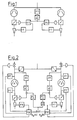
- a fundamentally different route can be followed if the load distribution controller is designed as a three-point step controller in accordance with the circuit diagram in accordance with FIG. 5. If the correction value exceeds the switching threshold set in the step controller, the downstream integrator is moved in the respective direction until the threshold is undershot again.
- the correction variable is added as an additional value to the control differential of the pressure regulator.
- the output of the pressure regulator is also connected to the tracking input of the integrator, the output of the integrator to the tracking input of the controller.
- the correction variable acts on the throttle valve through this regulator.
- the pressure regulator moves its output signal until both the control difference and the correction variable are zero.
- the integrator is switched to tracking at the same time. The step controller is thus ineffective, the integrator follows the pressure controller output without delay.
- the pressure regulator If the pressure regulator is switched off, its output is tracked to the integrator output.
- the integrator is adjusted by the step controller, which thus has a direct influence on the throttle valve position.
- Switching is bumpless, since only one controller or integrator is engaged and the non-leading component is tracked to the output of the other. This also prevents overdriving.
- the pressure regulator is to be switched to automatic, but the load distribution regulator to be manual, the correction quantity must be made zero by a control intervention.
- the time behavior of the load distribution controller can be set either by a clock generator in the output of the step generator or by an adjustable time constant of the integrator.
- step controller instead of the step controller, two limit levels can also be used.
- An asymmetry can be achieved by adding a fixed value to the correction variable.
- inventive method described above can also be used when more than two machines are installed. If only two of a number of machines are in operation, all that has to be done by means of a selection logic is to ensure that the correction variable is switched to the respective controller as the difference between the control differences of the two running machines.
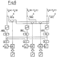
- Figure 6 shows a diagram for switching over with three existing machines.
- the correction values for each possible machine combination are formed (xd (A) - xd (B); xd (B) - xd (C); xd (A) - xd (C)).
- the selection logic must make the correction values of all impermissible combinations zero (switches A&A, B&C and A&C).
- the correction quantity of the selected machine combination is applied in parallel to the two associated pressure regulators. Locking the pressure regulator must ensure that only one pressure regulator can be switched to automatic mode at a time.
- the impermissible combinations are locked by logic stages in the inputs of the load distribution controller.
- each step controller is fed in parallel to the integrators of the two machines, whose control differences occur in the correction variable.
- the number of control commands in the direction of rising control commands is also as large as that in the direction of decreasing for the step controller outputs.
- an average value is formed, which causes exactly the desired control behavior.
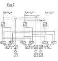
- FIG. 7 shows a circuit diagram for the operation of three machines, the selection circuit and the other machines which are out of operation not being shown.
- PC Pressure regulator
- Pressure regulator B receives and pressure regulator C
- Integrator A receives a + command, integrator B a + and a - command and integrator C a - command.
- this method can also be used on more than three machines.
- the method can also be used if multi-stage machines with intermediate infeed are connected in parallel and a load distribution is required for each infeed (stage).
- FIGS. 8-10 A much simpler circuit than that shown in FIGS. 5 to 7 is shown in FIGS. 8-10.
- a control difference "pressure control”, i. H. Pressure setpoint minus actual pressure value and a control difference load distribution control (balance control) are formed.
- the control difference "load distribution control” contains, analogous to the description, all correction values that are required for the task-related adjustment of the throttle valve. If pressure and load distribution control are switched on, the two control differences add up and the controller is adjusted until the sum of all differences is zero. If a controller is to be switched off, the corresponding input variable is switched to zero by a changeover contact. During such a switchover process, the controller is briefly switched to manual.
- a manual intervention takes place through the manual adjustment input on the pressure regulator.
- a lock must ensure that the balance controllers of all machines operated in parallel must always be switched on together, otherwise operating cases are conceivable in which the control difference of the pressure controller has the same amount but the opposite sign of the control difference of the balance controller. If only one controller is in operation, this can lead to a simulated quasi-calibration. If the parallel load distribution regulator is also engaged, the pressure regulator of which must be switched off, this compensates and frees it from the quasi-adjustment.
- control according to the invention enables the operation of two or even a larger number of turbo compressors in an improved manner and in particular more safely, without the control expenditure being considerable.
Claims (3)
Applications Claiming Priority (2)
| Application Number | Priority Date | Filing Date | Title |
|---|---|---|---|
| US519097 | 1983-08-01 | ||
| US06/519,097 US4560319A (en) | 1983-08-01 | 1983-08-01 | Method and apparatus for controlling at least two parallel-connected turbocompressors |
Publications (3)
| Publication Number | Publication Date |
|---|---|
| EP0132487A2 EP0132487A2 (fr) | 1985-02-13 |
| EP0132487A3 EP0132487A3 (en) | 1986-04-09 |
| EP0132487B1 true EP0132487B1 (fr) | 1988-11-09 |
Family
ID=24066819
Family Applications (1)
| Application Number | Title | Priority Date | Filing Date |
|---|---|---|---|
| EP84100822A Expired EP0132487B1 (fr) | 1983-08-01 | 1984-01-26 | Procédé de régulation d'au moins deux turbo-compresseurs branchés en parallèle |
Country Status (4)
| Country | Link |
|---|---|
| US (1) | US4560319A (fr) |
| EP (1) | EP0132487B1 (fr) |
| JP (1) | JPS6045795A (fr) |
| DE (1) | DE3475094D1 (fr) |
Cited By (1)
| Publication number | Priority date | Publication date | Assignee | Title |
|---|---|---|---|---|
| DE102017211061A1 (de) * | 2017-06-29 | 2019-01-03 | Siemens Aktiengesellschaft | Synchronisierungsverfahren zum Synchronisieren einer Mehrzahl von Aktoren sowie Vorrichtungen zu dessen Durchführung |
Families Citing this family (25)
| Publication number | Priority date | Publication date | Assignee | Title |
|---|---|---|---|---|
| DE3105376C2 (de) * | 1981-02-14 | 1984-08-23 | M.A.N. Maschinenfabrik Augsburg-Nürnberg AG, 4200 Oberhausen | Verfahren zum Betreiben von Turboverdichtern |
| US4640665A (en) * | 1982-09-15 | 1987-02-03 | Compressor Controls Corp. | Method for controlling a multicompressor station |
| DE3540087A1 (de) * | 1985-11-12 | 1987-05-14 | Gutehoffnungshuette Man | Verfahren zum regeln von turbokompressoren |
| DE3540285A1 (de) * | 1985-11-13 | 1987-05-14 | Gutehoffnungshuette Man | Verfahren und einrichtung zum regeln von turbokompressoren |
| DE3620614A1 (de) * | 1986-06-20 | 1987-12-23 | Gutehoffnungshuette Man | Verfahren zum filtern eines verrauschten signals |
| DE3809881A1 (de) * | 1988-03-24 | 1989-10-12 | Gutehoffnungshuette Man | Regelverfahren zur vermeidung des pumpens eines turbokompressors |
| DE3810717A1 (de) * | 1988-03-30 | 1989-10-19 | Gutehoffnungshuette Man | Verfahren zur vermeidung des pumpens eines turboverdichters mittels abblaseregelung |
| DE3935958A1 (de) * | 1989-10-27 | 1991-05-02 | Mtu Muenchen Gmbh | Analoger mehrkanalregler |
| DE3937152A1 (de) * | 1989-11-08 | 1991-05-16 | Gutehoffnungshuette Man | Verfahren zum optimierten betreiben zweier oder mehrerer kompressoren im parallel- oder reihenbetrieb |
| US5306116A (en) * | 1992-04-10 | 1994-04-26 | Ingersoll-Rand Company | Surge control and recovery for a centrifugal compressor |
| US5347467A (en) * | 1992-06-22 | 1994-09-13 | Compressor Controls Corporation | Load sharing method and apparatus for controlling a main gas parameter of a compressor station with multiple dynamic compressors |
| US5743715A (en) * | 1995-10-20 | 1998-04-28 | Compressor Controls Corporation | Method and apparatus for load balancing among multiple compressors |
| US5967761A (en) * | 1997-07-15 | 1999-10-19 | Ingersoll-Rand Company | Method for modulation lag compressor in multiple compressor system |
| DE19828368C2 (de) * | 1998-06-26 | 2001-10-18 | Man Turbomasch Ag Ghh Borsig | Verfahren und Vorrichtung zum Betreiben von zwei- oder mehrstufigen Verdichtern |
| JP4077613B2 (ja) | 2001-05-30 | 2008-04-16 | トヨタ自動車株式会社 | 車輌用制動制御装置 |
| US20070187086A1 (en) * | 2006-02-14 | 2007-08-16 | Anatoly Nikolayevich Ivanov | Device for cutting slot-shaped seats in wells by hydro-sandblasting method |
| US8192171B2 (en) * | 2009-01-15 | 2012-06-05 | Ingersoll-Rand Company | Compressor system |
| US9217370B2 (en) | 2011-02-18 | 2015-12-22 | Dynamo Micropower Corporation | Fluid flow devices with vertically simple geometry and methods of making the same |
| JP5738262B2 (ja) | 2012-12-04 | 2015-06-17 | 三菱重工コンプレッサ株式会社 | 圧縮機制御装置、圧縮機システムおよび圧縮機制御方法 |
| KR102247596B1 (ko) * | 2014-01-24 | 2021-05-03 | 한화파워시스템 주식회사 | 압축기 시스템 및 그 제어 방법 |
| US10030580B2 (en) | 2014-04-11 | 2018-07-24 | Dynamo Micropower Corporation | Micro gas turbine systems and uses thereof |
| DE102016011551B4 (de) * | 2016-09-23 | 2018-05-09 | Mtu Friedrichshafen Gmbh | Brennkraftmaschine |
| RU2660216C1 (ru) * | 2017-07-06 | 2018-07-05 | Общество с ограниченной ответственностью "ГАЗПРОМ ТРАНСГАЗ МОСКВА" | Система автоматического управления газоперекачивающим агрегатом "квант-р" |
| CN110778519B (zh) * | 2019-11-11 | 2021-05-18 | 浙江中控技术股份有限公司 | 一种并联压缩机机组的控制系统 |
| RU2753097C1 (ru) * | 2020-08-25 | 2021-08-11 | Общество с ограниченной ответственностью "Газпром трансгаз Ухта" | Способ заполнения контура агрегата воздушного охлаждения газа |
Family Cites Families (10)
| Publication number | Priority date | Publication date | Assignee | Title |
|---|---|---|---|---|
| GB191126618A (en) * | 1911-11-28 | 1912-07-18 | Karl Baumann | Improvements relating to Centrifugal Blowers. |
| US2993640A (en) * | 1956-05-22 | 1961-07-25 | Oerlikon Engineering Company | Method of and apparatus for maintaining a constant pressure at varying capacity or a constant capacity at variable pressure in a turbo-compressor |
| US3527059A (en) * | 1968-12-26 | 1970-09-08 | Phillips Petroleum Co | Method of controlling parallel-operating refrigeration compressors |
| US3648479A (en) * | 1970-09-28 | 1972-03-14 | Westinghouse Electric Corp | Refrigeration system with multiple centrifugal compressors and load balancing control |
| SU727874A1 (ru) * | 1973-11-27 | 1980-04-15 | Специальное Конструкторское Бюро "Газприборавтоматика" | Система автоматического регулировани давлени на выходе группы совместно работающих компрессоров |
| SU567849A1 (ru) * | 1976-04-12 | 1977-08-05 | Предприятие П/Я А-3513 | Способ противопомпажной защиты группы компрессоров |
| US4139328A (en) * | 1977-05-25 | 1979-02-13 | Gutehoffnungshitte Sterkrade Ag | Method of operating large turbo compressors |
| DE2828124C2 (de) * | 1978-06-27 | 1981-11-19 | M.A.N. Maschinenfabrik Augsburg-Nürnberg AG, 4200 Oberhausen | Verfahren zur Verhinderung des Pumpens von Turboverdichtern |
| DE2852717C2 (de) * | 1978-12-06 | 1982-02-11 | M.A.N. Maschinenfabrik Augsburg-Nürnberg AG, 4200 Oberhausen | Verfahren zur Enddruckbegrenzung für Turbo-Verdichter mittels Abblaseregelung |
| US4255089A (en) * | 1979-03-22 | 1981-03-10 | Dravo Corporation | Method of controlling series fans driving a variable load |
-
1983
- 1983-08-01 US US06/519,097 patent/US4560319A/en not_active Expired - Lifetime
-
1984
- 1984-01-26 DE DE8484100822T patent/DE3475094D1/de not_active Expired
- 1984-01-26 EP EP84100822A patent/EP0132487B1/fr not_active Expired
- 1984-07-18 JP JP59147688A patent/JPS6045795A/ja active Pending
Cited By (1)
| Publication number | Priority date | Publication date | Assignee | Title |
|---|---|---|---|---|
| DE102017211061A1 (de) * | 2017-06-29 | 2019-01-03 | Siemens Aktiengesellschaft | Synchronisierungsverfahren zum Synchronisieren einer Mehrzahl von Aktoren sowie Vorrichtungen zu dessen Durchführung |
Also Published As
| Publication number | Publication date |
|---|---|
| JPS6045795A (ja) | 1985-03-12 |
| EP0132487A2 (fr) | 1985-02-13 |
| DE3475094D1 (en) | 1988-12-15 |
| US4560319A (en) | 1985-12-24 |
| EP0132487A3 (en) | 1986-04-09 |
Similar Documents
| Publication | Publication Date | Title |
|---|---|---|
| EP0132487B1 (fr) | Procédé de régulation d'au moins deux turbo-compresseurs branchés en parallèle | |
| DE69728254T2 (de) | Regelsystem für dynamische kompressoren zur verhinderung des wiederauftretens des pumpens | |
| EP1134422A2 (fr) | Procédé pour le contrôle de pompage d' un turbo-compresseur | |
| EP0058305B1 (fr) | Commande de turbo-compresseurs pour éviter le pompage | |
| DE2828124C2 (de) | Verfahren zur Verhinderung des Pumpens von Turboverdichtern | |
| DE19828368C2 (de) | Verfahren und Vorrichtung zum Betreiben von zwei- oder mehrstufigen Verdichtern | |
| CH648639A5 (de) | Verfahren zur regelung des abblasens eines turbo-verdichters. | |
| DE10208676A1 (de) | Verfahren zum Regeln von mehreren Strömungsmaschinen im Parallel- oder Reihenbetrieb | |
| EP0066651A2 (fr) | Procédé et appareil pour commander un turbogénérateur | |
| DE2025528C3 (de) | Regeleinrichtung für eine Dampfturbinen-Kraftanlage | |
| DE3037780C2 (de) | Verfahren und Anordnung zum Regeln des Betriebes einer Entnahmeturbine | |
| EP1016787A2 (fr) | Procédé d' opération d' un compresseur et système fonctionnant selon ce procédé | |
| EP0335105B1 (fr) | Procédé pour éviter le pompage d'un compresseur centrifuge par le contrôle d'échappement | |
| EP0334034B1 (fr) | Procédé de commande pour éviter le pompage d'un compresseur centrifuge | |
| EP1116885B1 (fr) | Procédé et appareil de contrôle d'un turbo-compresseur pour éviter le pompage | |
| CH679235A5 (fr) | ||
| CH619509A5 (fr) | ||
| EP0822332B1 (fr) | Générateur hydraulique | |
| EP0544615B1 (fr) | Méthode de fonctionnement d'un générateur de vapeur à passage unique et à recirculation à faible charge | |
| DE2735246A1 (de) | Regeleinrichtung fuer einen turboverdichter | |
| EP0757180A1 (fr) | Procédé et dispositif d'opération des turbomachines avec régulateurs à gain proportionnel élevé | |
| DE2638456C3 (de) | Verfahren zum Anfahren von Regelkreisen | |
| DE4292022C2 (de) | Steuersystem zum Abzapfen von Dampf aus und/oder Injizieren in eine Turbine | |
| DE2516379A1 (de) | Anordnung zur steuerung der ausgangsleistung eines oder mehrerer turbogeneratoren in einem kraftwerk | |
| DE19828446C1 (de) | Verfahren zur koordinierten Regelung eines Dampfkraftwerksblockes |
Legal Events
| Date | Code | Title | Description |
|---|---|---|---|
| PUAI | Public reference made under article 153(3) epc to a published international application that has entered the european phase |
Free format text: ORIGINAL CODE: 0009012 |
|
| AK | Designated contracting states |
Designated state(s): CH DE FR GB IT LI NL |
|
| 17P | Request for examination filed |
Effective date: 19850201 |
|
| PUAL | Search report despatched |
Free format text: ORIGINAL CODE: 0009013 |
|
| AK | Designated contracting states |
Kind code of ref document: A3 Designated state(s): CH DE FR GB IT LI NL |
|
| RAP1 | Party data changed (applicant data changed or rights of an application transferred) |
Owner name: MAN GUTEHOFFNUNGSHUETTE GMBH |
|
| 17Q | First examination report despatched |
Effective date: 19861031 |
|
| GRAA | (expected) grant |
Free format text: ORIGINAL CODE: 0009210 |
|
| AK | Designated contracting states |
Kind code of ref document: B1 Designated state(s): CH DE FR GB IT LI NL |
|
| ITF | It: translation for a ep patent filed |
Owner name: BARZANO' E ZANARDO MILANO S.P.A. |
|
| REF | Corresponds to: |
Ref document number: 3475094 Country of ref document: DE Date of ref document: 19881215 |
|
| GBT | Gb: translation of ep patent filed (gb section 77(6)(a)/1977) | ||
| ET | Fr: translation filed | ||
| RAP2 | Party data changed (patent owner data changed or rights of a patent transferred) |
Owner name: MAN GUTEHOFFNUNGSHUETTE AKTIENGESELLSCHAFT |
|
| NLT2 | Nl: modifications (of names), taken from the european patent patent bulletin |
Owner name: MAN GUTEHOFFNUNGSHUETTE AKTIENGESELLSCHAFT TE OBER |
|
| PLBE | No opposition filed within time limit |
Free format text: ORIGINAL CODE: 0009261 |
|
| STAA | Information on the status of an ep patent application or granted ep patent |
Free format text: STATUS: NO OPPOSITION FILED WITHIN TIME LIMIT |
|
| 26N | No opposition filed | ||
| ITTA | It: last paid annual fee | ||
| REG | Reference to a national code |
Ref country code: GB Ref legal event code: 732E |
|
| REG | Reference to a national code |
Ref country code: CH Ref legal event code: PFA Free format text: MAN GUTEHOFFNUNGSHUETTE GMBH TRANSFER- MAN GUTEHOFFNUNGSHUETTE AKTIENGESELLSCHAFT Ref country code: CH Ref legal event code: PUE Owner name: MAN GUTEHOFFNUNGSHUETTE AKTIENGESELLSCHAFT -DANN A |
|
| NLS | Nl: assignments of ep-patents |
Owner name: GHH BORSIG TURBOMASCHINEN GMBH;MAN GUTEHOFFNUNGSHU |
|
| REG | Reference to a national code |
Ref country code: FR Ref legal event code: TP |
|
| REG | Reference to a national code |
Ref country code: FR Ref legal event code: CD Ref country code: FR Ref legal event code: CA Ref country code: FR Ref legal event code: CJ |
|
| REG | Reference to a national code |
Ref country code: GB Ref legal event code: IF02 |
|
| PGFP | Annual fee paid to national office [announced via postgrant information from national office to epo] |
Ref country code: CH Payment date: 20021218 Year of fee payment: 20 |
|
| PGFP | Annual fee paid to national office [announced via postgrant information from national office to epo] |
Ref country code: GB Payment date: 20021227 Year of fee payment: 20 Ref country code: NL Payment date: 20021227 Year of fee payment: 20 |
|
| PGFP | Annual fee paid to national office [announced via postgrant information from national office to epo] |
Ref country code: FR Payment date: 20030110 Year of fee payment: 20 |
|
| PGFP | Annual fee paid to national office [announced via postgrant information from national office to epo] |
Ref country code: DE Payment date: 20030124 Year of fee payment: 20 |
|
| PG25 | Lapsed in a contracting state [announced via postgrant information from national office to epo] |
Ref country code: LI Free format text: LAPSE BECAUSE OF EXPIRATION OF PROTECTION Effective date: 20040125 Ref country code: CH Free format text: LAPSE BECAUSE OF EXPIRATION OF PROTECTION Effective date: 20040125 Ref country code: GB Free format text: LAPSE BECAUSE OF EXPIRATION OF PROTECTION Effective date: 20040125 |
|
| PG25 | Lapsed in a contracting state [announced via postgrant information from national office to epo] |
Ref country code: NL Free format text: LAPSE BECAUSE OF EXPIRATION OF PROTECTION Effective date: 20040126 |
|
| REG | Reference to a national code |
Ref country code: GB Ref legal event code: PE20 |
|
| REG | Reference to a national code |
Ref country code: CH Ref legal event code: PL |
|
| NLV7 | Nl: ceased due to reaching the maximum lifetime of a patent |
Effective date: 20040126 |