EP0132487B1 - Process for controlling at least two turbo compressors mounted in parallel - Google Patents
Process for controlling at least two turbo compressors mounted in parallel Download PDFInfo
- Publication number
- EP0132487B1 EP0132487B1 EP84100822A EP84100822A EP0132487B1 EP 0132487 B1 EP0132487 B1 EP 0132487B1 EP 84100822 A EP84100822 A EP 84100822A EP 84100822 A EP84100822 A EP 84100822A EP 0132487 B1 EP0132487 B1 EP 0132487B1
- Authority
- EP
- European Patent Office
- Prior art keywords
- control
- pressure
- compressors
- controller
- blow
- Prior art date
- Legal status (The legal status is an assumption and is not a legal conclusion. Google has not performed a legal analysis and makes no representation as to the accuracy of the status listed.)
- Expired
Links
Images


Classifications
-
- F—MECHANICAL ENGINEERING; LIGHTING; HEATING; WEAPONS; BLASTING
- F04—POSITIVE - DISPLACEMENT MACHINES FOR LIQUIDS; PUMPS FOR LIQUIDS OR ELASTIC FLUIDS
- F04D—NON-POSITIVE-DISPLACEMENT PUMPS
- F04D27/00—Control, e.g. regulation, of pumps, pumping installations or pumping systems specially adapted for elastic fluids
- F04D27/02—Surge control
- F04D27/0253—Surge control by throttling
-
- F—MECHANICAL ENGINEERING; LIGHTING; HEATING; WEAPONS; BLASTING
- F04—POSITIVE - DISPLACEMENT MACHINES FOR LIQUIDS; PUMPS FOR LIQUIDS OR ELASTIC FLUIDS
- F04D—NON-POSITIVE-DISPLACEMENT PUMPS
- F04D27/00—Control, e.g. regulation, of pumps, pumping installations or pumping systems specially adapted for elastic fluids
- F04D27/02—Surge control
- F04D27/0269—Surge control by changing flow path between different stages or between a plurality of compressors; load distribution between compressors
Definitions
- the invention relates to a method for operating at least two turbocompressors connected in parallel, each of which is provided with a surge limit control to prevent pumping, i. H. that before reaching the surge limit when reaching a blow-off line running parallel to this, opening blow-off or blow-off valves ensures that pumping is avoided, and the turbo-compressors are also controlled jointly by load distribution regulators and individually by a pressure regulator.
- Each flow controller has the same setpoint (output of the pressure controller) and consequently leads each machine to the operating point at which it is operated with the same throughput as the parallel machine (s).
- the parallel machine s
- a typical suitable surge limit control is e.g. B. described in D-A 2 623 899. On the basis of a correspondingly increasing control characteristic curve, it ensures that a blow-off takes place in time so that pumping is reliably prevented.
- the surge limit control is initially set in a stable manner.
- the flow control must then react much more slowly to avoid repercussions.
- the pressure control as a superimposed master control must in turn react much more slowly.
- the load distribution control has the task of preventing operating states in which one machine is blowing off while other machines or another machine are driving far in the map. A regulation for setting the same flow cannot fully accomplish this task. So z. B. asymmetries in the course of the characteristic curves or the blow-off lines, as described above, are compensated for just as little as the influence of different suction pressures or an asymmetrical flow course in the pipelines.
- turbocompressors should be able to be operated under the most favorable conditions, taking into account their individual values, and they should be able to be adapted to possible pressure and flow fluctuations as quickly as possible, the entire control system being supposed to be safe, prone to failure and economical. In particular, the entire regulation should be able to be implemented using commercially available components.
- the load distribution regulators regulate the setting of the compressors with one another in such a way that the operating point is at the same distance from the blow-off line, with only one of the compressors being controlled by its pressure regulator and the rest via the pressure regulator Load distribution control are tracked, in which the pressure regulator is set to automatic by its pressure regulator-controlled compressor, while the pressure regulators of the other compressors are set to manual operation and a control difference between the pressure control and the load distribution control is formed, these control differences are added and there is a comparison, until the sum of the differences is zero. This also ensures that there is also an optimal distance of the working points from the blow-off line in the control phase.
- each compressor has its own pressure control, which acts directly on the throttle valve.
- the pressure control can thus be made in the time behavior as quickly as in the known system of the flow controller.
- the pressure regulators are interlocked in such a way that only a maximum of one pressure regulator can be switched to automatic.
- the other or the other is or are switched to hand, i. H. passive as long as there is no manual intervention.
- FC parallel load distribution controller
- This variable is identical to the control difference x d of the surge limit control (FSC) and is available there as a signal, so it does not need to be determined or measured separately.
- the determination of such a signal goes z. B. from German patent application P 26 23 899.3, in which a corresponding pressure-flow diagram is shown, which contains a surge line and blow-off line and operating curves of turbo compressors. Otherwise, the terms mentioned are generally known to the person skilled in the art.
- the control difference of one machine (xd (A)) is different than that of the other machine (xd (B)).
- the difference between these two quantities is applied as a correction quantity (actual value) to the two load distribution controllers, with a different sign.
- the setpoint of these controllers is usually set to zero, but it can also assume other values if an asymmetry is desired.
- the output of the load distribution controller has an additive effect on the output of the pressure controller. If there is a different load on the machines, one load distribution controller continues to open the throttle valve, while the other closes the flap of the parallel machine (s) to the same extent. Assuming linear characteristics of the throttle valves, the overall throughput of the machines and thus the final pressure are not influenced by this control process. In a real system, the pressure regulator only needs to readjust the asymmetries of the throttle valves.
- the pressure controller first tracks the machine that is set to automatic. The resulting asymmetry in the machine load is detected by the load distribution controller, which then adjusts all machines until the symmetry is reached again.
- FIG. 3 shows such a tracking circuit. Controllers are used whose output size can be limited to an externally adjustable value. Overdriving is prevented if the output of each controller is limited to a variable that corresponds to the difference between the other manipulated variable and 100%.
- Another possibility is to always prevent the further increase in the two manipulated variables when the throttle valve has reached its end position.
- this can be achieved either by appropriate wiring of the controllers, but also according to the circuit diagram corresponding to FIG. 4 by a maximum selection in front of each controller.
- An amplifier is used in order to maintain sufficient controller dynamics even with manipulated variables close to 100% and to avoid impermissible limitation of the control differences for pressure regulators and load distribution regulators.
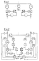
- a fundamentally different route can be followed if the load distribution controller is designed as a three-point step controller in accordance with the circuit diagram in accordance with FIG. 5. If the correction value exceeds the switching threshold set in the step controller, the downstream integrator is moved in the respective direction until the threshold is undershot again.
- the correction variable is added as an additional value to the control differential of the pressure regulator.
- the output of the pressure regulator is also connected to the tracking input of the integrator, the output of the integrator to the tracking input of the controller.
- the correction variable acts on the throttle valve through this regulator.
- the pressure regulator moves its output signal until both the control difference and the correction variable are zero.
- the integrator is switched to tracking at the same time. The step controller is thus ineffective, the integrator follows the pressure controller output without delay.
- the pressure regulator If the pressure regulator is switched off, its output is tracked to the integrator output.
- the integrator is adjusted by the step controller, which thus has a direct influence on the throttle valve position.
- Switching is bumpless, since only one controller or integrator is engaged and the non-leading component is tracked to the output of the other. This also prevents overdriving.
- the pressure regulator is to be switched to automatic, but the load distribution regulator to be manual, the correction quantity must be made zero by a control intervention.
- the time behavior of the load distribution controller can be set either by a clock generator in the output of the step generator or by an adjustable time constant of the integrator.
- step controller instead of the step controller, two limit levels can also be used.
- An asymmetry can be achieved by adding a fixed value to the correction variable.
- inventive method described above can also be used when more than two machines are installed. If only two of a number of machines are in operation, all that has to be done by means of a selection logic is to ensure that the correction variable is switched to the respective controller as the difference between the control differences of the two running machines.
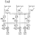
- Figure 6 shows a diagram for switching over with three existing machines.
- the correction values for each possible machine combination are formed (xd (A) - xd (B); xd (B) - xd (C); xd (A) - xd (C)).
- the selection logic must make the correction values of all impermissible combinations zero (switches A&A, B&C and A&C).
- the correction quantity of the selected machine combination is applied in parallel to the two associated pressure regulators. Locking the pressure regulator must ensure that only one pressure regulator can be switched to automatic mode at a time.
- the impermissible combinations are locked by logic stages in the inputs of the load distribution controller.
- each step controller is fed in parallel to the integrators of the two machines, whose control differences occur in the correction variable.
- the number of control commands in the direction of rising control commands is also as large as that in the direction of decreasing for the step controller outputs.
- an average value is formed, which causes exactly the desired control behavior.
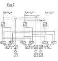
- FIG. 7 shows a circuit diagram for the operation of three machines, the selection circuit and the other machines which are out of operation not being shown.
- PC Pressure regulator
- Pressure regulator B receives and pressure regulator C
- Integrator A receives a + command, integrator B a + and a - command and integrator C a - command.
- this method can also be used on more than three machines.
- the method can also be used if multi-stage machines with intermediate infeed are connected in parallel and a load distribution is required for each infeed (stage).
- FIGS. 8-10 A much simpler circuit than that shown in FIGS. 5 to 7 is shown in FIGS. 8-10.
- a control difference "pressure control”, i. H. Pressure setpoint minus actual pressure value and a control difference load distribution control (balance control) are formed.
- the control difference "load distribution control” contains, analogous to the description, all correction values that are required for the task-related adjustment of the throttle valve. If pressure and load distribution control are switched on, the two control differences add up and the controller is adjusted until the sum of all differences is zero. If a controller is to be switched off, the corresponding input variable is switched to zero by a changeover contact. During such a switchover process, the controller is briefly switched to manual.
- a manual intervention takes place through the manual adjustment input on the pressure regulator.
- a lock must ensure that the balance controllers of all machines operated in parallel must always be switched on together, otherwise operating cases are conceivable in which the control difference of the pressure controller has the same amount but the opposite sign of the control difference of the balance controller. If only one controller is in operation, this can lead to a simulated quasi-calibration. If the parallel load distribution regulator is also engaged, the pressure regulator of which must be switched off, this compensates and frees it from the quasi-adjustment.
- control according to the invention enables the operation of two or even a larger number of turbo compressors in an improved manner and in particular more safely, without the control expenditure being considerable.
Description
Die Erfindung betrifft ein Verfahren zum Betreiben von mindestens zwei parallel geschalteten Turbokompressoren, die jeweils zur Verhinderung des Pumpens mit einer Pumpgrenzregelung versehen sind, d. h. daß bei ihnen vor Erreichen der Pumpgrenze beim Erreichen einer zu dieser parallel verlaufenden Abblaselinie durch Öffnen von Abblase- oder Umblaseventilen sichergestellt wird, daß ein Pumpen vermieden wird, und wobei die Turbokompressoren außerdem gemeinsam von Lastverteilungsreglern und einzeln von je einem Duckregler gesteuert werden.The invention relates to a method for operating at least two turbocompressors connected in parallel, each of which is provided with a surge limit control to prevent pumping, i. H. that before reaching the surge limit when reaching a blow-off line running parallel to this, opening blow-off or blow-off valves ensures that pumping is avoided, and the turbo-compressors are also controlled jointly by load distribution regulators and individually by a pressure regulator.
Bei Kompressoren im Parallelbetrieb besteht häufig die Aufgabe, die Last gleichmäßig auf alle Maschinen zu verteilen. Üblicherweise wird diese Aufgabe dadurch gelöst, daß jeder Maschine ein Durchflußregler zugeordnet wird. Der Sollwert dieser Durchflußregler wird von einem gemeinsamen übergeordneten Druckregler vorgegeben.With compressors in parallel operation, the task is often to distribute the load evenly across all machines. This task is usually solved by assigning a flow controller to each machine. The setpoint of these flow regulators is specified by a common higher-level pressure regulator.
Jeder Durchflußregler hat den gleichen Sollwert (Ausgang des Druckreglers) und führt infolgedessen jede Maschine in den Arbeitspunkt, in dem sie mit dem gleichen Durchsatz betrieben wird wie die Parallelmaschine(n). Bei unterschiedlichen Kennlinien der Maschinen ist es dabei nachteilig möglich, daß dabei eine Maschine im Abblase- oder Umblasebetrieb gefahren wird, während die andere weit im Kennfeld fährt. Diese Gefahr ist bei Maschinen mit flachen Kennlinien besonders groß.Each flow controller has the same setpoint (output of the pressure controller) and consequently leads each machine to the operating point at which it is operated with the same throughput as the parallel machine (s). In the case of different characteristic curves of the machines, it is disadvantageously possible for one machine to be operated in the blow-off or blow-around mode while the other is traveling far in the map. This danger is particularly great for machines with flat characteristic curves.
Diese Anordnung hat außerdem den Nachteil, daß der Durchflußregler in Kaskade zum Druckregler arbeitet.This arrangement also has the disadvantage that the flow regulator works in cascade with the pressure regulator.
Bleibende Regelfehler müssen dabei vermieden werden, so daß beide Regler als Pl-Regler zu schalten sind. Eine Reihenschaltung von zwei PI-Reglern kann aber bekanntlich nur dann stabil arbeiten, wenn der vorgeschaltete Regler wesentlich langsamer arbeitet als der unterlagerte. Da Turbokompressoren in der Regel auch noch mit Pumpgrenzregelungen ausgerüstet sind, die ebenfalls PI-Verhalten haben, bestimmen diese das Zeitverhalten aller Regelungen.Permanent control errors must be avoided so that both controllers are to be switched as PI controllers. As is well known, a series connection of two PI controllers can only work stably if the upstream controller works much slower than the lower one. Since turbo compressors are usually also equipped with surge limit controls that also have PI behavior, these determine the timing of all controls.
Eine typische geeignete Pumpgrenzregelung ist z. B. in der D-A 2 623 899 beschrieben. Sie stellt aufgrund einer entsprechend ansteigenden Regelkennlinie sicher, daß ein Abblasen so rechtzeitig erfolgt, daß ein Pumpen sicher verhindert wird.A typical suitable surge limit control is e.g. B. described in D-A 2 623 899. On the basis of a correspondingly increasing control characteristic curve, it ensures that a blow-off takes place in time so that pumping is reliably prevented.
In der Praxis wird dabei die Pumpgrenzregelung erst einmal stabil eingestellt. Die Durchflußregelung muß dann wesentlich langsamer reagieren, um Rückwirkungen zu vermeiden. Die Druckregelung als überlagerte Führungsregelung muß wiederum noch wesentlich langsamer reagieren. Die Folge ist, daß der Druckregler Störungen nur relativ langsam ausregeln kann. Die Lastverteilungsregelung hat in diesem Zusammenhang die Aufgabe, Betriebszustände zu verhindern, in denen eine Maschine abbläst, während andere Maschinen oder eine andere Maschine weit im Kennfeld fahren. Eine Regelung zur Einstellung von gleichem Durchfluß kann diese Aufgabe nicht vollständit erfüllen. So können z. B. Unsymmetrien im Verlauf der Kennlinien bzw. der Abblaselinien, wie oben beschrieben, genausowenig kompensiert werden wie der Einfluß unterschiedlicher Saugdrück oder ein unsymmetrischer Strömungsverlauf in den Rohrleitungen.In practice, the surge limit control is initially set in a stable manner. The flow control must then react much more slowly to avoid repercussions. The pressure control as a superimposed master control must in turn react much more slowly. The result is that the pressure regulator can only correct faults relatively slowly. In this context, the load distribution control has the task of preventing operating states in which one machine is blowing off while other machines or another machine are driving far in the map. A regulation for setting the same flow cannot fully accomplish this task. So z. B. asymmetries in the course of the characteristic curves or the blow-off lines, as described above, are compensated for just as little as the influence of different suction pressures or an asymmetrical flow course in the pipelines.
Es ist demgemäß Aufgabe der Erfindung, ein Verfahren zum Betreiben bzw. Regeln von parallelgeschalteten Turbokompressoren zu finden, dem die Vorgenannten Nachteile nicht mehr anhaften und das es insbesondere erlaubt, sämtliche Turbokompressoren während des Betriebes im ausreichenden Abstand von der Abblaselinie zu betreiben, so daß ein überflüssiges Abblasen einerseits sicher vermieden wird, andererseits aber auch eine möglichst große Sicherheit gegen Pumpen vorhanden ist.It is accordingly an object of the invention to find a method for operating or regulating turbocompressors connected in parallel, which no longer has the aforementioned disadvantages and which in particular allows all turbocompressors to be operated at a sufficient distance from the blow-off line during operation, so that a unnecessary blowing is reliably avoided on the one hand, but on the other hand there is also the greatest possible security against pumps.
Die Turbokompressoren sollen dabei unter Berücksichtigung ihrer individuellen Werte unter möglichst günstigen Bedingungen betrieben werden können, sie sollen möglichen Druck- und Druchflußschwankungen mölichst schnell angepaßt werden können, wobei die gesamte Regelung sicher, störungsanfällig und wirtschaftlich sein soll. Insbesondere soll die gesamte Regelung mit handelsüblichen Bauelementen verwirklichbar sein.The turbocompressors should be able to be operated under the most favorable conditions, taking into account their individual values, and they should be able to be adapted to possible pressure and flow fluctuations as quickly as possible, the entire control system being supposed to be safe, prone to failure and economical. In particular, the entire regulation should be able to be implemented using commercially available components.
Diese Aufgabenstellung soll weiterhin gelöst werden unter dem neuartigen Gesichtspunkt, daß insbesondere ein Abblasen oder Pumpen einzelner Kompressoren vermieden werden soll, da dadurch Belästigungen z. B. durch Lärm, Wirkungsgradverluste erheblicher Größe und unter Umständen auch Schäden auftreten können.This task should continue to be solved from the new point of view that in particular blowing or pumping individual compressors should be avoided, as this would cause annoyances such. B. by noise, loss of efficiency of considerable size and, under certain circumstances, damage can occur.
Diese Aufgabe wird erfindungsgemäß bei dem eingangs genannten Verfahren dadurch gelöst, daß die Lastverteilungsregler die Einstellung der Kompressoren untereinander derart regeln, daß bei jedem gleiche Abstände des Betriebspunktes gegenüber der Abblaselinie vorliegen, wobei nur einer der Kompressoren von seinem Druckregler gesteuert wird und die übrigen über die Lastverteilungsregelung nachgeführt werden, bei dem von seinem Druckregler gesteuerten Kompressor der Druckregler auf Automatik gestellt wird, während die Druckregler der andere Kompressoren auf Handbetrieb eingestellt werden und je eine Regeldifferenz der Druckregelung und der Lastverteilungsregelung gebildet wird, diese Regeldifferenzen addiert werden und ein Abgleich solange erfolgt, bis die Summe der Differenzen Null ist. Dadurch wird auch sichergestellt, daß auch in der Regelphase ein optimaler Abstand der Arbeitspunkte von der Abblaselinie vorhanden ist.This object is achieved in the above-mentioned method in that the load distribution regulators regulate the setting of the compressors with one another in such a way that the operating point is at the same distance from the blow-off line, with only one of the compressors being controlled by its pressure regulator and the rest via the pressure regulator Load distribution control are tracked, in which the pressure regulator is set to automatic by its pressure regulator-controlled compressor, while the pressure regulators of the other compressors are set to manual operation and a control difference between the pressure control and the load distribution control is formed, these control differences are added and there is a comparison, until the sum of the differences is zero. This also ensures that there is also an optimal distance of the working points from the blow-off line in the control phase.
Weitere vorteilhafte Ausbildungen der Erfindung werden in den Unteransprüchen 2 und 3 beschrieben.Further advantageous embodiments of the invention are described in subclaims 2 and 3.
Im folgenden wird ein Aushührungsbeispiel der Erfindung anhand von Zeichnungen näher beschrieben. Es zeigen:
Figur 1 eine Kaskadenregelung herkömmlicher Art nach dem Stand der Technik,- Figur 2 eine Lastverteilungsregelung gemäß der Erfindung,
- Figur 3 eine Nachführschaltung gemäß der Erfindung, zur Begrenzung der Reglerausgänge,
- Figur 4 eine Endlagenbegrenzung gemäß der Erfindung,
- Figur 5 eine Lastverteilungsregelung in Form eines Schrittreglers,
- Figur 6 eine erfindungsmegäße Schaltung zum Parallelbetrieb von jeweils zwei von drei vorhandenen Maschinen,
- Figur 7 die Schaltung für den Parallelbetrieb von drei Maschinen,
- Figur 8 eine Lastverteilungsregelung mit nur einem Druckregler,
- Figur 9 eine Schaltung zum Parallelbetrieb zweier von drei Kompressoren und
Figur 10 eine Schaltung zum Parallelbetrieb von drei Kompressoren.
- FIG. 1 shows a conventional type of cascade control according to the prior art,
- FIG. 2 shows a load distribution control according to the invention,
- 3 shows a tracking circuit according to the invention, for limiting the controller outputs,
- FIG. 4 an end position limitation according to the invention,
- FIG. 5 shows a load distribution control in the form of a step controller,
- FIG. 6 shows a circuit according to the invention for parallel operation of two out of three existing machines,
- 7 shows the circuit for the parallel operation of three machines,
- FIG. 8 shows a load distribution control with only one pressure regulator,
- Figure 9 shows a circuit for operating two of three compressors in parallel
- Figure 10 shows a circuit for the parallel operation of three compressors.
Gemäß Figur 2 besitzt jeder Kompressor eine eigene Druckregelung, die direkt auf die Drosselklappe wirkt. Die Druckregelung kann dadurch im Zeitverhalten so schnell gemacht werden, wie im bekannten System der Durchflußregler.According to Figure 2, each compressor has its own pressure control, which acts directly on the throttle valve. The pressure control can thus be made in the time behavior as quickly as in the known system of the flow controller.
Die Druckregler sind derart gegeneinander verriegelt, daß nur maximal ein Druckregler auf Automatik geschaltet sein kann. Der andere bzw. die anderen ist bzw. sind auf Hand geschaltet, d. h. passiv, solange kein Handeingriff erfolgt.The pressure regulators are interlocked in such a way that only a maximum of one pressure regulator can be switched to automatic. The other or the other is or are switched to hand, i. H. passive as long as there is no manual intervention.
Die Lastverteilung wird durch je einen parallelen Lastverteilungsregler (FC) erreicht. Dieser Regler erhält erfindungswesentlich als Istwert nicht den Durchfluß, sondern den Abstand des Arbeitspunktes der Maschine von der Abblaselinie (gemessen im Druck-Durchflußdiagramm).The load distribution is achieved by a parallel load distribution controller (FC). Essential to the invention, this controller does not receive the flow as the actual value, but rather the distance between the working point of the machine and the blow-off line (measured in the pressure-flow diagram).
Diese Größe ist identisch mit der Regeldifferenz xd der Pumpgrenzregelung (FSC) und steht dort als Signal zur Verfügung, braucht also nicht gesondert bestimmt oder gemessen werden. Die Bestimmung eines solchen Signals geht z. B. aus der deutschen Patentanmeldung P 26 23 899.3 hervor, in welcher auch ein entsprechendes Druck-Durch-flußdiagramm gezeigt wird, welches eine Pumpgrenz- und Abblaselinie sowie Betriebskurven von Turbokompressoren enthält. Im übrigen sind die geannten Begriffe dem Fachmann allgemein bekannt.This variable is identical to the control difference x d of the surge limit control (FSC) and is available there as a signal, so it does not need to be determined or measured separately. The determination of such a signal goes z. B. from German patent application P 26 23 899.3, in which a corresponding pressure-flow diagram is shown, which contains a surge line and blow-off line and operating curves of turbo compressors. Otherwise, the terms mentioned are generally known to the person skilled in the art.
Bei einer unsymmetrischen Belastung der Maschinen ist die Regeldifferenz der einen Maschine (xd(A)) anders als die der anderen Maschine (xd(B)). Die Differenz dieser beiden Größen wird als Korrekturgröße (Istwert) den beiden Lastverteilungsreglern aufgeschaltet, und zwar mit unterschiedlichen Vorzeichen. Der Sollwert dieser Regler ist in der Regel auf Null gestellt, er kann jedoch auch andere Werte annehmen, wenn eine Unsymmetrie gewünscht ist.With an asymmetrical load on the machines, the control difference of one machine (xd (A)) is different than that of the other machine (xd (B)). The difference between these two quantities is applied as a correction quantity (actual value) to the two load distribution controllers, with a different sign. The setpoint of these controllers is usually set to zero, but it can also assume other values if an asymmetry is desired.
Der Ausgang der Lastverteilungsregler wirkt additiv auf den Ausgang der Druckregler. Bei einer vorhandenen unterschiedlichen Belastung der Maschinen fährt der eine Lastverteilungsregler die Drosselklappe weiter auf, während der andere die Klappe der Parallelmaschine(n) im gleichen Maße schließt. Setzt man lineare Kennlinien der Drosselklappen voraus, wird durch diesen Regelvorgang der Gesamtdurchsatz der Maschinen und damit der Enddruck nicht beeinfulßt. Bei einer realen Anlage braucht der Druckregler nur die Unsymmetrien der Drosselklappen nachregeln.The output of the load distribution controller has an additive effect on the output of the pressure controller. If there is a different load on the machines, one load distribution controller continues to open the throttle valve, while the other closes the flap of the parallel machine (s) to the same extent. Assuming linear characteristics of the throttle valves, the overall throughput of the machines and thus the final pressure are not influenced by this control process. In a real system, the pressure regulator only needs to readjust the asymmetries of the throttle valves.
Da Druckregler und Lastverteilungsregler dadurch bereits systembedingt entkoppelt sind, können beide gleiches Zeitverhalten erhalten. Bei einer Änderung des Enddruckes führt der Druckregler zunächst die Maschine nach, die auf Automatik steht. Die dadurch bedingte Unsymmetrie in der Maschinenbelastung wird vom Lastverteilungsregeler erfaßt, der anschließend alle Maschinen soweit nachführt, bis die Symmetrie wieder erreicht ist.Since the pressure regulator and load distribution regulator are already decoupled due to the system, they can both have the same time behavior. If the final pressure changes, the pressure controller first tracks the machine that is set to automatic. The resulting asymmetry in the machine load is detected by the load distribution controller, which then adjusts all machines until the symmetry is reached again.
Im Betrieb der Kompressoren werden gemäß Figur 2 die Ausgänge von Druckregler und Lastverteilungsregler addiert. Dadurch kann diese Summe, d. h. die Stellgröße der Drosselklappe, Werte zwischen 0 und 200% der Nenngröße annehmen. Da die Klappe bereits bei 100% die Endlage erreicht, kann eine erhebliche Übersteuerung eintreten. Dies ist unerwünscht und kann zu erheblichen Betriebsstörungen führen.In the operation of the compressors, the outputs of the pressure regulator and the load distribution regulator are added according to FIG. This allows this sum, i.e. H. the manipulated variable of the throttle valve, take values between 0 and 200% of the nominal size. Since the flap already reaches the end position at 100%, considerable oversteer can occur. This is undesirable and can lead to considerable malfunctions.
Um dies zu verhindern, kann eine Schaltung gemäß Figur 3 eingesetzt werden. Figur 3 zeigt eine solche Nachführschaltung. Es werden Regler eingesetzt, deren Ausgangsgröße auf einen extern einstellbaren Wert begrenzt werden kann. Eine Übersteuerung wird dann verhindert, wenn der Ausgang eines jeden Reglers auf eine Größe begrenzt wird, die der Differenz aus der anderen Stellgröße und 100% entspricht.To prevent this, a circuit according to FIG. 3 can be used. Figure 3 shows such a tracking circuit. Controllers are used whose output size can be limited to an externally adjustable value. Overdriving is prevented if the output of each controller is limited to a variable that corresponds to the difference between the other manipulated variable and 100%.
Eine andere Möglichkeit besteht darin, den weiteren Anstieg der beiden Stellgrößen stets dann zu verhindern, wenn die Drosselklappe ihre Endlage erreicht hat. Technisch kann dies entweder durch eine entsprechende Beschaltung der Regler, aber auch gemäß dem Schaltschema entsprechend Figur 4 durch eine Maximalauswahl vor jedem Regler erreicht werden.Another possibility is to always prevent the further increase in the two manipulated variables when the throttle valve has reached its end position. Technically, this can be achieved either by appropriate wiring of the controllers, but also according to the circuit diagram corresponding to FIG. 4 by a maximum selection in front of each controller.
Um auch bei Stellgrößen nahe 100% noch eine ausreichende Reglerdynamik zu erhalten und keine unzulässige Begrenzung der Regeldifferenzen für Druckregler und Lastverteilungsregler zu erhalten, wird ein Verstärker eingesetzt.An amplifier is used in order to maintain sufficient controller dynamics even with manipulated variables close to 100% and to avoid impermissible limitation of the control differences for pressure regulators and load distribution regulators.
Die gleiche Funktion läßt sich auch erreichen, wenn den Maximalauswahlgeräten bei Erreichen der Endlage (gemeldet durch einen Endschalter oder eine Grenzwertstufe an der Stellgrößensumme) ein Wert null aufgeschaltet wird, während in allen anderen Fällen 100% vorgegeben werden.The same function can also be achieved if a maximum value of zero is applied to the maximum selection devices when the end position is reached (reported by a limit switch or a limit value step at the manipulated variable sum), whereas in all
Ein grundsätzlich anderer Weg kann beschritten werden, wenn gemäß dem Schaltschema entsprechend Figur 5 der Lastverteilungsregler als Dreipunkt-Schrittregler ausgeführt wird. Übersteigt die Korrekturgröße die im Schrittregler eingestellte Schaltschwelle, wird der nachgeschaltete Integrator solange in die jeweilige Richtung verfahren, bis die Schwelle wieder unterschritten wird.A fundamentally different route can be followed if the load distribution controller is designed as a three-point step controller in accordance with the circuit diagram in accordance with FIG. 5. If the correction value exceeds the switching threshold set in the step controller, the downstream integrator is moved in the respective direction until the threshold is undershot again.
Gleichzeitig wird die Korrekturgröße als zusätzlicher Wert auf die Regeldifferenz des Druckreglers addiert. Der Ausgang des Druckreglers ist auch auf den Nachführeingang des Integrators geschaltet, der Ausgang des Integrators auf den Nachführeingang des Reglers.At the same time, the correction variable is added as an additional value to the control differential of the pressure regulator. The output of the pressure regulator is also connected to the tracking input of the integrator, the output of the integrator to the tracking input of the controller.
Ist der Druckregler auf Automatik geschaltet, wirkt die Korrekturgröße durch diesen Regler auf die Drosselklappe. Der Druckregler verfährt sein Ausgangssignal so lange, bis sowohl Regeldifferenz als auch Korrekturgröße null sind. Der Integrator ist gleichzeitig auf Nachführen geschaltet. Der Schrittregler ist damit unwirksam, der Integrator folgt dem Druckreglerausgang unverzögert.If the pressure regulator is switched to automatic, the correction variable acts on the throttle valve through this regulator. The pressure regulator moves its output signal until both the control difference and the correction variable are zero. The integrator is switched to tracking at the same time. The step controller is thus ineffective, the integrator follows the pressure controller output without delay.
Ist der Druckregler ausgeschaltet, wird sein Ausgang auf den Integratorausgang nachgeführt. Der Integrator wird vom Schrittregler verstellt, der somit einen Direkten Einfluß auf die Drosselklappenstellung nimmt.If the pressure regulator is switched off, its output is tracked to the integrator output. The integrator is adjusted by the step controller, which thus has a direct influence on the throttle valve position.
Eine Umschaltung erfolgt stoßfrei, da nur jeweils Regler oder Integrator im Eingriff ist und die nicht führende Komponente auf den Ausgang der anderen nachgeführt wird. Dadurch wird auch Übersteuerung verhindert.Switching is bumpless, since only one controller or integrator is engaged and the non-leading component is tracked to the output of the other. This also prevents overdriving.
Sollen beide Regler auf Handbetrieb geschaltet werden, genügt es, nur den Druckregler auf Hand zu schalten. Damit wird die Drosselklappenstellung nur noch von Hand vorgegeben.If both regulators are to be switched to manual operation, it is sufficient to switch only the pressure regulator to manual. This means that the throttle valve position is only specified manually.
Soll der Druckregler auf Automatik geschaltet sein, der Lastverteilungsregler jedoch auf Hand, muß die Korrekturgröße durch einen Steuereingriff zu null gemacht werden.If the pressure regulator is to be switched to automatic, but the load distribution regulator to be manual, the correction quantity must be made zero by a control intervention.
Das Zeitverhalten des Lastverteilungsreglers läßt sich entweder durch einen Taktgeber im Ausgang des Schrittgebers oder durch eine einstellbare Zeitkonstante des Integrators einstellen.The time behavior of the load distribution controller can be set either by a clock generator in the output of the step generator or by an adjustable time constant of the integrator.
Statt des Schrittreglers können auch zwei Grenzwertstufen eingesetzt werden.Instead of the step controller, two limit levels can also be used.
Eine Unsymmetrie kann durch Addition eines Festwertes auf die Korrekturgröße erreicht werden.An asymmetry can be achieved by adding a fixed value to the correction variable.
Das erfindungsgemäße, vorstehend beschriebene Verfahren läßt sich auch dann anwenden, wenn mehr als zwei Maschinen installiert sind. Falls von mehreren Maschinen nur jeweils zwei in Betrieb sind, muß durch eine Auswahllogik lediglich sichergestellt werden, daß die Korrekturgröße als Differenz der Regeldifferenzen der beiden laufenden Maschinen auf die jeweiligen Regler geschaltet sind. Ein Schema für die Umschaltung bei drei vorhandenen Maschinen zeigt Figur 6.The inventive method described above can also be used when more than two machines are installed. If only two of a number of machines are in operation, all that has to be done by means of a selection logic is to ensure that the correction variable is switched to the respective controller as the difference between the control differences of the two running machines. Figure 6 shows a diagram for switching over with three existing machines.
Es werden die Korrekturgrößen für jede mögliche Maschinenkombination gebildet (xd(A) - xd(B); xd(B) - xd(C); xd(A) - xd(C)). Für jede Maschine gibt es zwei Kombinationen, so daß jeder Druckregler mit zwei Korrekturgrößen beaufschlagt wird. Die Auswahllogik muß die Korrekturgrößen aller unzulässigen Kombinationen zu null machen (Schalter A&A, B&C sowie A&C). Die Korrekturgröße der angewählten Maschinenkombination ist parallel auf die beiden zugehörigen Druckregler geführt. Eine Verriegelung der Druckregler muß sicherstellen, daß nur jeweils ein Druckregler auf Automatikbetrieb geschaltet sein kann.The correction values for each possible machine combination are formed (xd (A) - xd (B); xd (B) - xd (C); xd (A) - xd (C)). There are two combinations for each machine, so that each pressure regulator is subjected to two correction values. The selection logic must make the correction values of all impermissible combinations zero (switches A&A, B&C and A&C). The correction quantity of the selected machine combination is applied in parallel to the two associated pressure regulators. Locking the pressure regulator must ensure that only one pressure regulator can be switched to automatic mode at a time.
In den Eingängen der Lastverteilungsregler werden die unzulässigen Kombinationen durch Logikstufen verriegelt.The impermissible combinations are locked by logic stages in the inputs of the load distribution controller.
Selbstverständlich ist es möglich, auf diese Logikstufen zu verzichten und das Eingangssignal für den Schrittregler hinter den Umschaltern abzugreifen. Dies hat jedoch den Nachteil, daß die zu null geschalteten Signale keine Restspannung haben dürfen, da die Integratoren sonst beeinflußt werden können.Of course, it is possible to do without these logic levels and to tap the input signal for the step controller behind the changeover switches. However, this has the disadvantage that the signals switched to zero must not have any residual voltage, since otherwise the integrators can be influenced.
Auf eine Umschaltung kann ganz verzichtet werden; wenn bereits bei der Planung festgelegt werden kann, welche der beiden jeweils in Betrieb befindlichen Maschinen den Druck regelt und welche nachgeführt wird. In diesem Fall braucht die jeweilige analoge Korrekturgröße nur auf den entsprechenden Regler geschaltet zu werden.There is no need to switch over; if it can be determined at the planning stage which of the two machines in operation controls the pressure and which is to be adjusted. In this case, the respective analog correction quantity only needs to be switched to the corresponding controller.
Denkbar ist a. B., daß bei den Kombinationen A&B, B&C sowie C&A jeweils die erste den Druck regelt. Ein Parallelbetrieb von drei oder mehr Maschinen ist erfindungsgemäß ebenfalls möglich. Es werden zunächst die Korrekturgrößen für alle denkbaren Kombinationen von jeweils zwei Maschinen gebildet. Die für die vorgegebene Konstellation unzulässigen Kombinationen mit außer Betrieb befindlichen Maschinen werden zu null gemacht. Dem Druckregler einer jeden Maschine werden alle Korrekturgrößen, in denen die Regeldifferenz dieser Maschine vorkommt, vorzeichenrichtig aufaddiert.It is conceivable that a. B. that in the combinations A&B, B&C and C&A the first regulates the pressure. A parallel operation of three or more machines is also possible according to the invention. The correction values for all conceivable combinations of two machines are formed first. The inadmissible combinations with machines that are out of operation for the given constellation are made zero. All correction values in which the control difference of this machine occurs are added to the pressure regulator of each machine with the correct sign.
Da die Mittelwerte aller Korrekturgrößen stets null ergeben, erfolgt hierdurch eine auf die jeweilige Maschine bezogene gewichtete Mittelwertbildung.Since the mean values of all correction values always result in zero, this results in a weighted averaging based on the respective machine.
Mit den Eingängen der Lastverteilungsregler wird entsprechend verfahren. Für jede Korrekturgröße gibt es einen eigenen Schrittregler. In seinen Ausgängen werden alle Kombinationen mit außer Betrieb befindlichen Maschinen gesperrt.The same applies to the inputs of the load distribution controller. There is a separate step controller for each correction variable. In its outputs, all combinations with machines that are out of operation are blocked.
Der Ausgang eines jeden Schrittreglers wird parallel auf die Integratoren der beiden Maschinen geführt, deren Regeldifferenzen in der Korrekturgröße vorkommen. Auch bei den Schrittreglerausgängen ist die Anzahl der Stellbefehle in Richtung steigender Stellbefehle genau so groß wie die in Richtung sinkender. Es wird auch hier ein Mittelwert gebildet, der genau das gewünschte Stellverhalten bewirkt. In Figur 7 wird ein Schaltschema für den Betrieb von drei Maschinen dargestellt, wobei die Auswahlschaltung sowie die weiteren, außer Betrieb befindlichen Maschinen nicht dargestellt sind.The output of each step controller is fed in parallel to the integrators of the two machines, whose control differences occur in the correction variable. The number of control commands in the direction of rising control commands is also as large as that in the direction of decreasing for the step controller outputs. Here, too, an average value is formed, which causes exactly the desired control behavior. FIG. 7 shows a circuit diagram for the operation of three machines, the selection circuit and the other machines which are out of operation not being shown.
Es wurde folgender Betriebspunkt angenommenThe following operating point was assumed
![]()
![]()
Druckregler (PC) A erhält damit eine Korrekturgröße![]()
![]()
Druckregler B erhält![]()
![]()
![]()
![]()
Integrator A erhält einen + Befehl, Integrator B einen + und einen - befehl und Integrator C einen - Befehl.Integrator A receives a + command, integrator B a + and a - command and integrator C a - command.
Der + und der - Befehl an Integrator B heben sich auf, so daß Maschine B nicht verstellt wird. Eine Lastaufteilung erfolgt durch Verstellung von Maschine A und Maschine C.The + and - commands on integrator B are canceled so that machine B is not adjusted. Load distribution is done by adjusting machine A and machine C.
Es ist selbstverständlich, daß auch bei drei Maschinen im Parallelbetrieb nur eine auf Druckregelung geschaltet sein darf. Für den Parallelbetrieb von drei Maschinen gelten alle Bemerkungen für den Betrieb von zwei Maschinen entsprechend.It goes without saying that even with three machines in parallel operation only one may be switched to pressure control. For the parallel operation of three machines, all comments for the operation of two machines apply accordingly.
Mit einem entsprechend vergrößerten Schaltaufwand läßt sich diese Methode auch auf mehr als drei Maschinen anwenden.With a correspondingly increased switching effort, this method can also be used on more than three machines.
Die Methode kann ebenfalls angewendet werden, wenn mehrstufige Maschinen mit Zwischeneinspeisung parallel geschaltet sind und für jede einspeisung (Stufe) eine Lastverteilung gefordert ist.The method can also be used if multi-stage machines with intermediate infeed are connected in parallel and a load distribution is required for each infeed (stage).
Eine wesentlich einfachere Schaltung als in Figur 5 bis 7 gezeigt, ist in den Figuren 8-10 dargestellt.A much simpler circuit than that shown in FIGS. 5 to 7 is shown in FIGS. 8-10.
Bei dieser Schaltung wird für jeden Druckregler eine Regeldifferenz "Druckregelung", d. h. Drucksollwert minus Druckistwert und eine Regeldifferenz Lastverteilungsregelung (Balanceregelung) gebildet. Die Regeldifferenz "Lastverteilungsregelung" enthält analog zu der Beschreibung alle Korrekturgrößen, die zur aufgabengemäßen Verstellung der Drosselklappe erforderlich sind. Sind Druck- und Lastverteilungsregelung eingeschaltet, addieren sich die beiden Regeldifferenzen und ein Abgleich des Reglers erfolgt so lange, bis die Summe aller Differenzen null ist. Soll ein Regler ausgeschaltet werden, wird durch einen Umschaltkontakt die entsprechende Eingangsgröße zu null geschaltet. Während eines solchen Umschaltvorgangs wird der Regler jeweils kurzzeitig auf Hand geschaltet.With this circuit, a control difference "pressure control", i. H. Pressure setpoint minus actual pressure value and a control difference load distribution control (balance control) are formed. The control difference "load distribution control" contains, analogous to the description, all correction values that are required for the task-related adjustment of the throttle valve. If pressure and load distribution control are switched on, the two control differences add up and the controller is adjusted until the sum of all differences is zero. If a controller is to be switched off, the corresponding input variable is switched to zero by a changeover contact. During such a switchover process, the controller is briefly switched to manual.
Ein Handeingriff erfolgt durch den Handverstelleingang am Druckregler. Eine Verriegelung muß sicherstellen, daß die Balanceregler aller parallel betriebenen Maschinen stets gemeinsam einzuschalten sind, da sonst Betriebsfälle denkbar sind, bei denen die Regeldifferenz des Druckreglers den gleichen Betrag, aber umgekehrtes Vorzeichen der Regeldifferenz des Balancereglers hat. Wenn nurein Regler in Betrieb ist, kann dies zu einem vorgetäuschten Quasiableich führen. Ist der parallele Lastverteilungsregler auch in Eingriff, dessen Druckregler bekanntlich ausgeschaltet sein muß, erfolgt hierüber eine Kompensation und eine Befreiung aus dem Quasiabgleich.A manual intervention takes place through the manual adjustment input on the pressure regulator. A lock must ensure that the balance controllers of all machines operated in parallel must always be switched on together, otherwise operating cases are conceivable in which the control difference of the pressure controller has the same amount but the opposite sign of the control difference of the balance controller. If only one controller is in operation, this can lead to a simulated quasi-calibration. If the parallel load distribution regulator is also engaged, the pressure regulator of which must be switched off, this compensates and frees it from the quasi-adjustment.
Ersichtlicherweise ist durch die erfindungsgemäße Regelung der Betrieb von zwei oder noch einer größeren Anzahl von Turbo-Kompressoren in verbesserter Weise und insbesondere sicherer möglich, ohne daß der regeltechnische Aufwand erheblich wäre. Es kann also von einer idealen Lösung der anstehenden Probleme gesprochen werden.Evidently, the control according to the invention enables the operation of two or even a larger number of turbo compressors in an improved manner and in particular more safely, without the control expenditure being considerable. One can therefore speak of an ideal solution to the problems at hand.
Claims (3)
Applications Claiming Priority (2)
| Application Number | Priority Date | Filing Date | Title |
|---|---|---|---|
| US06/519,097 US4560319A (en) | 1983-08-01 | 1983-08-01 | Method and apparatus for controlling at least two parallel-connected turbocompressors |
| US519097 | 2000-03-06 |
Publications (3)
| Publication Number | Publication Date |
|---|---|
| EP0132487A2 EP0132487A2 (en) | 1985-02-13 |
| EP0132487A3 EP0132487A3 (en) | 1986-04-09 |
| EP0132487B1 true EP0132487B1 (en) | 1988-11-09 |
Family
ID=24066819
Family Applications (1)
| Application Number | Title | Priority Date | Filing Date |
|---|---|---|---|
| EP84100822A Expired EP0132487B1 (en) | 1983-08-01 | 1984-01-26 | Process for controlling at least two turbo compressors mounted in parallel |
Country Status (4)
| Country | Link |
|---|---|
| US (1) | US4560319A (en) |
| EP (1) | EP0132487B1 (en) |
| JP (1) | JPS6045795A (en) |
| DE (1) | DE3475094D1 (en) |
Cited By (1)
| Publication number | Priority date | Publication date | Assignee | Title |
|---|---|---|---|---|
| DE102017211061A1 (en) * | 2017-06-29 | 2019-01-03 | Siemens Aktiengesellschaft | Synchronization method for synchronizing a plurality of actuators and devices for its implementation |
Families Citing this family (25)
| Publication number | Priority date | Publication date | Assignee | Title |
|---|---|---|---|---|
| DE3105376C2 (en) * | 1981-02-14 | 1984-08-23 | M.A.N. Maschinenfabrik Augsburg-Nürnberg AG, 4200 Oberhausen | Procedure for operating turbo compressors |
| US4640665A (en) * | 1982-09-15 | 1987-02-03 | Compressor Controls Corp. | Method for controlling a multicompressor station |
| DE3540087A1 (en) * | 1985-11-12 | 1987-05-14 | Gutehoffnungshuette Man | METHOD FOR REGULATING TURBO COMPRESSORS |
| DE3540285A1 (en) * | 1985-11-13 | 1987-05-14 | Gutehoffnungshuette Man | METHOD AND DEVICE FOR REGULATING TURBO COMPRESSORS |
| DE3620614A1 (en) * | 1986-06-20 | 1987-12-23 | Gutehoffnungshuette Man | METHOD FOR FILTERING A NOISY SIGNAL |
| DE3809881A1 (en) * | 1988-03-24 | 1989-10-12 | Gutehoffnungshuette Man | CONTROL METHOD FOR AVOIDING THE PUMPING OF A TURBO COMPRESSOR |
| DE3810717A1 (en) * | 1988-03-30 | 1989-10-19 | Gutehoffnungshuette Man | METHOD FOR PREVENTING THE PUMPING OF A TURBO COMPRESSOR BY MEANS OF A BLOW-OFF CONTROL |
| DE3935958A1 (en) * | 1989-10-27 | 1991-05-02 | Mtu Muenchen Gmbh | ANALOGUE MULTI-CHANNEL CONTROLLER |
| DE3937152A1 (en) * | 1989-11-08 | 1991-05-16 | Gutehoffnungshuette Man | METHOD FOR OPTIMIZING OPERATION OF TWO OR SEVERAL COMPRESSORS IN PARALLEL OR SERIES |
| US5306116A (en) * | 1992-04-10 | 1994-04-26 | Ingersoll-Rand Company | Surge control and recovery for a centrifugal compressor |
| US5347467A (en) * | 1992-06-22 | 1994-09-13 | Compressor Controls Corporation | Load sharing method and apparatus for controlling a main gas parameter of a compressor station with multiple dynamic compressors |
| US5743715A (en) * | 1995-10-20 | 1998-04-28 | Compressor Controls Corporation | Method and apparatus for load balancing among multiple compressors |
| US5967761A (en) * | 1997-07-15 | 1999-10-19 | Ingersoll-Rand Company | Method for modulation lag compressor in multiple compressor system |
| DE19828368C2 (en) * | 1998-06-26 | 2001-10-18 | Man Turbomasch Ag Ghh Borsig | Method and device for operating two-stage or multi-stage compressors |
| JP4077613B2 (en) | 2001-05-30 | 2008-04-16 | トヨタ自動車株式会社 | Brake control device for vehicle |
| US20070187086A1 (en) * | 2006-02-14 | 2007-08-16 | Anatoly Nikolayevich Ivanov | Device for cutting slot-shaped seats in wells by hydro-sandblasting method |
| US8192171B2 (en) * | 2009-01-15 | 2012-06-05 | Ingersoll-Rand Company | Compressor system |
| EP2676022A2 (en) | 2011-02-18 | 2013-12-25 | Ethier, Jason | Fluid flow devices with vertically simple geometry and methods of making the same |
| JP5738262B2 (en) | 2012-12-04 | 2015-06-17 | 三菱重工コンプレッサ株式会社 | Compressor control device, compressor system, and compressor control method |
| KR102247596B1 (en) * | 2014-01-24 | 2021-05-03 | 한화파워시스템 주식회사 | Compressor system and method for controlling thereof |
| US10030580B2 (en) | 2014-04-11 | 2018-07-24 | Dynamo Micropower Corporation | Micro gas turbine systems and uses thereof |
| DE102016011551B4 (en) | 2016-09-23 | 2018-05-09 | Mtu Friedrichshafen Gmbh | Internal combustion engine |
| RU2660216C1 (en) * | 2017-07-06 | 2018-07-05 | Общество с ограниченной ответственностью "ГАЗПРОМ ТРАНСГАЗ МОСКВА" | Automatic control system of gas transmission unit "quant-r" |
| CN110778519B (en) * | 2019-11-11 | 2021-05-18 | 浙江中控技术股份有限公司 | Control system of parallel compressor unit |
| RU2753097C1 (en) * | 2020-08-25 | 2021-08-11 | Общество с ограниченной ответственностью "Газпром трансгаз Ухта" | Method for filling the contour of a gas air-cooling unit |
Family Cites Families (10)
| Publication number | Priority date | Publication date | Assignee | Title |
|---|---|---|---|---|
| GB191126618A (en) * | 1911-11-28 | 1912-07-18 | Karl Baumann | Improvements relating to Centrifugal Blowers. |
| US2993640A (en) * | 1956-05-22 | 1961-07-25 | Oerlikon Engineering Company | Method of and apparatus for maintaining a constant pressure at varying capacity or a constant capacity at variable pressure in a turbo-compressor |
| US3527059A (en) * | 1968-12-26 | 1970-09-08 | Phillips Petroleum Co | Method of controlling parallel-operating refrigeration compressors |
| US3648479A (en) * | 1970-09-28 | 1972-03-14 | Westinghouse Electric Corp | Refrigeration system with multiple centrifugal compressors and load balancing control |
| SU727874A1 (en) * | 1973-11-27 | 1980-04-15 | Специальное Конструкторское Бюро "Газприборавтоматика" | System for automatic pressure control at the outlet of set of cooperating compressors |
| SU567849A1 (en) * | 1976-04-12 | 1977-08-05 | Предприятие П/Я А-3513 | Method of surge protection of group of compressors |
| US4139328A (en) * | 1977-05-25 | 1979-02-13 | Gutehoffnungshitte Sterkrade Ag | Method of operating large turbo compressors |
| DE2828124C2 (en) * | 1978-06-27 | 1981-11-19 | M.A.N. Maschinenfabrik Augsburg-Nürnberg AG, 4200 Oberhausen | Procedure to prevent pumping of turbo compressors |
| DE2852717C2 (en) * | 1978-12-06 | 1982-02-11 | M.A.N. Maschinenfabrik Augsburg-Nürnberg AG, 4200 Oberhausen | Process for limiting the final pressure for turbo compressors by means of blow-off control |
| US4255089A (en) * | 1979-03-22 | 1981-03-10 | Dravo Corporation | Method of controlling series fans driving a variable load |
-
1983
- 1983-08-01 US US06/519,097 patent/US4560319A/en not_active Expired - Lifetime
-
1984
- 1984-01-26 DE DE8484100822T patent/DE3475094D1/en not_active Expired
- 1984-01-26 EP EP84100822A patent/EP0132487B1/en not_active Expired
- 1984-07-18 JP JP59147688A patent/JPS6045795A/en active Pending
Cited By (1)
| Publication number | Priority date | Publication date | Assignee | Title |
|---|---|---|---|---|
| DE102017211061A1 (en) * | 2017-06-29 | 2019-01-03 | Siemens Aktiengesellschaft | Synchronization method for synchronizing a plurality of actuators and devices for its implementation |
Also Published As
| Publication number | Publication date |
|---|---|
| JPS6045795A (en) | 1985-03-12 |
| EP0132487A2 (en) | 1985-02-13 |
| US4560319A (en) | 1985-12-24 |
| EP0132487A3 (en) | 1986-04-09 |
| DE3475094D1 (en) | 1988-12-15 |
Similar Documents
| Publication | Publication Date | Title |
|---|---|---|
| EP0132487B1 (en) | Process for controlling at least two turbo compressors mounted in parallel | |
| DE69728254T2 (en) | CONTROL SYSTEM FOR DYNAMIC COMPRESSORS FOR PREVENTING THE RECONSTRUCTION OF THE PUMP | |
| DE3133504C2 (en) | Control arrangement for a steam turbine with diversion stations | |
| EP1134422A2 (en) | Turbo compressor surge control method | |
| EP0058305B1 (en) | Surge preventing turbocompressor control | |
| DE2828124C2 (en) | Procedure to prevent pumping of turbo compressors | |
| DE19828368C2 (en) | Method and device for operating two-stage or multi-stage compressors | |
| CH648639A5 (en) | METHOD FOR CONTROLLING THE BLOW-OFF OF A TURBO COMPRESSOR. | |
| DE10208676A1 (en) | Process for controlling several turbomachines in parallel or in series | |
| EP0066651A2 (en) | Method and apparatus for controlling a turbo set | |
| DE2025528C3 (en) | Control device for a steam turbine power plant | |
| DE3037780C2 (en) | Method and arrangement for regulating the operation of an extraction turbine | |
| EP1016787A2 (en) | Operating method of a compressor having a downstream user, and system operating according to this method | |
| EP0335105B1 (en) | Method to prevent surge of a centrifugal compressor by vent control | |
| EP0334034B1 (en) | Control method to prevent surge of a centrifugal compressor | |
| DE1272306B (en) | Electric compound control device | |
| EP1116885B1 (en) | Method and apparatus to control a turbo compressor to prevent surge | |
| CH679235A5 (en) | ||
| EP0822332B1 (en) | Hydraulic power station | |
| EP0544615B1 (en) | Method of operating a once-through steam generator with low load recirculation | |
| DE2735246A1 (en) | Control system for centrifugal compressor - has coupling between anti-stall control loop and main control loop to improve stability | |
| EP0757180A1 (en) | Method and device for operating turbomachines with controllers having a high proportional gain | |
| DE2638456C3 (en) | Procedure for starting control loops | |
| DE4292022C2 (en) | Control system for tapping steam from and / or injecting into a turbine | |
| DE2516379A1 (en) | ARRANGEMENT FOR THE CONTROL OF THE OUTPUT POWER OF ONE OR MORE TURBOGEN GENERATORS IN A POWER PLANT |
Legal Events
| Date | Code | Title | Description |
|---|---|---|---|
| PUAI | Public reference made under article 153(3) epc to a published international application that has entered the european phase |
Free format text: ORIGINAL CODE: 0009012 |
|
| AK | Designated contracting states |
Designated state(s): CH DE FR GB IT LI NL |
|
| 17P | Request for examination filed |
Effective date: 19850201 |
|
| PUAL | Search report despatched |
Free format text: ORIGINAL CODE: 0009013 |
|
| AK | Designated contracting states |
Kind code of ref document: A3 Designated state(s): CH DE FR GB IT LI NL |
|
| RAP1 | Party data changed (applicant data changed or rights of an application transferred) |
Owner name: MAN GUTEHOFFNUNGSHUETTE GMBH |
|
| 17Q | First examination report despatched |
Effective date: 19861031 |
|
| GRAA | (expected) grant |
Free format text: ORIGINAL CODE: 0009210 |
|
| AK | Designated contracting states |
Kind code of ref document: B1 Designated state(s): CH DE FR GB IT LI NL |
|
| ITF | It: translation for a ep patent filed |
Owner name: BARZANO' E ZANARDO MILANO S.P.A. |
|
| REF | Corresponds to: |
Ref document number: 3475094 Country of ref document: DE Date of ref document: 19881215 |
|
| GBT | Gb: translation of ep patent filed (gb section 77(6)(a)/1977) | ||
| ET | Fr: translation filed | ||
| RAP2 | Party data changed (patent owner data changed or rights of a patent transferred) |
Owner name: MAN GUTEHOFFNUNGSHUETTE AKTIENGESELLSCHAFT |
|
| NLT2 | Nl: modifications (of names), taken from the european patent patent bulletin |
Owner name: MAN GUTEHOFFNUNGSHUETTE AKTIENGESELLSCHAFT TE OBER |
|
| PLBE | No opposition filed within time limit |
Free format text: ORIGINAL CODE: 0009261 |
|
| STAA | Information on the status of an ep patent application or granted ep patent |
Free format text: STATUS: NO OPPOSITION FILED WITHIN TIME LIMIT |
|
| 26N | No opposition filed | ||
| ITTA | It: last paid annual fee | ||
| REG | Reference to a national code |
Ref country code: GB Ref legal event code: 732E |
|
| REG | Reference to a national code |
Ref country code: CH Ref legal event code: PFA Free format text: MAN GUTEHOFFNUNGSHUETTE GMBH TRANSFER- MAN GUTEHOFFNUNGSHUETTE AKTIENGESELLSCHAFT Ref country code: CH Ref legal event code: PUE Owner name: MAN GUTEHOFFNUNGSHUETTE AKTIENGESELLSCHAFT -DANN A |
|
| NLS | Nl: assignments of ep-patents |
Owner name: GHH BORSIG TURBOMASCHINEN GMBH;MAN GUTEHOFFNUNGSHU |
|
| REG | Reference to a national code |
Ref country code: FR Ref legal event code: TP |
|
| REG | Reference to a national code |
Ref country code: FR Ref legal event code: CD Ref country code: FR Ref legal event code: CA Ref country code: FR Ref legal event code: CJ |
|
| REG | Reference to a national code |
Ref country code: GB Ref legal event code: IF02 |
|
| PGFP | Annual fee paid to national office [announced via postgrant information from national office to epo] |
Ref country code: CH Payment date: 20021218 Year of fee payment: 20 |
|
| PGFP | Annual fee paid to national office [announced via postgrant information from national office to epo] |
Ref country code: GB Payment date: 20021227 Year of fee payment: 20 Ref country code: NL Payment date: 20021227 Year of fee payment: 20 |
|
| PGFP | Annual fee paid to national office [announced via postgrant information from national office to epo] |
Ref country code: FR Payment date: 20030110 Year of fee payment: 20 |
|
| PGFP | Annual fee paid to national office [announced via postgrant information from national office to epo] |
Ref country code: DE Payment date: 20030124 Year of fee payment: 20 |
|
| PG25 | Lapsed in a contracting state [announced via postgrant information from national office to epo] |
Ref country code: LI Free format text: LAPSE BECAUSE OF EXPIRATION OF PROTECTION Effective date: 20040125 Ref country code: CH Free format text: LAPSE BECAUSE OF EXPIRATION OF PROTECTION Effective date: 20040125 Ref country code: GB Free format text: LAPSE BECAUSE OF EXPIRATION OF PROTECTION Effective date: 20040125 |
|
| PG25 | Lapsed in a contracting state [announced via postgrant information from national office to epo] |
Ref country code: NL Free format text: LAPSE BECAUSE OF EXPIRATION OF PROTECTION Effective date: 20040126 |
|
| REG | Reference to a national code |
Ref country code: GB Ref legal event code: PE20 |
|
| REG | Reference to a national code |
Ref country code: CH Ref legal event code: PL |
|
| NLV7 | Nl: ceased due to reaching the maximum lifetime of a patent |
Effective date: 20040126 |