EP0132193B1 - Fallfilm-Vorrichtung zur Gleichstromverdampfung einer Flüssigkeit - Google Patents
Fallfilm-Vorrichtung zur Gleichstromverdampfung einer Flüssigkeit Download PDFInfo
- Publication number
- EP0132193B1 EP0132193B1 EP84401453A EP84401453A EP0132193B1 EP 0132193 B1 EP0132193 B1 EP 0132193B1 EP 84401453 A EP84401453 A EP 84401453A EP 84401453 A EP84401453 A EP 84401453A EP 0132193 B1 EP0132193 B1 EP 0132193B1
- Authority
- EP
- European Patent Office
- Prior art keywords
- effluent
- tube sheet
- liquid
- falling
- shell
- Prior art date
- Legal status (The legal status is an assumption and is not a legal conclusion. Google has not performed a legal analysis and makes no representation as to the accuracy of the status listed.)
- Expired
Links
Images
Classifications
-
- B—PERFORMING OPERATIONS; TRANSPORTING
- B01—PHYSICAL OR CHEMICAL PROCESSES OR APPARATUS IN GENERAL
- B01D—SEPARATION
- B01D1/00—Evaporating
- B01D1/06—Evaporators with vertical tubes
- B01D1/065—Evaporators with vertical tubes by film evaporating
-
- Y—GENERAL TAGGING OF NEW TECHNOLOGICAL DEVELOPMENTS; GENERAL TAGGING OF CROSS-SECTIONAL TECHNOLOGIES SPANNING OVER SEVERAL SECTIONS OF THE IPC; TECHNICAL SUBJECTS COVERED BY FORMER USPC CROSS-REFERENCE ART COLLECTIONS [XRACs] AND DIGESTS
- Y10—TECHNICAL SUBJECTS COVERED BY FORMER USPC
- Y10S—TECHNICAL SUBJECTS COVERED BY FORMER USPC CROSS-REFERENCE ART COLLECTIONS [XRACs] AND DIGESTS
- Y10S159/00—Concentrating evaporators
- Y10S159/10—Organic
Definitions
- the present invention concerns a falling-film separating apparatus for stripping under high pressure residual vapors from the effluent issuing from a synthesis reactor of an urea producing plant, including a vertical tube-bundle heat exchanger which comprises, in a shell, an upper tube sheet and a lower tube sheet delimiting between them a space adapted to receive a heat exchange fluid, and liquid feeding and distributing means adapted to feed liquid onto said upper tube sheet so as to form thereupon a liquid body, while the tubes forming said tube bundle extend through said upper tube sheet and form above said upper plate upwardly protruding tube portions which are provided with flow passages through which liquid is allowed to enter said tubes in the form of a film.
- Falling-film evaporation is a fairly common operation, exploited for various purposes; one example is the evaporation of essential oils, in order to separate the active components (from certain terpenic impurities) or the concentration of (NH 4 )NO 3 solutions; another example is the distillation of urea solutions.
- the resulting stripped vapors are recycled as such, or condensed in the presence of suitable amounts of water, the solution thus obtained then being recycled to the reactor.
- a first highpressure loop frequently isobaric with the synthesis
- a second, and final, low-pressure loop the so-called “finishing" loop, where the working pressures are very low and where the purpose is to remove from the solutions, in the vapor phase and as completely as possible, C0 2 and H 3 not bound in the form of an urea molecule (C0 2 being present, e.g., as ammonium carbamate or carbonate).
- DE-C-861 991 and FR-A-1 248 535 disclose falling film evaporators which differ from the evaporator according to the invention by the fact that in the evaporator according to DE-C-861 991 the recycle pipe separates completely the vapors from the effluent and thus does not allow the presence of high pressure vapors in the free space, above the entering liquid effluent, which exert a dampening action eliminating dangerous vibrations which could impair the mechanical strength of the steel walls. Furthermore, FR-A-1 248 535 does not allow the possibility to bring the vapors into contact with the incoming liquid, which phenomenon has a considerable impact on the distribution of the concentrations of the reactants.
- One object of the invention is to locate a stripper in which said NH 3 excess is removed as completely as possible and in which said NH 3 :C0 2 ratio is kept as near as possible to the optimum level.
- the invention concerns a falling-film separating apparatus of the above tape characterized in that said upwardly protruding tube portions are closed at their respective upper ends, and in that vapor canalizing means are provided for connecting the space defined inside said shell below said lower tube sheet to the space defined inside said shell above said liquid body, whereby the vapors stripped in said apparatus from the effluent treated therein are brought into contact with the effluent just entering said apparatus and in that said flow passages are constituted by tangentially directed through-holes.
- Said means can suitably consist of a recycle piping (through which no liquid flows) protruding over said uppermost sheet more than the projection formed by said sleeves, said piping being free of distribution slots-in the protruding portion-for a length at least equal to the height of said sleeves, wherein said piping is supplied with at least one opening (for the outlet of the recycled vapors), said opening being at a level higher than said uppermost end of the sleeves.
- said single piping may be replaced, for instance, by an appropriate number of pipes having the same diameter of the falling-film pipes, provided obviously the projection of the sheet is sufficiently long and the position (height) of the slots is modified as already described for said unique piping.
- the apparatus comprises, within the space lying between said feed distributor and the top of said sleeves, a packing layer or sieve trays or any equivalent (standard) device, in order to increase the distribution homogeneity of the falling liquid and the vapor- liquid interphase contact, whereby C0 2 contained in said vapors is adiabatically absorbed by NH 3 - urea-carbamate solution (in amounts as near as possible to the equilibrium level) and whereby, consequently, the heat released by C0 2 absorption gives rise to a further increase of NH3 removal from the liquid, and final NH 3 /CO z ratio, within the solution, being thus increasingly and considerably reduced.
- the recycle piping may lie outside the stripper and the arrangement of the packing layer or of other equivalent devices may also be outside.
- the urea solutions contains less in free NH 3 than carbamate, which allows to obtain considerable advantages.
- the equicurrent run furthermore, speeds up the displacement of NH 3 from the liquid (while lessening, contemporaneously, the carbamate decomposition) and offers, for example, the following advantages:
- a further advantage of the apparatus according to the invention in the case of an urea synthesis cycle of the I.D.R. type, resides in that it allows an easier, quicker and safer re-starting of the plant, when a non-scheduled halt does occur.
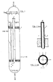
- FIG. 1 The apparatus according to the invention is also illustrated, as an example and in non-limitative form, by means of figure 1, according to which figure an aqueous area solution (1), having for instance the following features: falls, by means of a spray nozzle (2), onto the uppermost tube sheet (3) of a falling-film heat exchanger, heated by saturated steam (4) (at 25 kg/cm 2 , absolute), said steam being removed as condensate (5).
- the liquid forms a shallow heel and flows through the tangential distribution holes (6) in the side wall of the sleeves (7), projecting from of said sheet (see details in figures 1/bis and 1/ter), said sleeves being closed, at their uppermost end, by a blind disk (8).
- a liquid film is thus formed on the inner wall of the pipes (9), which film flows downwards in equicurrent to the gases (prevailingly NH 3 , CO 2 , H 2 0) released during the fall.
- the phases are sharply separated; the liquid forms a heel on the (tapered) stripper bottom and leaves the stripper through nozzle (10), while the vapours are recycled upwards by a central piping (11) surmounted by a chimney canopy (12) and definitively leave the stripper through nozzle (13).
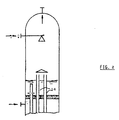
- the central piping (11), as already stated, can obviously be replaced by a suitable number of pipes (14) of the tube-bundle, having a cumulative cross section equivalent to the cross section of piping (11), said pipes (14) being supplied with longer sleeves and being open at the top and without holes for distributing the liquid (see figure 2), up to a height at least equal to the height of said sleeves.
Claims (3)
Applications Claiming Priority (2)
| Application Number | Priority Date | Filing Date | Title |
|---|---|---|---|
| IT2210383 | 1983-07-18 | ||
| IT22103/83A IT1163795B (it) | 1983-07-18 | 1983-07-18 | Apparecchio per lo strippaggio dell'ammoniaca dalle soluzioni provenienti dalla sintesi dell'urea |
Publications (2)
| Publication Number | Publication Date |
|---|---|
| EP0132193A1 EP0132193A1 (de) | 1985-01-23 |
| EP0132193B1 true EP0132193B1 (de) | 1987-12-16 |
Family
ID=11191538
Family Applications (1)
| Application Number | Title | Priority Date | Filing Date |
|---|---|---|---|
| EP84401453A Expired EP0132193B1 (de) | 1983-07-18 | 1984-07-10 | Fallfilm-Vorrichtung zur Gleichstromverdampfung einer Flüssigkeit |
Country Status (10)
| Country | Link |
|---|---|
| US (1) | US4747915A (de) |
| EP (1) | EP0132193B1 (de) |
| JP (1) | JPS6075302A (de) |
| BR (1) | BR8403534A (de) |
| CA (1) | CA1248866A (de) |
| DE (1) | DE3468085D1 (de) |
| ES (1) | ES534370A0 (de) |
| IN (1) | IN161938B (de) |
| IT (1) | IT1163795B (de) |
| PT (1) | PT78876A (de) |
Families Citing this family (16)
| Publication number | Priority date | Publication date | Assignee | Title |
|---|---|---|---|---|
| FI71067C (fi) * | 1983-12-05 | 1986-11-24 | Rosenlew Ab Oy W | Enligt principen fallande film fungerande avdunstningsenhet i orm av ett laongt roer och foerfarande foer industning av vetskor medelst naemnda avdunstningsenhet |
| NL8602769A (nl) * | 1986-11-03 | 1988-06-01 | Stamicarbon | Werkwijze voor het concentreren van een ureumoplossing en inrichting voor het uitvoeren van de werkwijze. |
| JPH0365675A (ja) * | 1989-08-04 | 1991-03-20 | Nippon Telegr & Teleph Corp <Ntt> | 光ファイバ磁界傾斜センサ |
| CH679485A5 (de) * | 1989-12-29 | 1992-02-28 | Ammonia Casale Sa | |
| US5069750A (en) * | 1990-04-12 | 1991-12-03 | Polysar Financial Services S.A. | Distributor for a devolatilizer |
| DE10217605A1 (de) * | 2002-04-19 | 2003-11-06 | Wme Ges Fuer Windkraftbetr Ene | Fallrohrverdampfer, sowie Einlaufvorrichtung hierfür |
| US7332058B2 (en) * | 2003-07-31 | 2008-02-19 | Fina Technology, Inc. | Heat exchanger and process for devolatilizing polymers using same |
| NO320779B1 (no) * | 2004-06-14 | 2006-01-30 | Inst Energiteknik | Innlopsinnretning |
| US7473278B2 (en) * | 2004-09-16 | 2009-01-06 | Smith & Nephew, Inc. | Method of surface oxidizing zirconium and zirconium alloys and resulting product |
| JP5495520B2 (ja) * | 2008-07-23 | 2014-05-21 | 三菱重工業株式会社 | 排ガス中の二酸化炭素回収装置 |
| US8361381B2 (en) * | 2008-09-25 | 2013-01-29 | Smith & Nephew, Inc. | Medical implants having a porous coated surface |
| CN102861449A (zh) * | 2012-10-15 | 2013-01-09 | 江苏中圣高科技产业有限公司 | 一种强化传热和防止结垢的蒸发器 |
| CN106693432B (zh) * | 2017-03-22 | 2023-12-12 | 中国石油大学(华东) | 一种离心旋流除沫型气液混相进料分布器 |
| CN109942043B (zh) * | 2019-04-26 | 2023-09-19 | 中创水务科技环保(广东)有限公司 | 一种渗滤液处理工艺及装置 |
| EP3733279A1 (de) * | 2019-05-03 | 2020-11-04 | Yara International ASA | Hochdruckstripper zur verwendung in harnstoffanlagen |
| CN112221169A (zh) * | 2019-07-15 | 2021-01-15 | 合众思(北京)环境工程有限公司 | 一种mvr蒸发结晶系统 |
Family Cites Families (28)
| Publication number | Priority date | Publication date | Assignee | Title |
|---|---|---|---|---|
| US28524A (en) * | 1860-05-29 | Latjme daniel wagnek | ||
| DE69707C (de) * | 1892-03-15 | 1893-07-11 | L. MAY in Ung.-Ostra, Mähren | Verdampf- oder Kühlapparat |
| DE232488C (de) * | 1910-02-28 | |||
| US1004087A (en) * | 1910-11-01 | 1911-09-26 | Franz Scheinemann | Evaporating apparatus. |
| US2224025A (en) * | 1936-09-10 | 1940-12-03 | American Lurgi Corp | Apparatus for the distillation of liquids having relatively high boiling points |
| BE451992A (de) * | 1941-05-19 | |||
| DE861991C (de) * | 1943-02-23 | 1953-01-08 | Bayer Ag | Vorrichtung zum Eindampfen von Fluessigkeiten |
| GB723344A (en) * | 1952-03-19 | 1955-02-09 | Monsanto Chemicals | Improvements in or relating to process for concentration of aqueous solutions of fusible caustic alkali |
| US2701262A (en) * | 1953-02-02 | 1955-02-01 | Chemical Construction Corp | Urea purification |
| US3147174A (en) * | 1959-10-14 | 1964-09-01 | Chemical Construction Corp | Low moisture urea melt |
| FR1248535A (fr) * | 1959-11-05 | 1960-12-16 | Appareil évaporatoire | |
| US3087533A (en) * | 1960-01-06 | 1963-04-30 | Whitlock Mfg Company | Drying apparatus and method |
| FR1393567A (fr) * | 1964-02-14 | 1965-03-26 | Procédé et dispositif de concentration-cristallisation en continu des solutions liquides telles que les sirops sucrés | |
| NL145541B (nl) * | 1964-02-17 | 1975-04-15 | Allied Chem | Werkwijze voor het ontleden van ammoniumcarbamaat. |
| NL141179B (nl) * | 1967-01-20 | 1974-02-15 | Whitlock Mfg Co | Werkwijze en inrichting voor de bereiding van ureum. |
| US3405689A (en) * | 1967-05-29 | 1968-10-15 | Stauffer Chemical Co | Apparatus for boiling liquids by falling film heating |
| NL6804152A (de) * | 1968-03-22 | 1969-09-24 | ||
| US3822192A (en) * | 1971-12-08 | 1974-07-02 | Aluminum Co Of America | Evaporative method |
| US4094734A (en) * | 1973-10-15 | 1978-06-13 | Henderson Industrial Corporation | Evaporator and treatment of viscous brines |
| IT1009381B (it) * | 1974-03-25 | 1976-12-10 | Sir Soc Italiana Resine Spa | Procedimento per la dissalazione dell acqua di mare e delle acque salmastre |
| DE2614587A1 (de) * | 1976-04-05 | 1977-10-13 | Metallgesellschaft Ag | Verfahren zum eindampfen wasserhaltiger fluessigkeiten |
| US4217176A (en) * | 1978-02-06 | 1980-08-12 | Aqua-Chem, Inc. | Evaporator |
| DE2812094A1 (de) * | 1978-03-20 | 1979-09-27 | Goeppner Kaiserslautern Eisen | Fallstromverdampfer |
| JPS5826909B2 (ja) * | 1979-09-14 | 1983-06-06 | 東洋エンジニアリング株式会社 | 尿素水溶液の濃縮方法 |
| FI60299C (fi) * | 1980-01-24 | 1983-06-28 | Rintekno Oy | Foerfarande foer foeraongning av vaetska och anordning foer geomfoerande av foerfarandet |
| JPS56128749A (en) * | 1980-03-13 | 1981-10-08 | Mitsui Toatsu Chem Inc | Stripping of unreacted material in urea preparation process |
| IT1148829B (it) * | 1980-05-16 | 1986-12-03 | Snam Progetti | Dispositivo per la distribuzione di liquido sotto forma di film in apparecchiature verticali di scambio termico |
| NL8102307A (nl) * | 1981-05-12 | 1982-12-01 | Esmil Bv | Inrichting en werkwijze voor het indikken door verdampen van een vloeistof. |
-
1983
- 1983-07-18 IT IT22103/83A patent/IT1163795B/it active
-
1984
- 1984-07-10 EP EP84401453A patent/EP0132193B1/de not_active Expired
- 1984-07-10 PT PT78876A patent/PT78876A/pt not_active IP Right Cessation
- 1984-07-10 IN IN493/CAL/84A patent/IN161938B/en unknown
- 1984-07-10 DE DE8484401453T patent/DE3468085D1/de not_active Expired
- 1984-07-11 CA CA000458668A patent/CA1248866A/en not_active Expired
- 1984-07-16 BR BR8403534A patent/BR8403534A/pt not_active IP Right Cessation
- 1984-07-17 ES ES534370A patent/ES534370A0/es active Granted
- 1984-07-18 JP JP59147724A patent/JPS6075302A/ja active Granted
-
1986
- 1986-03-06 US US06/837,656 patent/US4747915A/en not_active Expired - Lifetime
Also Published As
| Publication number | Publication date |
|---|---|
| DE3468085D1 (en) | 1988-01-28 |
| EP0132193A1 (de) | 1985-01-23 |
| IT8322103A1 (it) | 1985-01-18 |
| CA1248866A (en) | 1989-01-17 |
| IT8322103A0 (it) | 1983-07-18 |
| US4747915A (en) | 1988-05-31 |
| JPH0380521B2 (de) | 1991-12-25 |
| PT78876A (en) | 1984-08-01 |
| BR8403534A (pt) | 1985-06-25 |
| JPS6075302A (ja) | 1985-04-27 |
| ES8507006A1 (es) | 1985-09-01 |
| IN161938B (de) | 1988-02-27 |
| ES534370A0 (es) | 1985-09-01 |
| IT1163795B (it) | 1987-04-08 |
Similar Documents
| Publication | Publication Date | Title |
|---|---|---|
| EP0132193B1 (de) | Fallfilm-Vorrichtung zur Gleichstromverdampfung einer Flüssigkeit | |
| FI80218B (fi) | Foerfarande och anlaeggning foer rening av en tvaokomponentvaetskeblandning medelst destillering. | |
| US4169856A (en) | Process for the preparation and the recovery of ethanolamines | |
| JP2012502889A (ja) | 1つまたはそれより多くのアルカノールアミンを含有する混合物を連続的に蒸留分離するための装置および方法 | |
| EP0055607B1 (de) | Verfahren zur Rückgewinnung von olefinischen Nitrilen | |
| EP0752416B1 (de) | Verfahren und Apparat zur Gewinnung von kondensierbaren Stoffen aus dem Dampf von einem Vakuumverdampfer der Harnstoffsynthese | |
| EP0002298B1 (de) | Verfahren und Apparat zur Entfernung von Ammoniumkarbamat aus einer Harnstoffsynthese-Lösung | |
| US5384404A (en) | Process for manufacturing melamine from urea | |
| SU1494864A3 (ru) | Способ получени мочевины | |
| RU2275355C2 (ru) | Конденсатор карбамата и способ модернизации существующего конденсатора карбамата | |
| US5527943A (en) | Method for removing acid and saline contaminants from a gaseous stream leaving a dimethylcarbonate synthesis reactor | |
| US5190665A (en) | Process and apparatus for removing carbon dioxide and stripping another component from a liquid stream | |
| JPH03170452A (ja) | 水、二酸化炭素及びアミンを含有する混合物から水を分離する方法 | |
| EP0270953A1 (de) | Verfahren zur Herstellung von trockener Alkansulfonsäure | |
| KR0172652B1 (ko) | 디메틸 카르보네이트 합성공정에서 응축상의 반응유출물로부터 산과 염 불순물을 제거하는 방법 | |
| EA024085B1 (ru) | Способ и установка для производства мочевины | |
| EP3300784A1 (de) | Quenchingsverfahren zur herstellung ein ammoniumsulfatsstrom | |
| DK158657B (da) | Fremgangsmaade til udvinding af en dialkanolamin fra en blanding, der indeholder oxazolidon. | |
| US5019218A (en) | Vacuum distillation process | |
| CA1333912C (en) | Process for concentrating a urea solution and installation for carrying out the process | |
| US10058796B2 (en) | Evaporator and process for use thereof | |
| SU1725939A1 (ru) | Выпарной аппарат | |
| EP4082643A1 (de) | Verbesserungen an einer ausrüstung einer harnstoffanlage | |
| RU2316542C2 (ru) | Способ и установка для получения мочевины | |
| EA007593B1 (ru) | Способ получения водного раствора гидроксиламина |
Legal Events
| Date | Code | Title | Description |
|---|---|---|---|
| PUAI | Public reference made under article 153(3) epc to a published international application that has entered the european phase |
Free format text: ORIGINAL CODE: 0009012 |
|
| AK | Designated contracting states |
Designated state(s): BE DE FR GB IT NL |
|
| 17P | Request for examination filed |
Effective date: 19850515 |
|
| ITF | It: translation for a ep patent filed |
Owner name: ISTITUTO GUIDO DONEGANI S.P.A. |
|
| GRAA | (expected) grant |
Free format text: ORIGINAL CODE: 0009210 |
|
| AK | Designated contracting states |
Kind code of ref document: B1 Designated state(s): BE DE FR GB IT NL |
|
| REF | Corresponds to: |
Ref document number: 3468085 Country of ref document: DE Date of ref document: 19880128 |
|
| R20 | Corrections of a patent specification |
Effective date: 19880204 |
|
| ET | Fr: translation filed | ||
| PLBE | No opposition filed within time limit |
Free format text: ORIGINAL CODE: 0009261 |
|
| STAA | Information on the status of an ep patent application or granted ep patent |
Free format text: STATUS: NO OPPOSITION FILED WITHIN TIME LIMIT |
|
| 26N | No opposition filed | ||
| ITPR | It: changes in ownership of a european patent |
Owner name: ATTO DI IDENTIFICAZIONE;TECNOPART S.R.L. |
|
| ITPR | It: changes in ownership of a european patent |
Owner name: FUSIONI;MONTEDIPE S.R.L. |
|
| ITTA | It: last paid annual fee | ||
| ITPR | It: changes in ownership of a european patent |
Owner name: CAMBIO RAGIONE SOCIALE;ECP ENICHEM POLIMERI S.R.L. |
|
| ITPR | It: changes in ownership of a european patent |
Owner name: CESSIONE;ENICHEM AGRICOLTURA S.P.A. |
|
| ITPR | It: changes in ownership of a european patent |
Owner name: CESSIONE;SNAMPROGETTI S.P.A. |
|
| PGFP | Annual fee paid to national office [announced via postgrant information from national office to epo] |
Ref country code: GB Payment date: 19980701 Year of fee payment: 15 |
|
| PGFP | Annual fee paid to national office [announced via postgrant information from national office to epo] |
Ref country code: FR Payment date: 19980709 Year of fee payment: 15 |
|
| PGFP | Annual fee paid to national office [announced via postgrant information from national office to epo] |
Ref country code: DE Payment date: 19980720 Year of fee payment: 15 |
|
| PGFP | Annual fee paid to national office [announced via postgrant information from national office to epo] |
Ref country code: BE Payment date: 19980914 Year of fee payment: 15 |
|
| PG25 | Lapsed in a contracting state [announced via postgrant information from national office to epo] |
Ref country code: GB Free format text: LAPSE BECAUSE OF NON-PAYMENT OF DUE FEES Effective date: 19990710 |
|
| PG25 | Lapsed in a contracting state [announced via postgrant information from national office to epo] |
Ref country code: FR Free format text: THE PATENT HAS BEEN ANNULLED BY A DECISION OF A NATIONAL AUTHORITY Effective date: 19990731 Ref country code: BE Free format text: LAPSE BECAUSE OF NON-PAYMENT OF DUE FEES Effective date: 19990731 |
|
| BERE | Be: lapsed |
Owner name: MONTEDISON S.P.A. Effective date: 19990731 |
|
| GBPC | Gb: european patent ceased through non-payment of renewal fee |
Effective date: 19990710 |
|
| PG25 | Lapsed in a contracting state [announced via postgrant information from national office to epo] |
Ref country code: DE Free format text: LAPSE BECAUSE OF NON-PAYMENT OF DUE FEES Effective date: 20000503 |
|
| REG | Reference to a national code |
Ref country code: FR Ref legal event code: ST |
|
| PGFP | Annual fee paid to national office [announced via postgrant information from national office to epo] |
Ref country code: NL Payment date: 20010730 Year of fee payment: 18 |
|
| PG25 | Lapsed in a contracting state [announced via postgrant information from national office to epo] |
Ref country code: NL Free format text: LAPSE BECAUSE OF NON-PAYMENT OF DUE FEES Effective date: 20030201 |
|
| NLV4 | Nl: lapsed or anulled due to non-payment of the annual fee |
Effective date: 20030201 |