EP0128820A2 - Verfahren und Anlage zum Mustervergleich - Google Patents
Verfahren und Anlage zum Mustervergleich Download PDFInfo
- Publication number
- EP0128820A2 EP0128820A2 EP84401153A EP84401153A EP0128820A2 EP 0128820 A2 EP0128820 A2 EP 0128820A2 EP 84401153 A EP84401153 A EP 84401153A EP 84401153 A EP84401153 A EP 84401153A EP 0128820 A2 EP0128820 A2 EP 0128820A2
- Authority
- EP
- European Patent Office
- Prior art keywords
- pattern
- master
- circuit
- matching
- extracted
- Prior art date
- Legal status (The legal status is an assumption and is not a legal conclusion. Google has not performed a legal analysis and makes no representation as to the accuracy of the status listed.)
- Granted
Links
Images


Classifications
-
- H—ELECTRICITY
- H01—ELECTRIC ELEMENTS
- H01M—PROCESSES OR MEANS, e.g. BATTERIES, FOR THE DIRECT CONVERSION OF CHEMICAL ENERGY INTO ELECTRICAL ENERGY
- H01M4/00—Electrodes
- H01M4/02—Electrodes composed of, or comprising, active material
- H01M4/62—Selection of inactive substances as ingredients for active masses, e.g. binders, fillers
-
- G—PHYSICS
- G06—COMPUTING; CALCULATING OR COUNTING
- G06V—IMAGE OR VIDEO RECOGNITION OR UNDERSTANDING
- G06V10/00—Arrangements for image or video recognition or understanding
- G06V10/20—Image preprocessing
- G06V10/24—Aligning, centring, orientation detection or correction of the image
- G06V10/245—Aligning, centring, orientation detection or correction of the image by locating a pattern; Special marks for positioning
-
- G—PHYSICS
- G06—COMPUTING; CALCULATING OR COUNTING
- G06F—ELECTRIC DIGITAL DATA PROCESSING
- G06F18/00—Pattern recognition
- G06F18/20—Analysing
- G06F18/21—Design or setup of recognition systems or techniques; Extraction of features in feature space; Blind source separation
- G06F18/211—Selection of the most significant subset of features
-
- G—PHYSICS
- G06—COMPUTING; CALCULATING OR COUNTING
- G06F—ELECTRIC DIGITAL DATA PROCESSING
- G06F18/00—Pattern recognition
- G06F18/20—Analysing
- G06F18/28—Determining representative reference patterns, e.g. by averaging or distorting; Generating dictionaries
-
- G—PHYSICS
- G06—COMPUTING; CALCULATING OR COUNTING
- G06V—IMAGE OR VIDEO RECOGNITION OR UNDERSTANDING
- G06V10/00—Arrangements for image or video recognition or understanding
- G06V10/70—Arrangements for image or video recognition or understanding using pattern recognition or machine learning
- G06V10/74—Image or video pattern matching; Proximity measures in feature spaces
- G06V10/75—Organisation of the matching processes, e.g. simultaneous or sequential comparisons of image or video features; Coarse-fine approaches, e.g. multi-scale approaches; using context analysis; Selection of dictionaries
- G06V10/758—Involving statistics of pixels or of feature values, e.g. histogram matching
-
- G—PHYSICS
- G06—COMPUTING; CALCULATING OR COUNTING
- G06V—IMAGE OR VIDEO RECOGNITION OR UNDERSTANDING
- G06V10/00—Arrangements for image or video recognition or understanding
- G06V10/70—Arrangements for image or video recognition or understanding using pattern recognition or machine learning
- G06V10/77—Processing image or video features in feature spaces; using data integration or data reduction, e.g. principal component analysis [PCA] or independent component analysis [ICA] or self-organising maps [SOM]; Blind source separation
- G06V10/772—Determining representative reference patterns, e.g. averaging or distorting patterns; Generating dictionaries
-
- Y—GENERAL TAGGING OF NEW TECHNOLOGICAL DEVELOPMENTS; GENERAL TAGGING OF CROSS-SECTIONAL TECHNOLOGIES SPANNING OVER SEVERAL SECTIONS OF THE IPC; TECHNICAL SUBJECTS COVERED BY FORMER USPC CROSS-REFERENCE ART COLLECTIONS [XRACs] AND DIGESTS
- Y02—TECHNOLOGIES OR APPLICATIONS FOR MITIGATION OR ADAPTATION AGAINST CLIMATE CHANGE
- Y02E—REDUCTION OF GREENHOUSE GAS [GHG] EMISSIONS, RELATED TO ENERGY GENERATION, TRANSMISSION OR DISTRIBUTION
- Y02E60/00—Enabling technologies; Technologies with a potential or indirect contribution to GHG emissions mitigation
- Y02E60/10—Energy storage using batteries
Definitions
- the present invention relates to a pattern recognition apparatus, more particularly to a pattern matching method and apparatus wherein the optimum master pattern can be selected quantitatively when the pattern matching is processed.
- An object of the present invention is to provide a pattern matching method and apparatus based on a concept of picking up a master sample that includes a master pattern and automatically detecting a pattern having the most distinctive features, wherein operation by the operator is not necessary as the most appropriate master pattern is automatically obtained. That is, the master pattern in the image picture having the most distinctive features i.e., having the minimum matching degree to the other patterns, is selected and memorized, and a pattern recognition having a high recognition rate and highly accurate positioning through the pattern recognition is carried out using the master pattern.
- a pattern matching method comprising the steps of, sequentially extracting a pattern with a predetermined size from an image in order to form a master pattern, mutually collating each extracted pattern with all the other patterns in the image, registering the extracted pattern, which has the minimum similarity to the other patterns, as a master pattern, and identifying the object pattern by the pattern matching procedure between the image including the object pattern and the master pattern.
- a pattern matching apparatus having an image pickup system for picking up an image of a sample put on a sample feed mechanism; an analog to digital (A/D) converter circuit for converting an analog pickup signal from the image pickup system to a digital signal; an object pattern memory for receiving the output of the A/D converter circuit; a master pattern forming circuit connected to the object pattern memory; a master pattern memory connected to the master pattern forming circuit; and a pattern matching circuit connected to the object pattern memory and the master pattern memory; wherein the master pattern forming circuit. comprises a distinctive pattern detection circuit for detecting the most distinctive pattern portion in the object pattern memory and for storing the detected pattern portion into the master pattern memory.
- FIG. 1 shows a block circuit diagram of a pad pattern position recognition apparatus for a fully automatic wire bonder using the pattern matching method and apparatus according to a first embodiment of the present invention.
- a sample feed mechanism 1 introduces a master sample 2 or an object sample 3 to be recognized placed thereon, into an image pickup system, for example a television (TV) camera 4.
- the pickup signal by the TV camera 4 is converted to a digital signal through an analog to digital (A/D) conversion circuit 5 and stored in a frame memory 6, which is an object pattern memory.
- A/D analog to digital
- a pattern matching circuit 9 When the object sample 3 is placed on the sample feed mechanism 1 and a master pattern has been stored in a master pattern memory 7, in a pattern matching circuit 9, the collation (pattern matching) between the master pattern and the image of the object pattern in the frame memory 6 is processed and a pattern portion which is matched at the highest degree to the master pattern is sent to a control circuit 10 as a desired pad position.
- the control circuit 10 controls a bonding mechanism 11 using the positioning information and automatic wire bonding is then carried out.
- the most appropriate pattern portion is selected as a master pattern in a master pattern forming circuit 8 from a master sample image stored in the frame memory 6 and picked up from the master sample 2 placed on the sample feed mechanism 1, and the selected portion is stored into a master pattern memory 7.
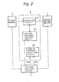
- Figure 2 is a block circuit diagram of the master pattern forming circuit 8 and circuits connected thereto.
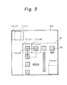
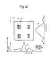
- Figure 3 shows an image 60 stored in the frame memory 6. The images showing pads 62 hatched on a chip 61 of an integrated circuit (IC) are included in the image 60.
- IC integrated circuit
- An extraction circuit 81 extracts a small area (0, 0) from the frame memory 6.
- a pattern in the small area is stored in the master pattern memory 7 as a temporary master pattern.
- a pattern matching control circuit 82 makes the pattern matching circuit 9 to perform the patterns matching between the master pattern and all the patterns stored in the frame memory 6.
- the pattern matching circuit 9 scans, in the frame memory 6, the pattern in the master pattern memory 7.
- the pattern matching degree signal S(92) between the master pattern and the corresponding pattern portions in the frame memory 6, and scanning position signal S(91) are sent to a similar pattern detection circuit 83.
- the similar pattern detection circuit 83 checks the sequentially transferred pattern matching degree signal S(92), and looks for the highest (first rank) pattern matching degree other than the extracting position (0, 0) of the extraction pattern.
- the first rank pattern matching degree is stored as a similar pattern matching degree M 2 (0, 0) to the extraction pattern (0, 0).
- the reference symbol (0, 0) shows coordinates at the upper left corner in the extraction pattern showi. in the Figure.
- the similar pattern detection circuit 83 includes a master pattern determination circuit.
- the extraction circuit 81 operates to store the next extraction pattern (1, 0) into the master pattern memory 7, looks for the first rank pattern matching degree, and obtains the similar pattern matching degree M 2 (1, 0).
- the above-mentioned extraction operation is performed to the end, namely the coordinates (x y n ) in the frame memory 6.
- Figure 4A shows a graph for the extraction pattern (0, 0).
- the abscissa of the graph is the scanning position signal S(91) transferred from the pattern matching circuit 9.
- the ordinate is the pattern matching degree signal S(92).
- Figs. 4A, 4B, and 4C patterns at the left side show extraction patterns. In the case of Fig.
- the similar pattern matching degree M 2 (0, 0) is 100 percent.
- Fig. 4B a similar graph is shown for the extraction pattern (x, , y 1 ) in Fig. 3. In the extraction area, one pad pattern is included. In this case, the pattern matching degree at the scanning position (x 1 , y 1 ) becomes, of course, 100 percent, also a pattern matching degree close to 100 percent is obtained at the position (x 2 , Y2 ).
- the pattern matching degree becomes 100 percent and this value is simultaneously the similar pattern matching degree M 2 (x 1 , y 1 ).
- Figure 4C shows a graph similar to Figs. 4A and 4B but corresponding to the extraction pattern (x 3 , y 3 ).
- the pattern matching degree at the scanning position (x 3 , y 3 ) becomes 100 percent, as in Fig. 4B.
- the pattern matching degree does not reach such a high degree except in the case of the scanning position (x 3 , y 3 ).
- the similar pattern matching degree M 2 (x 3 , y 3 ) is lower than that of the examples in Figs. 4A and 4B.
- the extraction pattern (x 3 , y 3 ) is a considerably distinctive pattern in the image 60.
- portions referred to as 6 are the extraction pattern themselves. These portions are, of course, not involved in the detection of the similar pattern matching degree M 2 .
- the extraction pattern having the minimum value M 2min out of all similar pattern matching degrees M 2 corresponding to all extraction patterns, is the most distinctive pattern in the image 60. If the master pattern determination circuit in the similar pattern detection circuit 83 determines the extraction pattern having the M 2min as a master pattern, the most reliable pattern matching process can be carried out.
- the similar pattern matching degrees M 2 to the extraction pattern which is determined to be most appropriate is checked by the operator. If M 2 ⁇ a, the extraction pattern is allowed to be the master pattern. If M 2 a, the extraction pattern is not allowed to be the master pattern. Therefore, the master pattern formed by the above process does not always provide the most appropriate master pattern, i.e., that which has the lowest similarity degree to the other extraction pattern, as does the present embodiment.
- the value a is an allowable similarity degree, for example, 80 percent.
- the forming of the master pattern, hitherto determined and indicated by the operator, is performed automatically and most appropriately and, as a result, a high performance pad pattern position recognition apparatus for a fully automatic wire bonder can be realized.
- FIG. 5 shows a block circuit diagram of the master pattern forming circuit 8 according to the second embodiment.
- the difference between the second embodiment and the circuit shown in Fig. 2 is the addition of an extraction size command circuit 84 and an extraction size determination circuit 85.
- the extraction size command circuit 84 commands an initial extraction size (area 65 in Fig. 6) of the given master sample image, to the extraction circuit 81.
- the extraction circuit 81 sequentially extracts the area having the size 65 from the master sample image.
- the similar pattern matching degree M 2min at size 65 is detected by the similar pattern detection circuit 83.
- the similar pattern matching degree M 2min is transferred to the extraction size determination circuit 85.
- the extraction size command circuit 84 performs processes similar to the above-mentioned processes. When these operations are repeated, the similar pattern matching degrees M 2min corresponding to each extraction size are obtained at the extraction size determination circuit 85, as shown in Fig. 7. After applying the plurality of extraction sizes, the extraction pattern having the minimum M 2min is determined as a master pattern. Using this method, the extraction size which has the least pattern matching degree to the other patterns in the master sample image, namely, the most distinctive pattern, can be determined.
- an allowable value "a" percent is predetermined as a master pattern regarding the similar pattern matching degrees M 2min , when the extraction size is changed sequentially and the value of M 2min becomes lower than "a" percent, the extraction size, at that moment, is determined as a master pattern size. As a result, the determination of the master pattern size can be speeded up.
- the master pattern size which was determined as a certain size, can be determined with an optimum value, automatically.
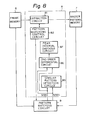
- Figure 8 shows a block circuit diagram of a master pattern forming circuit 8 according to a third embodiment of the present invention.
- the circuit 8 comprises the circuit in Fig. 2, a second order differential circuit 86, and a peak interval checking circuit 87.
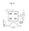
- the principle of the operation in the third embodiment is now explained with reference to Figs. 9 and 10.
- Curves 71 and 76 in Figs. 9 and 10 show pattern matching degrees between the object patterns 73 or 78 and moving master patterns 74 or 79, respectively, (corresponding to the portions referred to as 6 in the curves in Fig. 4A, 4B, and4C).
- the curves 71 and 76 where the object pattern and the master pattern include many longer figures in the lateral direction (Fig. 9)
- the curve showing the pattern matching degree has a gentle slope.
- the curve is steep.
- the sharper the curve the higher the positioning accuracy. Namely, when the curve is a gentle slope, as is the curve 71 in Fig. 9, the accuracy of the positioning decreases because the peaks at the matching position are not well-defined.
- Curves 72 and 77 in Figs. 9 and 10 show the pattern matching degree when the master pattern moves to the y direction.
- the curve 72 is sharp and the curve 77 is gentle.
- the positioning accuracy along the y direction is high, but the positioning accuracy along the x direction is low.
- the positioning accuracy along the x direction is high and the positioning accuracy along the y direction is low.
- both the patterns in Figs. 9 and 10 are not patterns appropriate for increasing the position accuracy.
- the pattern shown in F ig. 11, which has sharp curves in both the x and y directions, is the most appropriate pattern.
- the pattern matching apparatus comprises the second order differential circuit 86 and the peak interval checking circuit 87, shown in Fig. 8, as means to check whether the master pattern is appropriate or not.
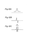
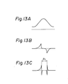
- the operations of the two circuits are explained with reference to Figs. 12A, 12B, and 12C, and Figs. 13A, 13B, and 13C.
- Curves shown in Figs. 12A and 13A are the curves showing the pattern matching degrees similar to those in Figs. 9 and 10.
- the second order differential circuit 86 forms second order differential curves, as shown in Figs. 12C and 13C, from the curves in Figs. 12A and 13A, respectively.
- 12B and 13B are first order differential curves, as a medium step therebetween.
- the second order differential curves each have two peaks.
- the length of peak intervals ta and lb corresponds to the sharpness of the original curves shown in Figs. 12A and 13A.
- the intervals ⁇ a and lb are checked by the peak interval checking circuit 87. If the intervals are shorter than a predetermined allowable length, the formed master pattern is determined as the most appropriate one. If the intervals are longer than the predetermined allowable length, instead of the initially selected master pattern, another master pattern, for example, having a pattern matching degree M 2 of the next lower rank, is accepted.
- a master pattern capable of a high accuracy positioning can be formed.
- Figure 14 shows the block circuit diagram of the extraction circuit 81, the extraction size command circuit 84, and the pattern matching control circuit 82.
- the X address counter 813 and the Y address counter 814 point out an address of the frame memory 6.
- An X size register 815 and a Y size register 816 indicate extraction sizes along the directions X and Y to the address counters, respectively.
- the extraction size command circuit 84 comprises an X size counter 841 and a Y size counter 842.
- the X size counter 841 and the Y size counter 842 supply information for designating the extraction size to the X size register and the Y size register, respectively.
- the pattern matching control circuit 82 comprises a flip-flop 821.
- the flip-flop 821 receives the signal from the Y size register 816, is set by the signal, supplies a start signal to the pattern matching circuit 9, and is reset by an end signal from the pattern matching circuit 9.
- Figure 15 shows a block circuit diagram of the similar pattern detection circuit 83 used in the apparatuses of the first, second, and third embodiments.
- a pattern matching degree signal S(92) from the pattern matching circuit 9 is supplied to a comparator 831 and, simultaneously, to a M ax register 832.
- the comparator 831 compares the value A of the signal S(92) with the value B of the M ax register. If A ⁇ B, a latch signal is sent to the M ax register 832 from the comparator 831, and the value A of the signal S(92) is stored in the Ma x register 832.
- the comparator 834 compares the value C of the M ax register 832 with the value D of a M in register 833.
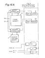
- Figures 16A and 16B show a block circuit diagram of the pattern matching circuit 9 usea in the apparatuses of the first, second, and third embodiments.
- the frame memory 6 is controlled by signals from a data buffer DB and from a decoder DC through a memory controller for the frame memory 6.
- the frame memory 6 supplies data of the object pattern to a shift register 931 in a correlator -1(93) and to a shift register 941 in a correlator -2(94) through a shift register 91, which converts the parallel signal to a series signal.
- Master pattern data from the master pattern memory 7 is also supplied to a shift register 933 in the correlator 93 and to a shift register 943 in the correlator 94 through a shift register 92, as for the data of the object pattern.
- An inverting exclusive logical summation between the outputs of the shift registers 931 and 941 and the outputs of the shift registers 933 and 943 occur one by one through exclusive NOR gates 932 and 942.
- the output of the exclusive NOR gate 932 is added to the output of the exclusive NOR gate 942 through an adder 951.
- the result is stored in a data memory 90.
- the data in the data memory 90 is controlled by a memory controller 901, is applied to an adder 952 through a data register 96, and is added to the summation of the next one line collation, namely, the output of the adder 951.
- the added value renews the stored value of the data memory 90.
- the pattern matching degree of one frame between the pattern in the frame memory 6 and the master pattern is obtained.
- the pattern matching degree is sent to the similar pattern detection circuit 83 as a form of the signal S(92).
- the scanning position signal S(91) is sent to the similar pattern detection circuit 83 from the memory controller 901.
Applications Claiming Priority (2)
| Application Number | Priority Date | Filing Date | Title |
|---|---|---|---|
| JP100962/83 | 1983-06-08 | ||
| JP58100962A JPS59226981A (ja) | 1983-06-08 | 1983-06-08 | パタ−ンマツチング方法および装置 |
Publications (4)
| Publication Number | Publication Date |
|---|---|
| EP0128820A2 true EP0128820A2 (de) | 1984-12-19 |
| EP0128820A3 EP0128820A3 (en) | 1988-07-27 |
| EP0128820B1 EP0128820B1 (de) | 1991-05-02 |
| EP0128820B2 EP0128820B2 (de) | 1996-05-29 |
Family
ID=14287975
Family Applications (1)
| Application Number | Title | Priority Date | Filing Date |
|---|---|---|---|
| EP84401153A Expired - Lifetime EP0128820B2 (de) | 1983-06-08 | 1984-06-06 | Verfahren und Anlage zum Mustervergleich |
Country Status (5)
| Country | Link |
|---|---|
| US (1) | US4805224A (de) |
| EP (1) | EP0128820B2 (de) |
| JP (1) | JPS59226981A (de) |
| KR (1) | KR890002287B1 (de) |
| DE (1) | DE3484522D1 (de) |
Cited By (3)
| Publication number | Priority date | Publication date | Assignee | Title |
|---|---|---|---|---|
| EP0251379A2 (de) * | 1986-06-24 | 1988-01-07 | POLYGRAM GmbH | Verfahren zum Ausrichten oder Positionieren von Gegenständen |
| EP1574991A1 (de) * | 2002-12-11 | 2005-09-14 | Seiko Epson Corporation | Extraktionseinrichtungfür ähnliche bilder, extraktionsverfahren für ähnliche bilder undextraktionsprogramm für ähnliche bilder |
| EP2244227A3 (de) * | 2009-04-22 | 2012-03-28 | AIT Austrian Institute of Technology GmbH | Verfahren zur Bestimmung von als Passpunkt einsetzbaren Bildausschnitten eines Masterbildes |
Families Citing this family (64)
| Publication number | Priority date | Publication date | Assignee | Title |
|---|---|---|---|---|
| JPS6346583A (ja) * | 1986-08-14 | 1988-02-27 | Toshiba Seiki Kk | パタ−ン認識方法 |
| JPS63211076A (ja) * | 1987-02-27 | 1988-09-01 | Hitachi Ltd | パタ−ン検査装置 |
| JPH0664614B2 (ja) * | 1987-02-27 | 1994-08-22 | 株式会社安川電機 | 階層化構造的テンプレ−ト・マツチング方法 |
| DE3720489A1 (de) * | 1987-06-20 | 1988-12-29 | Sood Ralf A | Verfahren zum lesen von text- und druckvorlagen |
| JP2539856B2 (ja) * | 1987-10-15 | 1996-10-02 | 株式会社ヒューテック | 印刷パタ―ン周期長のずれ検知方法 |
| JPH01140271A (ja) * | 1987-11-26 | 1989-06-01 | Oki Electric Ind Co Ltd | パターン欠陥検出装置 |
| US5127532A (en) * | 1988-06-24 | 1992-07-07 | Cimino William J | Automatic key identification system |
| US4899391A (en) * | 1988-06-24 | 1990-02-06 | Cimino William J | Automatic key identification system |
| US5406642A (en) * | 1988-12-23 | 1995-04-11 | Nec Corporation | Image matching method using direction sensitivity and vector smoothing functions for correcting matches |
| US5119436A (en) * | 1990-09-24 | 1992-06-02 | Kulicke And Soffa Industries, Inc | Method of centering bond positions |
| US5091968A (en) * | 1990-12-28 | 1992-02-25 | Ncr Corporation | Optical character recognition system and method |
| US10361802B1 (en) | 1999-02-01 | 2019-07-23 | Blanding Hovenweep, Llc | Adaptive pattern recognition based control system and method |
| US6418424B1 (en) | 1991-12-23 | 2002-07-09 | Steven M. Hoffberg | Ergonomic man-machine interface incorporating adaptive pattern recognition based control system |
| US6850252B1 (en) * | 1999-10-05 | 2005-02-01 | Steven M. Hoffberg | Intelligent electronic appliance system and method |
| US5903454A (en) | 1991-12-23 | 1999-05-11 | Hoffberg; Linda Irene | Human-factored interface corporating adaptive pattern recognition based controller apparatus |
| US6400996B1 (en) | 1999-02-01 | 2002-06-04 | Steven M. Hoffberg | Adaptive pattern recognition based control system and method |
| US7242988B1 (en) | 1991-12-23 | 2007-07-10 | Linda Irene Hoffberg | Adaptive pattern recognition based controller apparatus and method and human-factored interface therefore |
| US8352400B2 (en) | 1991-12-23 | 2013-01-08 | Hoffberg Steven M | Adaptive pattern recognition based controller apparatus and method and human-factored interface therefore |
| US5479533A (en) * | 1992-02-28 | 1995-12-26 | Yamatake-Honeywell Co., Ltd. | Pattern recognition apparatus and method using fuzzy logic |
| US5590048A (en) * | 1992-06-05 | 1996-12-31 | Fujitsu Limited | Block exposure pattern data extracting system and method for charged particle beam exposure |
| US5442572A (en) * | 1992-11-23 | 1995-08-15 | Ford Motor Company | Method and system for comparing free-form geometries using high density point data models |
| US5638301A (en) * | 1994-06-02 | 1997-06-10 | Ford Motor Company | Method and system for inspecting die sets using free-form inspection techniques |
| EP0804785A2 (de) * | 1994-12-06 | 1997-11-05 | Cirrus Logic, Inc. | Schaltungen, systeme und verfahren zur anzeigesteuerung von datenblöcken auf einem bildschirm |
| JPH07302344A (ja) * | 1995-01-17 | 1995-11-14 | Toshiba Seiki Kk | パターン認識装置 |
| US5659493A (en) * | 1995-03-03 | 1997-08-19 | Ford Motor Company | Virtual machining techniques for modifying computer models of parts |
| US5739518A (en) * | 1995-05-17 | 1998-04-14 | Metanetics Corporation | Autodiscrimination for dataform decoding and standardized recording |
| JPH09251536A (ja) * | 1996-03-15 | 1997-09-22 | Komatsu Ltd | パターンマッチングによる検査装置および検査方法 |
| US5911003A (en) * | 1996-04-26 | 1999-06-08 | Pressco Technology Inc. | Color pattern evaluation system for randomly oriented articles |
| US6222939B1 (en) * | 1996-06-25 | 2001-04-24 | Eyematic Interfaces, Inc. | Labeled bunch graphs for image analysis |
| KR100278064B1 (ko) * | 1997-08-20 | 2001-02-01 | 전주범 | 눈영역검출장치및방법 |
| US6301370B1 (en) | 1998-04-13 | 2001-10-09 | Eyematic Interfaces, Inc. | Face recognition from video images |
| US6272231B1 (en) | 1998-11-06 | 2001-08-07 | Eyematic Interfaces, Inc. | Wavelet-based facial motion capture for avatar animation |
| AU2004212509B2 (en) * | 1998-04-13 | 2005-09-08 | Google Llc | Face recognition from video images |
| AU3639699A (en) | 1998-04-13 | 1999-11-01 | Eyematic Interfaces, Inc. | Wavelet-based facial motion capture for avatar animation |
| US5969753A (en) * | 1998-04-24 | 1999-10-19 | Medar, Inc. | Method and system for detecting errors in a sample image |
| US6173213B1 (en) | 1998-05-11 | 2001-01-09 | Ellison Machinery Company | Motorized inbound laser orientation and wheel recognition station |
| DE69926699T2 (de) | 1998-08-31 | 2006-06-08 | International Business Machines Corp. | Unterscheidung zwischen Formularen |
| EP0984387B1 (de) * | 1998-08-31 | 2005-08-17 | International Business Machines Corporation | Unterscheidung zwischen Formularen |
| US7050655B2 (en) * | 1998-11-06 | 2006-05-23 | Nevengineering, Inc. | Method for generating an animated three-dimensional video head |
| US6714661B2 (en) | 1998-11-06 | 2004-03-30 | Nevengineering, Inc. | Method and system for customizing facial feature tracking using precise landmark finding on a neutral face image |
| US7050624B2 (en) * | 1998-12-04 | 2006-05-23 | Nevengineering, Inc. | System and method for feature location and tracking in multiple dimensions including depth |
| US7904187B2 (en) | 1999-02-01 | 2011-03-08 | Hoffberg Steven M | Internet appliance system and method |
| US6466695B1 (en) | 1999-08-04 | 2002-10-15 | Eyematic Interfaces, Inc. | Procedure for automatic analysis of images and image sequences based on two-dimensional shape primitives |
| AU7555900A (en) * | 1999-10-04 | 2001-05-10 | Hamamatsu Photonics K.K. | Camera system for high-speed image processing |
| US7787017B2 (en) * | 2000-05-18 | 2010-08-31 | OptigraP Sagl | Digital camera and method for identification of objects |
| US8682077B1 (en) | 2000-11-28 | 2014-03-25 | Hand Held Products, Inc. | Method for omnidirectional processing of 2D images including recognizable characters |
| US6917703B1 (en) | 2001-02-28 | 2005-07-12 | Nevengineering, Inc. | Method and apparatus for image analysis of a gabor-wavelet transformed image using a neural network |
| US7392287B2 (en) * | 2001-03-27 | 2008-06-24 | Hemisphere Ii Investment Lp | Method and apparatus for sharing information using a handheld device |
| DE10135817A1 (de) | 2001-07-23 | 2003-02-20 | Siemens Ag | Verfahren zum Ähnlichkeitsvergleich von zwei aus Polygonzügen aufgebauten, digitalen Bildern |
| US6853379B2 (en) * | 2001-08-13 | 2005-02-08 | Vidiator Enterprises Inc. | Method for mapping facial animation values to head mesh positions |
| US6876364B2 (en) | 2001-08-13 | 2005-04-05 | Vidiator Enterprises Inc. | Method for mapping facial animation values to head mesh positions |
| US6834115B2 (en) | 2001-08-13 | 2004-12-21 | Nevengineering, Inc. | Method for optimizing off-line facial feature tracking |
| JP3978098B2 (ja) * | 2002-08-12 | 2007-09-19 | 株式会社日立製作所 | 欠陥分類方法及びその装置 |
| US20050047647A1 (en) * | 2003-06-10 | 2005-03-03 | Ueli Rutishauser | System and method for attentional selection |
| US20050182692A1 (en) * | 2004-01-23 | 2005-08-18 | Woos Michael T. | Product finder system and method |
| US7416125B2 (en) * | 2005-03-24 | 2008-08-26 | Hand Held Products, Inc. | Synthesis decoding and methods of use thereof |
| CN101405104B (zh) | 2006-01-23 | 2011-05-25 | 海-科产品公司 | 钥匙复制机 |
| US9101990B2 (en) | 2006-01-23 | 2015-08-11 | Hy-Ko Products | Key duplication machine |
| JP4766008B2 (ja) * | 2007-06-29 | 2011-09-07 | 富士ゼロックス株式会社 | 真偽判定装置及び真偽判定プログラム |
| EP2424690A4 (de) | 2009-05-01 | 2013-11-27 | Hy Ko Products | Schlüsselrohlingsidentifikationssystem mit bartanalyse |
| MX343763B (es) | 2009-05-01 | 2016-11-18 | Hy-Ko Products | Sistema de identificación de llave en blanco con exploración digital de ranura. |
| US8326018B2 (en) * | 2010-05-29 | 2012-12-04 | Mentor Graphics Corporation | Fast pattern matching |
| US8994936B2 (en) * | 2012-11-22 | 2015-03-31 | Shenzhen China Star Optoelectronics Technology Co., Ltd | Pattern matching method, apparatus and line width measuring machine |
| WO2017024043A1 (en) | 2015-08-03 | 2017-02-09 | Hy-Ko Products Company | High security key scanning system |
Citations (1)
| Publication number | Priority date | Publication date | Assignee | Title |
|---|---|---|---|---|
| US3898617A (en) * | 1973-02-22 | 1975-08-05 | Hitachi Ltd | System for detecting position of pattern |
Family Cites Families (4)
| Publication number | Priority date | Publication date | Assignee | Title |
|---|---|---|---|---|
| US4200861A (en) * | 1978-09-01 | 1980-04-29 | View Engineering, Inc. | Pattern recognition apparatus and method |
| JPS5549779A (en) * | 1978-10-04 | 1980-04-10 | Hajime Sangyo Kk | Standard memory take-in method |
| JPS56132505A (en) * | 1980-03-24 | 1981-10-16 | Hitachi Ltd | Position detecting method |
| US4441205A (en) * | 1981-05-18 | 1984-04-03 | Kulicke & Soffa Industries, Inc. | Pattern recognition system |
-
1983
- 1983-06-08 JP JP58100962A patent/JPS59226981A/ja active Granted
-
1984
- 1984-06-06 EP EP84401153A patent/EP0128820B2/de not_active Expired - Lifetime
- 1984-06-06 DE DE8484401153T patent/DE3484522D1/de not_active Expired - Lifetime
- 1984-06-08 KR KR1019840003221A patent/KR890002287B1/ko not_active IP Right Cessation
-
1987
- 1987-02-27 US US07/020,201 patent/US4805224A/en not_active Expired - Lifetime
Patent Citations (1)
| Publication number | Priority date | Publication date | Assignee | Title |
|---|---|---|---|---|
| US3898617A (en) * | 1973-02-22 | 1975-08-05 | Hitachi Ltd | System for detecting position of pattern |
Non-Patent Citations (1)
| Title |
|---|
| PHILIPS TECHNICAL REVIEW, vol. 38, no. 11/12, 1978/1979, pages 356-363; E.H.J. PERSOON: "A system that can learn to recognize two-dimensional shapes" * |
Cited By (7)
| Publication number | Priority date | Publication date | Assignee | Title |
|---|---|---|---|---|
| EP0251379A2 (de) * | 1986-06-24 | 1988-01-07 | POLYGRAM GmbH | Verfahren zum Ausrichten oder Positionieren von Gegenständen |
| EP0251379B1 (de) * | 1986-06-24 | 1993-04-28 | POLYGRAM GmbH | Verfahren zum Ausrichten oder Positionieren von Gegenständen |
| EP1574991A1 (de) * | 2002-12-11 | 2005-09-14 | Seiko Epson Corporation | Extraktionseinrichtungfür ähnliche bilder, extraktionsverfahren für ähnliche bilder undextraktionsprogramm für ähnliche bilder |
| EP1574991A4 (de) * | 2002-12-11 | 2006-09-27 | Seiko Epson Corp | Extraktionseinrichtungfür ähnliche bilder, extraktionsverfahren für ähnliche bilder undextraktionsprogramm für ähnliche bilder |
| EP2244227A3 (de) * | 2009-04-22 | 2012-03-28 | AIT Austrian Institute of Technology GmbH | Verfahren zur Bestimmung von als Passpunkt einsetzbaren Bildausschnitten eines Masterbildes |
| AT509026A3 (de) * | 2009-04-22 | 2012-06-15 | Arc Austrian Res Centers Gmbh | Verfahren zur bestimmung von als passpunkt einsetzbaren bildausschnitten eines masterbildes |
| AT509026B1 (de) * | 2009-04-22 | 2013-04-15 | Arc Austrian Res Centers Gmbh | Verfahren zur bestimmung von als passpunkt einsetzbaren bildausschnitten eines masterbildes |
Also Published As
| Publication number | Publication date |
|---|---|
| JPH0215102B2 (de) | 1990-04-11 |
| EP0128820A3 (en) | 1988-07-27 |
| DE3484522D1 (de) | 1991-06-06 |
| EP0128820B1 (de) | 1991-05-02 |
| KR850000088A (ko) | 1985-02-25 |
| EP0128820B2 (de) | 1996-05-29 |
| US4805224A (en) | 1989-02-14 |
| JPS59226981A (ja) | 1984-12-20 |
| KR890002287B1 (ko) | 1989-06-27 |
Similar Documents
| Publication | Publication Date | Title |
|---|---|---|
| EP0128820A2 (de) | Verfahren und Anlage zum Mustervergleich | |
| EP0372762B1 (de) | Minutiae-Ermittlung für Fingerabdruck-Identifikation | |
| EP0854436B1 (de) | System und Verfahren zur Lageermittlung | |
| EP0669593A2 (de) | Erkennungsverfahren für eine zweidimensionale Kodierung | |
| JPH01196501A (ja) | ロボットの物体認識装置 | |
| JPH07220026A (ja) | 画像処理装置および方法 | |
| US5007097A (en) | Lead's position recognizing device | |
| EP0651337A1 (de) | Bilderkennungsverfahren, -geraet und bildverarbeitungsverfahren und -geraet | |
| JP3494388B2 (ja) | 指紋照合方法および指紋照合装置 | |
| JP2637591B2 (ja) | 位置認識装置及びその方法 | |
| JP2690103B2 (ja) | 指紋中心検出装置 | |
| JP3066137B2 (ja) | パターンマッチング方法 | |
| JP3082286B2 (ja) | 2値画化方法 | |
| JP2000194861A (ja) | 画像認識方法及び装置 | |
| JP3087788B2 (ja) | 部品の位置検出方法及び装置 | |
| JP3169046B2 (ja) | チップの認識方法及びその認識装置 | |
| JPH10332333A (ja) | 対象物の回転角と位置の検出方法 | |
| JPS58129888A (ja) | 円形端面の位置検出装置 | |
| JP3041056B2 (ja) | 半導体ペレットの検出方法 | |
| JPH05113315A (ja) | 円形画像データの中心位置検出方法 | |
| JP3063925B2 (ja) | 画像パターンマッチング装置 | |
| JPH0689343A (ja) | テンプレートマッチングの不感帯領域設定方法 | |
| JPH09147121A (ja) | ロボットの物体認識方法及びその装置 | |
| JP3441648B2 (ja) | ワーク姿勢識別装置 | |
| JPH05314261A (ja) | 画像認識方法 |
Legal Events
| Date | Code | Title | Description |
|---|---|---|---|
| PUAI | Public reference made under article 153(3) epc to a published international application that has entered the european phase |
Free format text: ORIGINAL CODE: 0009012 |
|
| AK | Designated contracting states |
Designated state(s): DE FR GB |
|
| PUAL | Search report despatched |
Free format text: ORIGINAL CODE: 0009013 |
|
| AK | Designated contracting states |
Kind code of ref document: A3 Designated state(s): DE FR GB |
|
| 17P | Request for examination filed |
Effective date: 19880926 |
|
| 17Q | First examination report despatched |
Effective date: 19891206 |
|
| GRAA | (expected) grant |
Free format text: ORIGINAL CODE: 0009210 |
|
| AK | Designated contracting states |
Kind code of ref document: B1 Designated state(s): DE FR GB |
|
| REF | Corresponds to: |
Ref document number: 3484522 Country of ref document: DE Date of ref document: 19910606 |
|
| ET | Fr: translation filed | ||
| PLBI | Opposition filed |
Free format text: ORIGINAL CODE: 0009260 |
|
| 26 | Opposition filed |
Opponent name: GAO GESELLSCHAFT FUER AUTOMATION UND ORGANISATION Effective date: 19920201 |
|
| PLAB | Opposition data, opponent's data or that of the opponent's representative modified |
Free format text: ORIGINAL CODE: 0009299OPPO |
|
| R26 | Opposition filed (corrected) |
Opponent name: GAO GESELLSCHAFT FUER AUTOMATION UND ORGANISATION Effective date: 19920201 |
|
| PUAH | Patent maintained in amended form |
Free format text: ORIGINAL CODE: 0009272 |
|
| STAA | Information on the status of an ep patent application or granted ep patent |
Free format text: STATUS: PATENT MAINTAINED AS AMENDED |
|
| 27A | Patent maintained in amended form |
Effective date: 19960529 |
|
| AK | Designated contracting states |
Kind code of ref document: B2 Designated state(s): DE FR GB |
|
| ET3 | Fr: translation filed ** decision concerning opposition | ||
| REG | Reference to a national code |
Ref country code: GB Ref legal event code: IF02 |
|
| PGFP | Annual fee paid to national office [announced via postgrant information from national office to epo] |
Ref country code: GB Payment date: 20030604 Year of fee payment: 20 |
|
| PGFP | Annual fee paid to national office [announced via postgrant information from national office to epo] |
Ref country code: FR Payment date: 20030610 Year of fee payment: 20 |
|
| PGFP | Annual fee paid to national office [announced via postgrant information from national office to epo] |
Ref country code: DE Payment date: 20030618 Year of fee payment: 20 |
|
| PG25 | Lapsed in a contracting state [announced via postgrant information from national office to epo] |
Ref country code: GB Free format text: LAPSE BECAUSE OF EXPIRATION OF PROTECTION Effective date: 20040605 |
|
| REG | Reference to a national code |
Ref country code: GB Ref legal event code: PE20 |