EP0125517B1 - Verstärkungscord mit Umschlingungsdraht - Google Patents
Verstärkungscord mit Umschlingungsdraht Download PDFInfo
- Publication number
- EP0125517B1 EP0125517B1 EP84104319A EP84104319A EP0125517B1 EP 0125517 B1 EP0125517 B1 EP 0125517B1 EP 84104319 A EP84104319 A EP 84104319A EP 84104319 A EP84104319 A EP 84104319A EP 0125517 B1 EP0125517 B1 EP 0125517B1
- Authority
- EP
- European Patent Office
- Prior art keywords
- steel wires
- hardness
- wrapping wire
- wire
- reinforcing
- Prior art date
- Legal status (The legal status is an assumption and is not a legal conclusion. Google has not performed a legal analysis and makes no representation as to the accuracy of the status listed.)
- Expired
Links
Images


Classifications
-
- D—TEXTILES; PAPER
- D07—ROPES; CABLES OTHER THAN ELECTRIC
- D07B—ROPES OR CABLES IN GENERAL
- D07B1/00—Constructional features of ropes or cables
- D07B1/06—Ropes or cables built-up from metal wires, e.g. of section wires around a hemp core
- D07B1/0606—Reinforcing cords for rubber or plastic articles
- D07B1/0613—Reinforcing cords for rubber or plastic articles the reinforcing cords being characterised by the rope configuration
-
- D—TEXTILES; PAPER
- D07—ROPES; CABLES OTHER THAN ELECTRIC
- D07B—ROPES OR CABLES IN GENERAL
- D07B2201/00—Ropes or cables
- D07B2201/10—Rope or cable structures
- D07B2201/1012—Rope or cable structures characterised by their internal structure
- D07B2201/102—Rope or cable structures characterised by their internal structure including a core
-
- D—TEXTILES; PAPER
- D07—ROPES; CABLES OTHER THAN ELECTRIC
- D07B—ROPES OR CABLES IN GENERAL
- D07B2201/00—Ropes or cables
- D07B2201/20—Rope or cable components
- D07B2201/2095—Auxiliary components, e.g. electric conductors or light guides
- D07B2201/2097—Binding wires
- D07B2201/2098—Binding wires characterized by special properties or the arrangements of the binding wire
-
- D—TEXTILES; PAPER
- D07—ROPES; CABLES OTHER THAN ELECTRIC
- D07B—ROPES OR CABLES IN GENERAL
- D07B2501/00—Application field
- D07B2501/20—Application field related to ropes or cables
- D07B2501/2046—Tyre cords
-
- Y—GENERAL TAGGING OF NEW TECHNOLOGICAL DEVELOPMENTS; GENERAL TAGGING OF CROSS-SECTIONAL TECHNOLOGIES SPANNING OVER SEVERAL SECTIONS OF THE IPC; TECHNICAL SUBJECTS COVERED BY FORMER USPC CROSS-REFERENCE ART COLLECTIONS [XRACs] AND DIGESTS
- Y10—TECHNICAL SUBJECTS COVERED BY FORMER USPC
- Y10S—TECHNICAL SUBJECTS COVERED BY FORMER USPC CROSS-REFERENCE ART COLLECTIONS [XRACs] AND DIGESTS
- Y10S57/00—Textiles: spinning, twisting, and twining
- Y10S57/902—Reinforcing or tyre cords
Definitions
- the invention relates to a reinforcing cord made of a plurality of steel wires for reinforcing elastomeric products, consisting of steel wires and at least one flat metal wrapping wire, the hardness of which is significantly lower than the hardness of the steel wires, one of the broad sides of the wrapping wire touching the steel wires.
- Such reinforcing cords are known from FR-A-731 314, which serve as bead reinforcement in car tires. It is particularly important here that in the reinforcing cords, even if they are embedded in the bead, the steel wires reinforcing the bead remain in a parallel arrangement. This can be ensured, for example, by wrapping very flat strips of a significantly softer material around the steel wires in such a way that part of the material of the flat strips is pressed into the cavities formed by the steel wires, as a result of which the steel wires are held in their position.
- the known reinforcement cords have not yet been used for the tread of tires.
- Fretting corrosion is always present when two metal surfaces come into contact with one another, these two metal surfaces being subjected to a slight mutual displacement under load. Such a condition occurs between the metal wires of the reinforcing cord, which take up the load in the elastomeric product, and the looping wires when the reinforced elastomeric product is dynamically stressed.
- the object of the present invention is to provide a reinforcing cord of the type mentioned at the outset, in which the risk of fretting corrosion in the supporting steel wires is largely reduced, while at the same time maintaining the other good properties of the reinforcing cord.
- the service life of the reinforced elastomeric material is to be increased.
- each loop wire is flattened, that the hardness of each loop wire is approximately 30 to 60% of the hardness of the steel wires, and the ratio of thickness to width of each loop wire between 0.4 and 0. 7 lies.
- each loop wire is preferably approximately 30 to 50% of the hardness of the steel wires and / or the ratio of thickness and width of each loop wire is between 0.5 to 0.6.
- the hardness of the steel wires used for pneumatic tires for reinforcing cords is between 795 and 917 HV 0.05.
- the Vickers hardness is given here. It is determined according to DIN 50133 sheet 2.
- Such steel wires have tensile strengths that are between 2,600 to 3,000 N / mm 2 .
- Steel wires with a higher tensile strength, for example 3,400 N / mm 2 have recently also been used. These steel wires then have a correspondingly higher hardness.
- the loop wire according to the invention should have a hardness of 275 to 509 HV 0.05, preferably up to 459 HV Have 0.05.
- Such a loop wire then has a tensile strength which is between 900 and 1,800 N / mm 2 , preferably up to 1,500 N / m M2.
- the hardness and the tensile strength can be adjusted in a known manner by selecting the type of steel (amount of carbon content, amount of alloy additives), reducing the pre-deformation or using a suitable heat treatment.
- Another metallic material with corresponding hardness properties or tensile strengths can also be used for the wrapping wires.
- a flat loop wire can also be used as the loop wire, by means of which, in addition to an increase in the resistance to the splice effect, a reduction in the overall diameter is achieved.
- the flat design of the loop wire reduces the risk of fretting corrosion with reinforcement cords if certain geometrical size ratios are maintained for the cross section of the loop wire, because in contrast to the loop wire with a circular cross section when using the loop wire with a flat cross-section no longer point-like, but linear contact between the loop wire and the supporting steel wires is achieved.
- dynamic loading corresponding to the stress conditions in the tire, the forces acting from outside are distributed over a larger area, which reduces the specific surface loading both for the load-bearing steel wires and for the wrapping wires.
- the twisted flat wire always has higher elongation values than a comparable round wire. This leads to better ductile behavior and thus to greater stress resistance.
- This flattened loop wire can be applied either by twisting the loop wire around the rope or by laying the loop wire with the broad side on the rope rotating about its own axis.
- the wrap wire can be flattened by rolling a wire with a round cross-section flat or by pulling a drawing die with a rectangular cross-section in the drawing hole can.
- d means the diameter of the steel wires, which is between 0.15 and 0.25 mm for conventional reinforcing cords.
- U is the wrap wire or the wrap wires, which in the embodiment have the usual round cross section and have a diameter of 0.12 or 0.15 mm and are flattened.
- this invention is not limited to the specified diameters of the steel wires or the wrapping wires.
- the cross-sectional area of the flattened loop wire is approximately the same size as the cross-sectional area of the wire with a round cross-section used for flattening, and is preferably approximately 0.01 to 0.02 mm 2 .
- the lay length of the round as well as the flat loop wires is advantageously 2.5 to 5 mm.
- the reinforcing cords equipped with such wrapping wires are advantageously used in the carcass in pneumatic vehicle tires.
- the metal wires also consist of a carbon alloy steel wire for reinforcing cords according to the invention.
- the steel wires must bond well with the elastomeric material.
- the steel wires are coated with a second material, plastic or another material, a good binding property having to be present between the steel wire and the coating material on the one hand and the coating material and elastomeric material on the other hand.
- Steel wires coated with brass are preferred.
- the compression modulus is determined in the following way: A reinforcing cord or rope is embedded in an elastomeric material with defined properties. During the embedding, the elastomeric material is formed into a cylindrical sample, the cross section of which is circular, and in whose axis the reinforcement cord or the reinforcement cable is arranged and embedded. The sample has a defined length and a defined diameter. The maximum possible load is determined by the pressure load on the two (circular) end faces. As a rule, the maximum possible load is reached when the sample bends sideways.
- the reinforcing cords according to the invention are preferably used in the manufacture of pneumatic vehicle tires, in particular pneumatic tires for trucks or earthmoving machines.
Landscapes
- Ropes Or Cables (AREA)
- Tires In General (AREA)
- Yarns And Mechanical Finishing Of Yarns Or Ropes (AREA)
- Tyre Moulding (AREA)
Description
- Die Erfindung betrifft einen Verstärkungscord aus mehreren Stahldrähten zur Verstärkung von elastomeren Erzeugnissen, bestehend aus Stahldrähten und mindestens einem flachen Umschlingungsdraht aus Metall, dessen Härte deutlich geringer ist als die Härte der Stahldrähte, wobei eine der Breitseiten des Umschlingungsdrahtes die Stahldrähte berührt.
- Derartige Verstärkungscorde sind aus FR-A-731 314 bekannt, welche als Wulstverstärkung im Autoreifen dienen. Hierbei kommt es besonders darauf an, dass in den Verstärkungscorden auch dann, wenn sie in den Wulst eingebettet sind, die den Wulst verstärkenden Stahldrähte in paralleler Anordnung bleiben. Dies kann zum Beispiel dadurch gewährleistet werden, dass sehr flache Bänder aus einem deutlich weicheren Werkstoff um die Stahldrähte derart gewickelt werden, dass ein Teil des Werkstoffes der flachen Bänder in die von den Stahldrähten gebildeten Hohlräume gepresstwird, wodurch die Stahldrähte in ihrer Lage festgehalten werden.
- Die bekannten Verstärkungscorde sind bisher für die Lauffläche von Reifen nicht eingesetzt worden.
- Es sind lediglich aus der DE-C-803 801 Verstärkungscorde mit flachem Umschlingungsdraht bekannt geworden. Der Umschlingungsdraht erfüllt dabei die Aufgabe, den Cordverbund zusammenzuhalten und ein Spleissen der Stahldrähte zu verhindern. Wenn ein solcher Cord in ein elastomeres Material eingebettet ist, so ist bei Belastung dieses Materials, beispielsweise eines Fahrzeugluftreifens, die Gefahr der Reibkorrosion gegeben. Die Reibkorrosion ist eine der Ursachen, die zur Reduzierung der Lebensdauer von mit Verstärkungscorden verstärkten elastomeren Erzeugnissen führen.
- Die Gefahr der Reibkorrosion ist immer dann gegeben, wenn zwei Metalloberflächen berührenden Kontakt haben, wobei diese beiden Metalloberflächen unter Belastung einer geringfügigen gegenseitigen Verschiebung unterworfen sind. Ein solcher Zustand tritt zwischen den Metalldrähten des Verstärkungscordes, welche im elastomeren Erzeugnis die Belastung aufnehmen, und den Umschlingungsdrähten bei dynamischer Beanspruchung des verstärkten elastomeren Erzeugnisses ein.
- Aufgabe der vorliegenden Erfindung ist es, einen Verstärkungscord der eingangs genannten Art zur Verfügung zu stellen, bei welchem die Gefahr der Reibkorrosion bei den tragenden Stahldrähten weitgehend reduziert wird, wobei gleichzeitig die anderen guten Eigenschaften des Verstärkungscordes erhalten bleiben. Die Lebensdauer des verstärkten elastomeren Materials soll erhöht werden.
- Diese Aufgabe wird bei Verstärkungscorden der eingangs genannten Art dadurch gelöst, dass jeder Umschtingungsdraht abgeflacht ist, dass die Härte jedes Umschlingungsdrahtes etwa 30 bis 60% der Härte der Stahldrähte beträgt, und das Verhältnis von Dicke zu Breite jedes Umschlingungsdrarites zwischen 0,4 und 0,7 liegt.
- Bevorzugt beträgt die Härte jedes Umschlingungsdrahtes etwa 30 bis 50% von der Härte der Stahldrähte und/oder liegt das Verhältnis von Dikke und Breite jedes Umschlingungsdrahtes zwischen 0,5 bis 0,6.
- Die Härte der bei Fahrzeugluftreifen für Verstärkungscorde verwendeten Stahldrähte liegen bei Werten von 795 bis 917 HV 0,05. Hierbei ist die Härte nach Vickers angegeben. Sie wird nach DIN 50133 Blatt 2 bestimmt. Solche Stahldrähte haben Zugfestigkeiten, die zwischen 2 600 bis 3 000 N/ mm2 liegen. Neuerdings werden auch Stahldrähte eingesetzt, die eine höhere Zugfestigkeit, beispielsweise 3 400 N/mm2, besitzen. Diese Stahldrähte besitzen dann eine entsprechend höhere Härte.
- Werden beispielsweise Stahldrähte mit einer Härte von etwa 917 HV 0,05 und einer Zugfestigkeit von etwa 3 000 N/mm2 zur Herstellung eines Verstärkungscordes eingesetzt, so soll der Umschlingungsdraht erfindungsgemäss eine Härte von 275 bis 509 HV 0,05, vorzugsweise bis 459 HV 0,05 aufweisen. Ein solcher Umschlingungsdraht hat dann eine Zugfestigkeit, die zwischen 900 und 1 800 N/mm2, vorzugsweise bis 1 500 N/m M2 liegt.
- Verwendet man erfindungsgemäss für den Umschlingungsdraht auch einen Stahldraht, so kann die Härte und die Zugfestigkeit in bekannter Weise über die Auswahl der Stahlsorte (Höhe des Kohlenstoffgehaltes, Höhe der Legierungszusätze), über eine Reduzierung der Vorverformung oder über eine geeignete Wärmenachbehandlung eingestellt werden. Für die Umschlingungsdrähte kann aber auch ein anderer metallischer Werkstoff mit entsprechenden Härteeigenschaften bzw. Zugfestigkeiten verwendet werden.
- Bei dem in der obengenannten DE-PS 803 801 beschriebenen Verstärkungscord kann als Umschlingungsdraht auch ein flacher Umschlingungsdraht eingesetzt werden, durch welchen neben einer Erhöhung der Widerstandskraft gegenüber der Spleisswirkung eine Verringerung des Gesamtdurchmessers erreicht wird.
- Nicht nur die geringere Härte des Umschlingungsdrahtes in den angegebenen Grenzen, sondern auch die flache Ausbildung des Umschlingungsdrahtes verringert die Gefahr der Reibkorrosion bei Verstärkungscorden, wenn beim Querschnitt des Umschlingungsdrahtes bestimmte geometrische Grössenverhältnisse eingehalten werden, weil im Gegensatz zum Umschlingungsdraht mit kreisförmigem Querschnitt beim Einsatz des Umschlingungsdrahtes mit flachem Querschnitt nicht mehr punktförmiger, sondern linienförmiger Kontakt zwischen Umschlingungsdraht und tragenden Stahldrähten erreicht wird. Bei dynamischer Belastung, entsprechend den Beanspruchungsverhältnissen im Reifen, verteilen sich die von aussen einwirkenden Kräfte somit auf eine grössere Fläche, wodurch die spezifische Flächenbelastung sowohl für die tragenden Stahldrähte als auch für die Umwicklungsdrähte verringert wird. Begünstigend wirkt sich dabei aus, dass der gedrehte Flachdraht je nach Schlaglänge in jedem Fall höhere Dehnwerte aufweist als ein vergleichbarer runder Draht. Dies führt zu einem besseren duktilen Verhalten und somit zu einer höheren Beanspruchbarkeit.
- Das Aufbringen dieses abgeflachten Umschlingungsdrahtes kann dadurch geschehen, dass entweder der Umschlingungsdraht um das Seil gezwirnt wird oder der Umschlingungsdraht auf das um seine eigene Achse rotierende Seil mit der Breitseite abgelegt wird.
- Die Abflachung des Umschlingungsdrahtes kann dadurch bewerkstelligt werden, dass ein Draht mit rundem Querschnitt flachgewalzt oder durch einen Ziehstein dessen Ziehloch rechteckigen Querschnitt aufweist, gezogen wird, wobei in Breitenrichtung quer zur Laufrichtung des Drahtes auf einen Formzwang verzichtet wird und dieses Drahtmaterial in dieser Richtung frei fliessen kann.
- Die Verringerung der Gefahr der Reibkorrosion auf erfindungsgemässe Weise lässt sich praktisch bei allen Verstärkungscord-Konstruktionen anwenden, welche Umschlingungsdrähte aufweisen.
- Um die Vielfalt der möglichen erfindungsgemässen Verstärkungscord-Konstruktionen aufzuzeigen, werden nachfolgend beispielsweise folgende Konstruktionen genannt:

- Hierin bedeutet d der Durchmesser der Stahldrähte, welcher bei üblichen Verstärkungscorden zwischen 0,15 und 0,25 mm liegt.
- Mit U ist der Umschlingungsdraht bzw. die Umschlingungsdrähte bezeichnet, welche in der Ausführungsform mit üblichen rundem Querschnitt einen Durchmesser von 0,12 bzw. 0,15 mm aufweisen und abgeflacht sind.
- Diese Erfindung beschränkt sich jedoch nicht auf die angegebenen Durchmesser der Stahldrähte bzw. der Umschlingungsdrähte.
- Die Querschnittsfläche des abgeflachten Umschlingungsdrahtes ist etwa gleich gross wie die Querschnittsfläche des zur Abflachung verwendeten Drahtes mit rundem Querschnitt und beträgt vorzugsweise etwa 0,01 bis 0,02 mm2.
- Die Schlaglänge der runden wie der flachen Umschlingungsdrähte liegt vorteilhafterweise bei 2,5 bis 5 mm. Die mit derartigen Umschlingungsdrähten ausgestatteten Verstärkungscorde werden bei Fahrzeugluftreifen vorteilhafterweise in der Karkasse eingesetzt.
- In der Regel bestehen die Metalldrähte auch für erfindungsgemässe Verstärkungscorde aus einem kohlenstofflegierten Stahldraht. Die Stahldrähte müssen eine gute Bindung mit dem elastomeren Material eingehen. Deshalb werden die Stahldrähte mit einem zweiten Material, Kunststoff oder einem anderen Material beschichtet, wobei zwischen Stahldraht und Beschichtungswerkstoff einerseits und Beschichtungswerkstoff und elastomeren Material andererseits eine gute Bindungseigenschaft vorhanden sein muss. Mit Messing beschichtete Stahldrähte finden bevorzugt Anwendung.
- Bei allen oben beschriebenen erfindungsgemässen Ausgestaltungen der Verstärkungscorde wurde festgestellt, dass die übrigen Eigenschaften der Verstärkungscorde beispielsweise Zugfestigkeit, Durchdringung des elastomeren Materials oder Kompressionsmodul höchstens in unwesentlicher Weise beeinflusst wurden.
- Der Kompressionsmodul wird auf folgende Weise bestimmt: Ein Verstärkungscord bzw. Verstärkungsseil wird in ein elastomeres Material mit definierten Eigenschaften eingebettet. Das elastomere Material wird bei der Einbettung zu einer zylinderförmigen Probe geformt, deren Querschnitt kreisförmig ist, und in deren Achse der Verstärkungscord bzw. das Verstärkungsseil angeordnet und eingebettet ist. Die Probe hat definierte Länge und definierten Durchmesser. Durch Druckbelastung der beiden (kreisförmigen) Stirnflächen wird die maximal mögliche Belastung ermittelt. In der Regel wird die maximal mögliche Belastung dann erreicht, wenn die Probe seitlich ausknickt.
- Die erfindungsgemässen Verstärkungscorde finden bevorzugt Verwendung bei der Herstellung von Fahrzeugluftreifen, insbesondere von Luftreifen für Lastkraftwagen oder Erdbewegungsmaschinen.
- Die Erfindung wird anhand der nachfolgenden Figuren näher erläutert. Es zeigen:
- Fig. 1 eine erfindungsgemässe Verstärkungscord-Konstruktion in vier Querschnitten,
- Fig. 2 den erfindungsgemässen Verstärkungscord nach Fig. 1 in Draufsicht,
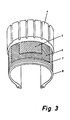
- Fig. 3 den schematischen Aufbau eines Reifens.
- Fig. 1 zeigt eine erfindungsgemässe Cordkonstruktion im Querschnitt, die aus sieben Litzen 2 mit jeweils vier einzelnen Stahldrähten 1 besteht, welche von einem Umschlingungsdraht 3, der abgeflacht ist, wendelförmig umwickelt ist, wobei eine der Breitseiten des Umschlingungsdrahtes 3 die Stahldrähte berührt. Hierbei sind vier Querschnitte senkrecht zur Seilachse nach den charakteristischen Verdrehungswinkeln 0°, 90°, 180° und 270° dargestellt, wobei die Zwirnrichtung des Umschlingungsdrahtes mit der des Pfeiles übereinstimmt.
- Fig. 2 zeigt den Verstärkungscord nach Fig. 1 in Draufsicht, wobei hier wiederum die charakteristischen Verdrehungswinkel 0°, 90°, 180° und 270° markiert sind. Gleichzeitig ist die Schlaglänge des Umschlingungsdrahtes mit S bezeichnet.
- Fig. 3 zeigt schematisch den Aufbau eines Reifens, in welchem erfindungsgemäss Verstärkungsteile eingebettet sind. Mit 4 ist die Lauffläche des Reifens bezeichnet, welcher hier als Radialreifen abgebildet ist. In die Lauffläche 4 sind zwei Lagen 5 und 6 von Verstärkungscorden eingebettet, welche unter einem bestimmten Winkel zur Umfangsrichtung verlaufen. Dieser Winkel richtet sich nach dem Einsatzgebiet des Reifens. In eine Karkasse 8 sind erfindungsgemässe Verstärkungscorde 7 in Umfangsrichtung des Reifenquerschnitts eingebettet. Die erfindungsgemässen Verstärkungscorde lassen sich auch in den Gürtellagen 5 und 6 einsetzen.
Claims (6)
Priority Applications (1)
| Application Number | Priority Date | Filing Date | Title |
|---|---|---|---|
| AT84104319T ATE32923T1 (de) | 1983-05-16 | 1984-04-17 | Verstaerkungscord mit umschlingungsdraht. |
Applications Claiming Priority (2)
| Application Number | Priority Date | Filing Date | Title |
|---|---|---|---|
| DE3317744 | 1983-05-16 | ||
| DE3317744A DE3317744C2 (de) | 1983-05-16 | 1983-05-16 | Verstärkungscord mit Umschlingungsdraht |
Publications (3)
| Publication Number | Publication Date |
|---|---|
| EP0125517A2 EP0125517A2 (de) | 1984-11-21 |
| EP0125517A3 EP0125517A3 (en) | 1985-10-09 |
| EP0125517B1 true EP0125517B1 (de) | 1988-03-09 |
Family
ID=6199073
Family Applications (1)
| Application Number | Title | Priority Date | Filing Date |
|---|---|---|---|
| EP84104319A Expired EP0125517B1 (de) | 1983-05-16 | 1984-04-17 | Verstärkungscord mit Umschlingungsdraht |
Country Status (6)
| Country | Link |
|---|---|
| US (1) | US4679387A (de) |
| EP (1) | EP0125517B1 (de) |
| JP (1) | JPS6034689A (de) |
| AT (1) | ATE32923T1 (de) |
| CA (1) | CA1246945A (de) |
| DE (2) | DE3317744C2 (de) |
Families Citing this family (34)
| Publication number | Priority date | Publication date | Assignee | Title |
|---|---|---|---|---|
| JPH0663187B2 (ja) * | 1985-12-23 | 1994-08-17 | 東京製鋼株式会社 | 可塑物補強用スチ−ルコ−ド |
| US4747854A (en) * | 1986-05-22 | 1988-05-31 | Air Products And Chemicals, Inc. | Selective chromatographic process using an ion-exchanged, dehydrated chabazite adsorbent |
| US4744805A (en) * | 1986-05-22 | 1988-05-17 | Air Products And Chemicals, Inc. | Selective adsorption process using an oxidized ion-exchanged dehydrated chabizite adsorbent |
| GB8624529D0 (en) * | 1986-10-13 | 1986-11-19 | Bekaert Sa Nv | Flat cord for tyres |
| EP0292039B1 (de) * | 1987-05-20 | 1991-11-06 | N.V. Bekaert S.A. | Zwischenbeschichtung von Stahldraht |
| DE8810534U1 (de) * | 1988-08-19 | 1988-10-06 | SP Reifenwerke GmbH, 6450 Hanau | Stahlseil zur Verstärkung elastomerer Erzeugnisse |
| US5082713A (en) * | 1990-07-23 | 1992-01-21 | Pirelli Armstrong Tire Corporation | Wide monofilament reinforcing cords employing high performance thermoplastics and tire belts made therefrom |
| JP2746764B2 (ja) * | 1991-02-20 | 1998-05-06 | 不二精工株式会社 | ビードワイヤ |
| JPH05106179A (ja) * | 1991-07-19 | 1993-04-27 | Tokyo Seiko Co Ltd | 可塑物補強用高抗張力スチールコード |
| DE4212846C2 (de) * | 1992-04-16 | 1997-08-14 | Sp Reifenwerke Gmbh | Verstärkungscord für elastomere Erzeugnisse |
| US6019736A (en) * | 1995-11-06 | 2000-02-01 | Francisco J. Avellanet | Guidewire for catheter |
| US6449834B1 (en) * | 1997-05-02 | 2002-09-17 | Scilogy Corp. | Electrical conductor coils and methods of making same |
| US6215073B1 (en) | 1997-05-02 | 2001-04-10 | General Science And Technology Corp | Multifilament nickel-titanium alloy drawn superelastic wire |
| US6399886B1 (en) | 1997-05-02 | 2002-06-04 | General Science & Technology Corp. | Multifilament drawn radiopaque high elastic cables and methods of making the same |
| US5994647A (en) * | 1997-05-02 | 1999-11-30 | General Science And Technology Corp. | Electrical cables having low resistance and methods of making same |
| US6049042A (en) * | 1997-05-02 | 2000-04-11 | Avellanet; Francisco J. | Electrical cables and methods of making same |
| US6313409B1 (en) | 1997-05-02 | 2001-11-06 | General Science And Technology Corp | Electrical conductors and methods of making same |
| US6137060A (en) * | 1997-05-02 | 2000-10-24 | General Science And Technology Corp | Multifilament drawn radiopaque highly elastic cables and methods of making the same |
| US20050098277A1 (en) * | 2002-02-06 | 2005-05-12 | Alex Bredemus | Reduced visibility insect screen |
| US6763875B2 (en) * | 2002-02-06 | 2004-07-20 | Andersen Corporation | Reduced visibility insect screen |
| US7250213B2 (en) * | 2003-10-16 | 2007-07-31 | American Wire Tie Inc. | Textured wire tie and methods of making same |
| JP4776455B2 (ja) * | 2006-06-29 | 2011-09-21 | 株式会社ブリヂストン | 重荷重用空気入りラジアルタイヤ |
| US8110050B2 (en) * | 2007-05-16 | 2012-02-07 | Thyssenkrupp Elevator Capital Corporation | Actively damped tension member |
| USD774879S1 (en) * | 2008-10-08 | 2016-12-27 | Nite Ize, Inc. | Tie wrap for bundling objects |
| US8387216B1 (en) | 2008-10-08 | 2013-03-05 | Nite Ize, Inc. | Tie wrap for bundling objects |
| USD863945S1 (en) | 2008-10-08 | 2019-10-22 | Nite Ize, Inc. | Tie |
| US9174781B2 (en) * | 2008-10-08 | 2015-11-03 | Nite Ize, Inc. | Tie wrap for bundling objects |
| USD863946S1 (en) | 2008-10-08 | 2019-10-22 | Nite Ize, Inc. | Tie |
| US8806723B2 (en) | 2008-10-08 | 2014-08-19 | Nite Ize, Inc. | Tie wrap for bundling objects |
| USD616292S1 (en) * | 2008-12-16 | 2010-05-25 | Martinson Daniel J | Twist tie |
| CN102009570B (zh) * | 2009-09-04 | 2014-02-26 | 青岛双星轮胎工业有限公司 | 一种用于轮胎的钢丝圈 |
| USD745866S1 (en) | 2011-08-02 | 2015-12-22 | Nite Ize, Inc. | Cantilevered snap fit case |
| USD714278S1 (en) | 2013-07-29 | 2014-09-30 | Nite Ize, Inc. | Mobile phone case |
| CN113661075B (zh) * | 2019-04-17 | 2025-10-03 | 倍耐力轮胎股份公司 | 混合帘线和具有这种帘线的轮胎 |
Family Cites Families (15)
| Publication number | Priority date | Publication date | Assignee | Title |
|---|---|---|---|---|
| BE369285A (de) * | ||||
| US1611145A (en) * | 1926-12-14 | Standard | ||
| BE373928A (de) * | ||||
| US1767772A (en) * | 1929-03-13 | 1930-06-24 | Nat Standard Co | Tire-bead reenforcing element |
| FR731314A (fr) * | 1932-02-12 | 1932-09-01 | Trefilerie Et Cablerie J Wurth | Perfectionnements dans la fabrication des tringles d'acier pour enveloppes de pneumatiques d'automobiles |
| NL69339C (de) * | 1948-12-27 | |||
| BE654920A (de) * | 1964-10-28 | 1965-02-15 | ||
| BE764149A (fr) * | 1970-03-18 | 1971-08-02 | Pirelli | Procede de fabrication de cordes metalliques particulierement appropriees aux structures de renforcement pour pneumatiques |
| US3813772A (en) * | 1970-06-30 | 1974-06-04 | Reynolds Metals Co | Method of forming steel supported aluminum overhead conductors |
| US3831370A (en) * | 1971-12-01 | 1974-08-27 | American Chain & Cable Co | Safety belt system |
| GB1408921A (en) * | 1972-01-28 | 1975-10-08 | Post Office | Wire ropes and communication cables |
| DE2263951A1 (de) * | 1972-12-29 | 1974-07-04 | Hendrix Hans Dr | Mit polyamid ummantelter stahldraht fuer reifenkord und gewebe |
| ZA743459B (en) * | 1973-06-09 | 1975-10-29 | Dunlop Ltd | Bead coils |
| JPS604312B2 (ja) * | 1973-07-17 | 1985-02-02 | 住友電気工業株式会社 | 補強用スチ−ルコ−ド |
| JPS5686802A (en) * | 1979-12-18 | 1981-07-15 | Bridgestone Corp | Pneumatic radial tire |
-
1983
- 1983-05-16 DE DE3317744A patent/DE3317744C2/de not_active Expired
-
1984
- 1984-04-17 AT AT84104319T patent/ATE32923T1/de not_active IP Right Cessation
- 1984-04-17 EP EP84104319A patent/EP0125517B1/de not_active Expired
- 1984-04-17 DE DE8484104319T patent/DE3469769D1/de not_active Expired
- 1984-05-15 CA CA000454369A patent/CA1246945A/en not_active Expired
- 1984-05-16 JP JP59096691A patent/JPS6034689A/ja active Pending
-
1985
- 1985-12-09 US US06/807,767 patent/US4679387A/en not_active Expired - Fee Related
Also Published As
| Publication number | Publication date |
|---|---|
| DE3317744A1 (de) | 1984-11-22 |
| US4679387A (en) | 1987-07-14 |
| CA1246945A (en) | 1988-12-20 |
| JPS6034689A (ja) | 1985-02-22 |
| DE3469769D1 (en) | 1988-04-14 |
| EP0125517A2 (de) | 1984-11-21 |
| ATE32923T1 (de) | 1988-03-15 |
| EP0125517A3 (en) | 1985-10-09 |
| DE3317744C2 (de) | 1985-08-22 |
Similar Documents
| Publication | Publication Date | Title |
|---|---|---|
| EP0125517B1 (de) | Verstärkungscord mit Umschlingungsdraht | |
| EP0125518B1 (de) | Verstärkungscord zur Verstärkung von elastomeren Erzeugnissen | |
| DE69318582T2 (de) | Stahlseil | |
| DE69315181T2 (de) | Stahlseil mit mehreren Litzen | |
| DE2619086C2 (de) | Verstärkungsseil für Elastomererzeugnisse, Verfahren und Vorrichtung zur Herstellung | |
| DE69811271T2 (de) | Stahlseil mit gewellten elementen | |
| DE69421090T2 (de) | Offene stahlkordkonstruktion | |
| DE3131606C2 (de) | Metallcord und dessen Verwendung | |
| DE68905155T2 (de) | Stahlkabel zum verstaerken von kautschuk. | |
| EP0126965B1 (de) | Aus mindestens zwei Komponenten bestehendes Verstärkungsseil | |
| EP0852633B1 (de) | Drahtseil zur verstärkung von gummiartikeln | |
| DE2943830A1 (de) | Metallschnur | |
| DE2829205A1 (de) | Metallseil | |
| DE68910294T2 (de) | Verbundstahlkord. | |
| DE68926978T2 (de) | Luftreifen | |
| DE3129963A1 (de) | Metallkorde zum verstaerken von elastomeren gegenstaenden | |
| EP0264071A2 (de) | Luftreifen mit Flachcorden | |
| DE69032298T2 (de) | Stahlseil zur Verstärkung von elastomeren Erzeugnissen | |
| EP0092696A2 (de) | Verstärkungsseil für elastomere Erzeugnisse | |
| DE69010031T2 (de) | Radialer Luftreifen. | |
| DE4409182A1 (de) | Festigkeitsträger für Fahrzeugreifen | |
| DE69735064T2 (de) | Stahlseil, verfahren zu dessen herstellung sowie luftreifen | |
| AT395731B (de) | Metallkord zur verstaerkung von elastomerkoerpern | |
| DE69609041T2 (de) | Stahlseile zur Verstärkung von Gummiartikeln und solche Stahlseile aufweisender radialer Luftreifen | |
| DE4212846A1 (de) | Verstärkungscord für elastomere Erzeugnisse |
Legal Events
| Date | Code | Title | Description |
|---|---|---|---|
| PUAI | Public reference made under article 153(3) epc to a published international application that has entered the european phase |
Free format text: ORIGINAL CODE: 0009012 |
|
| AK | Designated contracting states |
Designated state(s): AT BE CH DE FR GB IT LI LU NL SE |
|
| PUAL | Search report despatched |
Free format text: ORIGINAL CODE: 0009013 |
|
| AK | Designated contracting states |
Designated state(s): AT BE CH DE FR GB IT LI LU NL SE |
|
| 17P | Request for examination filed |
Effective date: 19851021 |
|
| 17Q | First examination report despatched |
Effective date: 19861024 |
|
| ITF | It: translation for a ep patent filed | ||
| GRAA | (expected) grant |
Free format text: ORIGINAL CODE: 0009210 |
|
| AK | Designated contracting states |
Kind code of ref document: B1 Designated state(s): AT BE DE FR GB IT LU SE |
|
| REF | Corresponds to: |
Ref document number: 32923 Country of ref document: AT Date of ref document: 19880315 Kind code of ref document: T |
|
| GBT | Gb: translation of ep patent filed (gb section 77(6)(a)/1977) | ||
| REF | Corresponds to: |
Ref document number: 3469769 Country of ref document: DE Date of ref document: 19880414 |
|
| ET | Fr: translation filed | ||
| PG25 | Lapsed in a contracting state [announced via postgrant information from national office to epo] |
Ref country code: LU Free format text: LAPSE BECAUSE OF NON-PAYMENT OF DUE FEES Effective date: 19880430 |
|
| PLBE | No opposition filed within time limit |
Free format text: ORIGINAL CODE: 0009261 |
|
| STAA | Information on the status of an ep patent application or granted ep patent |
Free format text: STATUS: NO OPPOSITION FILED WITHIN TIME LIMIT |
|
| 26N | No opposition filed | ||
| PGFP | Annual fee paid to national office [announced via postgrant information from national office to epo] |
Ref country code: LU Payment date: 19900223 Year of fee payment: 7 |
|
| PGFP | Annual fee paid to national office [announced via postgrant information from national office to epo] |
Ref country code: FR Payment date: 19900323 Year of fee payment: 7 |
|
| PGFP | Annual fee paid to national office [announced via postgrant information from national office to epo] |
Ref country code: GB Payment date: 19900331 Year of fee payment: 7 |
|
| PGFP | Annual fee paid to national office [announced via postgrant information from national office to epo] |
Ref country code: SE Payment date: 19900412 Year of fee payment: 7 Ref country code: AT Payment date: 19900412 Year of fee payment: 7 |
|
| PGFP | Annual fee paid to national office [announced via postgrant information from national office to epo] |
Ref country code: DE Payment date: 19900417 Year of fee payment: 7 |
|
| ITTA | It: last paid annual fee | ||
| PGFP | Annual fee paid to national office [announced via postgrant information from national office to epo] |
Ref country code: BE Payment date: 19900613 Year of fee payment: 7 |
|
| PG25 | Lapsed in a contracting state [announced via postgrant information from national office to epo] |
Ref country code: GB Effective date: 19910417 Ref country code: AT Effective date: 19910417 |
|
| PG25 | Lapsed in a contracting state [announced via postgrant information from national office to epo] |
Ref country code: SE Effective date: 19910418 |
|
| PG25 | Lapsed in a contracting state [announced via postgrant information from national office to epo] |
Ref country code: BE Effective date: 19910430 |
|
| BERE | Be: lapsed |
Owner name: AKZO G.M.B.H. Effective date: 19910430 |
|
| GBPC | Gb: european patent ceased through non-payment of renewal fee | ||
| PG25 | Lapsed in a contracting state [announced via postgrant information from national office to epo] |
Ref country code: FR Effective date: 19911230 |
|
| PG25 | Lapsed in a contracting state [announced via postgrant information from national office to epo] |
Ref country code: DE Effective date: 19920201 |
|
| REG | Reference to a national code |
Ref country code: FR Ref legal event code: ST |
|
| EUG | Se: european patent has lapsed |
Ref document number: 84104319.3 Effective date: 19911108 |