EP0121941B1 - Verfahren und Einrichtung zur Herstellung eines transversal gesickten oder gerippten inneren Rohres einer doppelwandigen Spezial-Gasentladungsröhre hoher Winkelselektivität - Google Patents
Verfahren und Einrichtung zur Herstellung eines transversal gesickten oder gerippten inneren Rohres einer doppelwandigen Spezial-Gasentladungsröhre hoher Winkelselektivität Download PDFInfo
- Publication number
- EP0121941B1 EP0121941B1 EP84104069A EP84104069A EP0121941B1 EP 0121941 B1 EP0121941 B1 EP 0121941B1 EP 84104069 A EP84104069 A EP 84104069A EP 84104069 A EP84104069 A EP 84104069A EP 0121941 B1 EP0121941 B1 EP 0121941B1
- Authority
- EP
- European Patent Office
- Prior art keywords
- tube
- glass tube
- reformed
- reforming tool
- tool
- Prior art date
- Legal status (The legal status is an assumption and is not a legal conclusion. Google has not performed a legal analysis and makes no representation as to the accuracy of the status listed.)
- Expired
Links
- 238000000034 method Methods 0.000 title claims description 28
- 239000011521 glass Substances 0.000 claims description 73
- 239000000463 material Substances 0.000 claims description 14
- 230000009466 transformation Effects 0.000 claims description 13
- 238000010438 heat treatment Methods 0.000 claims description 9
- 230000000295 complement effect Effects 0.000 claims description 7
- 238000003825 pressing Methods 0.000 claims description 5
- OKTJSMMVPCPJKN-UHFFFAOYSA-N Carbon Chemical compound [C] OKTJSMMVPCPJKN-UHFFFAOYSA-N 0.000 claims description 3
- VYPSYNLAJGMNEJ-UHFFFAOYSA-N Silicium dioxide Chemical compound O=[Si]=O VYPSYNLAJGMNEJ-UHFFFAOYSA-N 0.000 claims description 3
- 239000003795 chemical substances by application Substances 0.000 claims description 3
- 229910002804 graphite Inorganic materials 0.000 claims description 3
- 239000010439 graphite Substances 0.000 claims description 3
- 230000003068 static effect Effects 0.000 claims description 3
- 238000002407 reforming Methods 0.000 claims 32
- RZVAJINKPMORJF-UHFFFAOYSA-N Acetaminophen Chemical compound CC(=O)NC1=CC=C(O)C=C1 RZVAJINKPMORJF-UHFFFAOYSA-N 0.000 claims 1
- 230000003321 amplification Effects 0.000 claims 1
- 238000003199 nucleic acid amplification method Methods 0.000 claims 1
- 239000005297 pyrex Substances 0.000 claims 1
- 239000011324 bead Substances 0.000 description 44
- 238000007493 shaping process Methods 0.000 description 12
- 238000004519 manufacturing process Methods 0.000 description 8
- BPQQTUXANYXVAA-UHFFFAOYSA-N Orthosilicate Chemical compound [O-][Si]([O-])([O-])[O-] BPQQTUXANYXVAA-UHFFFAOYSA-N 0.000 description 6
- 239000005296 rasotherm Substances 0.000 description 5
- 238000005516 engineering process Methods 0.000 description 2
- 238000005816 glass manufacturing process Methods 0.000 description 2
- 238000003754 machining Methods 0.000 description 2
- 229910000851 Alloy steel Inorganic materials 0.000 description 1
- 241001295925 Gegenes Species 0.000 description 1
- 244000089486 Phragmites australis subsp australis Species 0.000 description 1
- 238000007664 blowing Methods 0.000 description 1
- 238000000465 moulding Methods 0.000 description 1
- 238000002360 preparation method Methods 0.000 description 1
Images

Classifications
-
- C—CHEMISTRY; METALLURGY
- C03—GLASS; MINERAL OR SLAG WOOL
- C03B—MANUFACTURE, SHAPING, OR SUPPLEMENTARY PROCESSES
- C03B23/00—Re-forming shaped glass
- C03B23/04—Re-forming tubes or rods
- C03B23/055—Re-forming tubes or rods by rolling
-
- Y—GENERAL TAGGING OF NEW TECHNOLOGICAL DEVELOPMENTS; GENERAL TAGGING OF CROSS-SECTIONAL TECHNOLOGIES SPANNING OVER SEVERAL SECTIONS OF THE IPC; TECHNICAL SUBJECTS COVERED BY FORMER USPC CROSS-REFERENCE ART COLLECTIONS [XRACs] AND DIGESTS
- Y10—TECHNICAL SUBJECTS COVERED BY FORMER USPC
- Y10T—TECHNICAL SUBJECTS COVERED BY FORMER US CLASSIFICATION
- Y10T29/00—Metal working
- Y10T29/49—Method of mechanical manufacture
- Y10T29/49826—Assembling or joining
- Y10T29/49863—Assembling or joining with prestressing of part
- Y10T29/49865—Assembling or joining with prestressing of part by temperature differential [e.g., shrink fit]
Definitions
- the invention relates to a method and associated devices for producing a transversely ribbed or corrugated inner tube of a double-walled special gas discharge tube of high angular selectivity from silicate materials, preferably for C0 2 lasers with maximum gas discharge of high gain.
- silicate materials for gas discharge tubes in gas lasers is dominant due to many advantages. Because of the high requirements that are generally placed on gas discharge tubes with regard to the accuracy and the defined shape, complex, complicated and therefore expensive manufacturing and forming processes have to be used for their manufacture from silicate materials. Known processes for this are the blowing and centrifugal process, the forming press process and the KPG process. The latter even enables manufacturing and shape tolerances in the range of hundredths of a millimeter.
- Both the inner and the outer calibration tool are synchronously and continuously shifted in the direction of the pipe axis in such a way that they describe a spiral line of motion with respect to the wall of the pipe to be calibrated, the gradient of the resulting spiral obviously being chosen in this way will mean that the calibration surfaces per revolution overlap each other somewhat.
- the required dimensional accuracy should be achievable on the inner and / or outer, but in any case smooth, glass tube surface.
- the aim of the invention is to develop a method for producing a transversely corrugated or finned inner tube of a double-walled special gas discharge tube with high angular selectivity and associated device, which enables the economical production of such tubes from silicate materials and thus an essential prerequisite for the development of novel laser systems with considerably expanded Application possibilities creates.
- the invention has for its object to develop a method and associated device for producing a transversely corrugated or finned inner tube of a double-walled special gas discharge tube with high angular selectivity, with which the manufacture of such tubes from silicate materials, preferably rasothermal glass or quartz glass, with defined sharp-edged beads or ribs in the inner surface of the inner tube is made possible in the required accuracy and quality.
- this object is achieved with a method in which the inner tube of the double-walled special gas discharge tube of high angular selectivity is formed from a smooth, cylindrical tube made of silicate materials, for example Rasotherm or quartz glass, and is heated as far as possible by means of suitable heat sources, for example gas burners that the material can be plastically deformed.
- suitable heat sources for example gas burners that the material can be plastically deformed.
- One device for carrying out the method according to the invention has two simultaneously rotating chucks for clamping and rotating the glass tube to be shaped, two centering tips for clamping the inner forming tool and suitable heat sources for heating the glass tubes to be shaped to the transformation temperature.
- the inner forming tool has a circular cross-section with lateral secant-shaped, perpendicular flats, which have a lateral distance from the wall of the glass tube to be formed in shaft height / 3 of the tube radius is about 1 '.
- the inner forming tool consists of at least three longitudinal parts connected by suitable detachable connections, e.g.
- the inner forming tool is installed in the assembled state for forming over the entire length in the glass tube to be formed and clamped by means of the centering tips, so that it is fixed during the entire machining process and with its corrugated outer shells in a so-called clearance fit above and below the tube axis symmetrically on the associated one Circular segments of the inner wall of the glass tube to be formed.
- the screw connections are loosened, first the middle part is pulled out and then the upper and lower part are lowered or raised until they can be released from the shaped beads of the now finished inner tube and can also be pulled out.
- the outer forming tool for carrying out the method according to the invention which is rotatably mounted and not driven, has a circular cross section and its outer jacket has at least two beads with a shape complementary to the inner forming tool. It is arranged via a suitable holder in such a way that it can be shifted via a sliding axis parallel to the axis of the clamped glass tube to be reshaped and pressed manually against the outer jacket of the glass tube to be reshaped.
- the other device for carrying out the method according to the invention also has two simultaneously rotating lathe chucks for clamping and rotating the glass tube to be formed, two centering tips for clamping the inner forming tool and suitable heat sources for heating the glass tube to be formed to transformation temperature.
- this device it is also possible to use a one-piece inner forming tool which is also fixed during the shaping.
- this one-piece forming tool is fixed on a shaft, which in turn is clamped by means of longitudinally displaceable, non-rotating centering tips, and can be displaced in parallel and in synchronism with a non-driven, rotatably mounted outer forming tool with a circular cross-section.
- the outer forming tool has an outer casing which has at least two beads with a shape complementary to the inner forming tool and is arranged via a suitable holder in such a way that it is displaced via a sliding axis parallel to the axis of the clamped glass tube and manually pressed against the outer casing of the form to be formed using a pressure lever Glass tube can be pressed.
- At least two beads are incorporated into the outer jacket of the one-piece inner forming tool in the bead shape required for the inner tube of the special gas discharge tube so that the outer jacket lies symmetrically above the tube axis on a circle segment on the inner wall of the glass tube to be formed in an area that corresponds approximately to its radius.
- the one-piece inner forming tool is also introduced into the glass tube to be formed and clamped by means of the clamping elements mentioned, the shaft with the one-piece inner forming tool being able to be lowered by an amount which is somewhat greater than the depth of the beads to be formed and after shaping the first two beads in the form already described, the shaft with the one-piece inner forming tool is lowered by the amount mentioned, as the outer forming tool is shifted by an amount of a bead in the working direction and raised again, so that always at least a beading of the one-piece inner Forming tool engages in the molding of the next bead in the bead formed in the previous operation.
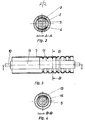
- the device for carrying out the method according to the invention consists of two simultaneously rotating lathe chucks 11 for clamping and rotating the glass tube 5 to be formed, centering tips 10 for fixed clamping of the inner forming tool 1 and associated heat sources, a 1st gas burner 15 and a multi-flame box burner 16 for heating the glass tube 5 to be formed to the required working temperature.
- the tube 5 to be formed from rasotherm glass is clamped at both ends with the aid of suitable clamping pieces 17 into the two simultaneously rotating lathe chucks 11, for example a glassmaking lathe.
- the inner forming tool 1, which consists of a special steel alloy, is sprayed with a non-stick agent and is located inside the glass tube 5 to be formed.
- This inner forming tool 1 is between centered, non-rotating tips 10, which are located in the center of the two lathe chucks 11, firmly clamped. On its outer surface lying against the inner wall of the glass tube 5 to be formed, it has the bead shape required for the inner tube 5 of the special gas discharge tube.
- the outer forming tool 6 made of graphite is displaceable and tiltable parallel to the axis of rotation of the pipe 5 to be formed, so that it can be pressed onto the circumference of the pipe 5 to be formed with moderate pressure force and, due to the static friction that occurs, performs an inevitable rotary movement about its axis of rotation.
- Its outer jacket has two beads with a shape complementary to the inner forming tool 1.
- the slowly rotating glass tube 5 is brought to such a high temperature with the aid of the first gas burner 15 that it can be plastically deformed.
- the first two beads are formed on the circumference of the tube with the help of the outer forming tool 6 by varying the pressing force.
- the outer forming tool 6 is lifted out of the beads and pushed further in the working direction by the amount of one bead.
- both the first molded-in bead and the inner shaping tool in the area of this first bead are kept at a predetermined high temperature, which is slightly below the transformation range of the Rasotherm glass.
- the rasotherm glass is again heated with the help of the first gas burner 15 to such an extent that it can be plastically deformed.
- the next bead is shaped in the form already described, the rear bead of the outer forming tool 6, viewed in the working direction, engaging in the second bead formed in the previous work step and being guided therein.
- the fourth and all subsequent beads are produced analogously.
- the glass tube 5 to be formed is kept during the entire machining process and also the inner forming tool 1 in the area of the beads which have already been formed at the temperature already specified below the transformation area of the Rasotherm glass.
- the inner shaping tool 1 is dismantled and removed from the glass tube, so that the fully shaped inner tube 5 can be cooled in a known manner without stress.
- the inner forming tool 1 is formed from three longitudinal parts which are connected to one another by a screw connection 12.
- a central part 2 with a rectangular cross section and an upper and lower part 3; 4, in the circular outer jacket of which the bead shape required for the inner tube 5 of the special gas discharge tube is incorporated.
- the inner shaping tool 1 has a circular cross-section, whose sides are flattened secant perpendicular, wherein the lateral spacing of the flats on the wall of the glass tube to be formed in shaft height 5 is about 1/3 of tube radius.
- the inner forming tool 1 is inserted over the entire length into the glass tube 5 to be formed and clamped by means of non-rotating centering tips 10 in such a way that it with its corrugated outer shells in a so-called clearance fit above and below the tube axis symmetrically on the associated circular segments of the inner wall of the area to be formed Glass tube 5 is present.
- the screw connections 12 are loosened, first the middle part 2 is pulled out and then the upper and lower part 3; 4 lowered or raised until they are released in the axial direction from the shaped beads of the finished tube and can also be removed.
- the one-piece inner forming tool 13 is fixedly arranged on a shaft 14, which in turn is clamped by means of longitudinally displaceable, non-rotating, lowerable centering tips 10.
- the shaft 14 can be lowered with the one-piece inner forming tool 13 by means of the centering tips 10 by an amount which is somewhat greater than the depth of the beads to be formed.
- the bead shape required for the inner tube 5 of the special gas discharge tube is incorporated.
- the one-piece inner forming tool 13 is introduced into the glass tube 5 in such a way that its outer jacket rests symmetrically above the tube axis on a circle segment on the inner wall of the glass tube 5 to be formed in an area which approximately corresponds to its radius .
- the shaft 14 is lowered with the one-piece inner shaping tool 13 by the amount mentioned, moved in the same direction as the outer shaping tool 6 by the amount of a bead in the working direction and raised again, so that always the rear bead of the one-piece shaping tool 13 seen in the working direction engages in the bead formed in the respective previous work step when the next bead is formed.
Landscapes
- Chemical & Material Sciences (AREA)
- Engineering & Computer Science (AREA)
- Materials Engineering (AREA)
- Organic Chemistry (AREA)
- Re-Forming, After-Treatment, Cutting And Transporting Of Glass Products (AREA)
- Lasers (AREA)
- Crystals, And After-Treatments Of Crystals (AREA)
Applications Claiming Priority (2)
| Application Number | Priority Date | Filing Date | Title |
|---|---|---|---|
| DD83249730A DD233747A3 (de) | 1983-04-11 | 1983-04-11 | Verfahren und einrichtung zur herstellung eines transversal gesickten oder gerippten inneren rohres einer doppelwandigen spezialgasentladungsroehre hoher winkelselektivitaet |
| DD249730 | 1983-04-11 |
Publications (2)
| Publication Number | Publication Date |
|---|---|
| EP0121941A1 EP0121941A1 (de) | 1984-10-17 |
| EP0121941B1 true EP0121941B1 (de) | 1987-07-15 |
Family
ID=5546365
Family Applications (1)
| Application Number | Title | Priority Date | Filing Date |
|---|---|---|---|
| EP84104069A Expired EP0121941B1 (de) | 1983-04-11 | 1984-04-11 | Verfahren und Einrichtung zur Herstellung eines transversal gesickten oder gerippten inneren Rohres einer doppelwandigen Spezial-Gasentladungsröhre hoher Winkelselektivität |
Country Status (8)
| Country | Link |
|---|---|
| US (1) | US4514206A (cs) |
| EP (1) | EP0121941B1 (cs) |
| JP (1) | JPS59189690A (cs) |
| BG (1) | BG49096A1 (cs) |
| CS (1) | CS255532B1 (cs) |
| DD (1) | DD233747A3 (cs) |
| DE (1) | DE3464753D1 (cs) |
| IN (1) | IN159912B (cs) |
Families Citing this family (7)
| Publication number | Priority date | Publication date | Assignee | Title |
|---|---|---|---|---|
| US4582523A (en) * | 1984-12-06 | 1986-04-15 | Gte Products Corporation | Method for manufacturing a discharge lamp envelope having multiple constrictions |
| US4585468A (en) * | 1984-12-06 | 1986-04-29 | Gte Products Corporation | Apparatus for manufacturing a discharge lamp envelope having multiple constrictions |
| US6180954B1 (en) * | 1997-05-22 | 2001-01-30 | Eaton Corporation | Dual-walled exhaust tubing for vacuum pump |
| DE102010045094B4 (de) * | 2010-09-13 | 2013-03-07 | Schott Ag | Verfahren und Vorrichtung zur lasergestützten Glasformung |
| US9027365B2 (en) * | 2013-01-08 | 2015-05-12 | Heraeus Quartz America Llc | System and method for forming fused quartz glass |
| DE102016114104A1 (de) | 2016-07-29 | 2018-02-01 | Schott Ag | Verfahren zur lasergestützen Umformung von Glaskörpern |
| CN108474110B (zh) * | 2016-12-12 | 2020-10-20 | 应用材料公司 | 用于在真空沉积工艺中保持基板的设备、用于在基板上进行层沉积的系统和用于保持基板的方法 |
Family Cites Families (5)
| Publication number | Priority date | Publication date | Assignee | Title |
|---|---|---|---|---|
| US2735230A (en) * | 1956-02-21 | Morrill | ||
| DE1068389B (cs) * | 1953-10-21 | 1959-11-05 | ||
| US2822501A (en) * | 1955-01-10 | 1958-02-04 | Research Corp | Slow-wave guide for traveling wave tubes |
| US3849531A (en) * | 1968-08-19 | 1974-11-19 | Coherent Radiation Labor Inc | Method of making a cored laser tube |
| DE2807596A1 (de) * | 1978-02-22 | 1979-08-30 | Qvf Glastech Gmbh | Verfahren und vorrichtung zum kalibrieren von glasrohrabschnitten |
-
1983
- 1983-04-11 DD DD83249730A patent/DD233747A3/de not_active IP Right Cessation
- 1983-12-20 JP JP58239017A patent/JPS59189690A/ja active Pending
-
1984
- 1984-01-05 US US06/573,895 patent/US4514206A/en not_active Expired - Fee Related
- 1984-03-06 IN IN162/CAL/84A patent/IN159912B/en unknown
- 1984-03-23 BG BG64797A patent/BG49096A1/xx unknown
- 1984-03-28 CS CS842248A patent/CS255532B1/cs unknown
- 1984-04-11 EP EP84104069A patent/EP0121941B1/de not_active Expired
- 1984-04-11 DE DE8484104069T patent/DE3464753D1/de not_active Expired
Also Published As
| Publication number | Publication date |
|---|---|
| DE3464753D1 (en) | 1987-08-20 |
| EP0121941A1 (de) | 1984-10-17 |
| CS255532B1 (en) | 1988-03-15 |
| CS224884A1 (en) | 1987-01-15 |
| US4514206A (en) | 1985-04-30 |
| JPS59189690A (ja) | 1984-10-27 |
| DD233747A3 (de) | 1986-03-12 |
| BG49096A1 (en) | 1991-08-15 |
| IN159912B (cs) | 1987-06-13 |
Similar Documents
| Publication | Publication Date | Title |
|---|---|---|
| EP3351313B1 (de) | Verfahren und vorrichtung zum drückwalzen | |
| EP0970765B1 (de) | Verfahren zum Umformen eines Werkstücks durch Drückwalzen | |
| EP0882532B1 (de) | Drückwalzvorrichtung und Verfahren zur Herstellung eines planverzahnten Werkstückes | |
| DE3432443A1 (de) | Schlauchpresshuelse | |
| DE19960582A1 (de) | Verfahren und Vorrichtung zum Drückwalzen | |
| DE19620812B4 (de) | Verfahren zum Herstellen eines rotationssymmetrischen Körpers | |
| WO1998006521A1 (de) | Verfahren und vorrichtung zur herstellung eines aussen verzahnten getriebeteiles | |
| DE2139054A1 (de) | Verfahren und Vorrichtung zur Materialverteilung an einem dünnwandigen Metallkörper | |
| DE3718884C2 (de) | Vorrichtung zum Herstellen von schrägverzahnten Werkstücken aus Metall, vorzugsweise Stahl | |
| EP0955110B1 (de) | Verfahren zum Drückwalzen und Drückwalzvorrichtung | |
| EP3436208B1 (de) | Verfahren zur herstellung eines eine nabe aufweisenden formkörpers sowie vorrichtung zur durchführung des verfahrens | |
| EP0590188B1 (de) | Presswerkzeug | |
| EP0121941A1 (de) | Verfahren und Einrichtung zur Herstellung eines transversal gesickten oder gerippten inneren Rohres einer doppelwandigen Spezial-Gasentladungsröhre hoher Winkelselektivität | |
| DD137537B1 (de) | Verfahren zur herstellung eines dickwandigen rotationssymetrischen metallhohlkoerpers | |
| DE4410146A1 (de) | Verfahren und Vorrichtung zur Herstellung von Pressfittings | |
| DE19725453C2 (de) | Verfahren zur Herstellung einer Hohlwelle | |
| EP0344570A2 (de) | Verfahren zur Herstellung einer Rohrwendel sowie Vorrichtung hierzu | |
| DE2320336B2 (de) | Vorrichtung zur spanlosen Herstellung von Kegelzahnrädern aus Metallrohteilen | |
| DE102008037549B3 (de) | Verfahren und Vorrichtung zur Herstellung eines rohrförmigen Werkstücks | |
| DE69101994T2 (de) | Verfahren und Vorrichtung zum Formen einer kreisförmigen Lippe um eine Öffnung. | |
| DE19913091A1 (de) | Mehrstufige Riemenscheibe sowie Verfahren zu ihrer Herstellung | |
| DE19716383C2 (de) | Verfahren zur Herstellung von rotationssymmetrischen Hohlkörpern | |
| EP0555631B1 (de) | Verfahren zur Herstellung eines aussen verzahnten Getriebeteiles | |
| DE19801491A1 (de) | Verfahren und Vorrichtung zur Herstellung von Hohlkörpern durch Querwalzen | |
| DE19635152A1 (de) | Verfahren und Vorrichtung zur Herstellung eines außen verzahnten Getriebeteiles |
Legal Events
| Date | Code | Title | Description |
|---|---|---|---|
| PUAI | Public reference made under article 153(3) epc to a published international application that has entered the european phase |
Free format text: ORIGINAL CODE: 0009012 |
|
| AK | Designated contracting states |
Designated state(s): CH DE LI NL |
|
| 17P | Request for examination filed |
Effective date: 19850220 |
|
| 17Q | First examination report despatched |
Effective date: 19860221 |
|
| GRAA | (expected) grant |
Free format text: ORIGINAL CODE: 0009210 |
|
| AK | Designated contracting states |
Kind code of ref document: B1 Designated state(s): CH DE LI NL |
|
| REF | Corresponds to: |
Ref document number: 3464753 Country of ref document: DE Date of ref document: 19870820 |
|
| PLBE | No opposition filed within time limit |
Free format text: ORIGINAL CODE: 0009261 |
|
| STAA | Information on the status of an ep patent application or granted ep patent |
Free format text: STATUS: NO OPPOSITION FILED WITHIN TIME LIMIT |
|
| 26N | No opposition filed | ||
| PGFP | Annual fee paid to national office [announced via postgrant information from national office to epo] |
Ref country code: NL Payment date: 19900430 Year of fee payment: 7 |
|
| PG25 | Lapsed in a contracting state [announced via postgrant information from national office to epo] |
Ref country code: NL Effective date: 19911101 |
|
| NLV4 | Nl: lapsed or anulled due to non-payment of the annual fee | ||
| PGFP | Annual fee paid to national office [announced via postgrant information from national office to epo] |
Ref country code: DE Payment date: 19970414 Year of fee payment: 14 |
|
| PG25 | Lapsed in a contracting state [announced via postgrant information from national office to epo] |
Ref country code: DE Free format text: LAPSE BECAUSE OF NON-PAYMENT OF DUE FEES Effective date: 19990401 |
|
| PGFP | Annual fee paid to national office [announced via postgrant information from national office to epo] |
Ref country code: CH Payment date: 19990429 Year of fee payment: 16 |
|
| PG25 | Lapsed in a contracting state [announced via postgrant information from national office to epo] |
Ref country code: LI Free format text: LAPSE BECAUSE OF NON-PAYMENT OF DUE FEES Effective date: 20000430 Ref country code: CH Free format text: LAPSE BECAUSE OF NON-PAYMENT OF DUE FEES Effective date: 20000430 |
|
| REG | Reference to a national code |
Ref country code: CH Ref legal event code: PL |