EP0121784A1 - Kopiermodul für ein elektrophotographisches Gerät - Google Patents
Kopiermodul für ein elektrophotographisches Gerät Download PDFInfo
- Publication number
- EP0121784A1 EP0121784A1 EP84102523A EP84102523A EP0121784A1 EP 0121784 A1 EP0121784 A1 EP 0121784A1 EP 84102523 A EP84102523 A EP 84102523A EP 84102523 A EP84102523 A EP 84102523A EP 0121784 A1 EP0121784 A1 EP 0121784A1
- Authority
- EP
- European Patent Office
- Prior art keywords
- chamber
- charging
- head
- exposing
- fixing
- Prior art date
- Legal status (The legal status is an assumption and is not a legal conclusion. Google has not performed a legal analysis and makes no representation as to the accuracy of the status listed.)
- Granted
Links
Images

Classifications
-
- G—PHYSICS
- G03—PHOTOGRAPHY; CINEMATOGRAPHY; ANALOGOUS TECHNIQUES USING WAVES OTHER THAN OPTICAL WAVES; ELECTROGRAPHY; HOLOGRAPHY
- G03G—ELECTROGRAPHY; ELECTROPHOTOGRAPHY; MAGNETOGRAPHY
- G03G15/00—Apparatus for electrographic processes using a charge pattern
- G03G15/22—Apparatus for electrographic processes using a charge pattern involving the combination of more than one step according to groups G03G13/02 - G03G13/20
- G03G15/221—Machines other than electrographic copiers, e.g. electrophotographic cameras, electrostatic typewriters
- G03G15/223—Machines for handling microimages, e.g. microfilm copiers
Definitions
- the present invention relates to a process or processing head for electrophotographic apparatus for recording picture image data on electrophotosensitive material by processing the same in various stages, i.e. charging/exposure, developing, drying and fixing, and more particularly to a process head which is easy to maintain and compact in size.
- Picture image data is generally recorded on a microfilm or the like by a 5-stage processing which comprises charging, exposing, developing, drying and fixing in a wet-type electrophotographic recording system.
- a film or an electro-photosensitive material is charged on the surface thereof by corona discharge in the charging process and forwarded to an exposing process.
- picture image data to be recorded is projected and recorded on the film via an optical system as an electrostatic latent image.
- the film with the electrostatic latent image is fed to a developing process where a developer is applied to the photosensitive surface thereof, and toner is electrically adhered according to the pattern of the latent image. Then, the film is passed to the drying process to dry unnecessary developer.
- the toner which has been electrically adhered is fused in a fixing process, thereby recording the picture image data on the film almost permanently. If a special liquid developer is used, it may be dried and fixed simultaneously. In such a case, the drying process includes the fixing process, and the film may be finished completely by a 4-stage process.
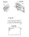
- a conventional head is shown in Figs. l(a) and l(b).
- the recording head 10 in Fig. l(a) is provided with a charging/exposing section 11, a fixing section 12 adjacent thereto, a liquid-removing section 13 and a developing section 11 arranged in that order; all these sections other than the liquid-removing section 13 have openings of a size corresponding to a frame of a film.
- a frame of the film is uniformly charged and projected with image at the charging/exposing section 11, then passed to the developing section 14 via the fixing section 12 and the liquid-removing section 13 and processed for development. It then is reversed to be passed in the direction toward the liquid-removing section 13 to remove the liquid and dry while moving toward the fixing section 12.
- the fixing process is conducted in section 12, and at the same time a new frame adjacent to the first frame is charged and exposed at the charging/exposing section 11.
- the recording head 20 shown in Fig. l(b) is an example where a main body 21 is provided to be slidable in the advancing direction of the film and to comprise a developing section 22, an exposing section 23, a charging section 24, and a drying section 25 arranged in proper order.
- the main body 21 is moved in the advancing direction of the film toward a frame thereof which is held stationary at a predetermined position, to conduct processes from charging to developing consecutively by the charging section 24, the exposing section 23, and the developing section 22. Then, the main body 21 is reversed in movement so that the drying section 25 comes to face the frame to conduct drying and fixing operations.
- Fig. l(a) there are US Pat. No. 3,972,610 and No. 4,082,442,etc.
- Fig. l(b) there is Jap. Pat. Pub. Sho 54-13786.
- the conventional process heads for recording have a common defect of a complex feeding mechanism because the relative moving direction of the head must be reversed after developing. Also, these heads are detrimental to efficiency in processing, because a plurality of processes cannot be conducted simultaneously and the intervals between processes tend to become extended. Further, the process head for recording shown in Fig. l(a) has the drawback that, since a pressure reducing pump is used for feeding the developer into the developing chamber, the structure of the liquid flow system becomes complicated and thus expensive.
- the present invention aims to provide a process head for electrophotographic apparatus for recording picture image data on electro-photosensitive material, which is easy to maintain and compact in size.
- the process head which comprises a charging/exposing chamber, a developing chamber, a drying chamber and a fixing chamber
- the process head is characterized in that at least the portion of the charging/exposing chamber where a corona wire is fixed, is detachably mounted.
- Another object of the present invention is to provide a process head which is more easy to maintain and assemble.
- This process head comprises a member for mounting and a head member and is characterized in that:
- the present invention aims to propose a compact construction of a process or processing head for electrophotographic apparatus, which is not only capable of continuous processing of electrophotographs in a wet-type electrophotographic recording system,but also is easy to repair, inspect and maintain.
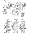
- the process head comprises a mounting member 112 and head members 114 and 115.
- the mounting member 112 is adapted to be mounted to the main body of an electrophotographic apparatus (not shown), and provided with recessed portions 112a and 112b where each processing chamber will be formed when the head members 114 and 115 are attached thereto.
- Said recessed portions 112a and 112b are formed on both sides of the mounting member 112, and the latter is divided into two sections by these recessed portions 112a and 112b.
- a lens 111 for exposure or projection is screwed to the recessed portion at the left in Fig.
- a drying air supply path 113 is formed in said mounting member 112 to blow air for drying onto the electro-photosensitive material located at the drying stage to be described hereinbelow. All the components may be either screwed or bonded to the mounting member 112.
- the above head portions are provided with openings for respective processing chambers to constitute a charging/ exposing window 116, a developing window 120 and a fixing window 129 which face the electro-photosensitive material. These openings in the charging/exposing chamber,developing chamber, drying chamber and fixing chamber, respectively, are conformed in size to one frame of the electro-photosensitive material, and arranged in a row or line starting from the charging/exposing chamber in the above order.
- the head member 114 comprises a complex stage head 114 which includes portions for the charging/exposing stage, the developing stage and the drying stage, and a single stage head member 115 which is associated only with the fixing stage.
- the construction of the head is not limited to that described above, but may be different so long as at least two or more stage heads each having said processing chambers,are formed and arranged in a row.
- the construction of the charging/exposing stage is shown in section in Fig. 5. As illustrated, a charging/ exposing window 116 is formed in the complex stage head 114 at its charging/exposing stage to oppose the lens 111.
- a detachable charging head 119 which opposes the electro-photosensitive material 117 and which is provided with a corona wire 118 for charging said material, fits in the mounting member 112 in a manner to be held between the latter and the complex stage head 114.
- the charging mechanism shown in this embodiment and comprising the corona wire 118 and corona electrodes l18a on both sides of the wire is made detachable, any form of mechanism may be used so long as the corona wire 118 is detachable or removable.
- the configuration of the mounting member 112 and of the charging head 119 is not limited to the one shown in the above embodiment so long as the charging head 119 can be attached to the mounting member 112 as complex stage head 114.
- the complex stage head 114 is formed with a developing window 20 adjacent to the charging/exposing window 116.
- a developer supply path 121 is provided above the window 120, and a suction path 122 is provided below the window 120 to remove excess developer remaining on the surface of the electro-photosensitive material 117 after developing.
- a partition 123 which projects toward the developing window 120 is integrally fixed by adhesion or fusion to the rear of the complex stage head 114 at the developing stage.
- the developing chamber 124 is formed between said partition 123 and the developing window 120.
- the partition 123 is provided with a squeezing-air supply path 125 and a discharge path 126 for discharging excess developer and squeezing air.
- the developer supplied via the developer supply path 121, or the air blown in via the air supply path 125 flows through the developing chamber 124 and is discharged through the discharge path 126.
- drying air supplied from the drying air supply path 113 is blown on the electro-photosensitive material 117 positioned at this portion.
- a guide plate 127 is screwed to the mounting member 112 to guide the drying air from the air supply path 113 toward the electro-photosensitive material 117.
- Fig. 8 a guide plate 127 is screwed to the mounting member 112 to guide the drying air from the air supply path 113 toward the electro-photosensitive material 117.
- a window for fixing 129 having a protective glass 128 adhered there-across is formed in the single stage head 115 which is screwed to the mounting member 112.
- a detachable Xenon flash light tube 130 is inserted between the single stage head 115 and the mounting member 112 and shielded from outside by means of a pair of shielding plates 131 which are screwed to the mounting member 112 and the single stage head 115.
- the complex (or multiple) stage head 114 and the single stage head 115 are provided separately in this embodiment, they may be formed as an integral component. It is also noted that any known means for charging, drying or fixing other than those employed in this embodiment can be used.
- a press plate 32 is provided at each stage to retain the electro-photosensitive material 117 flat.
- the device operates in the same manner as the conventional device for recording data.
- the charging/ exposing stage, developing stage, drying stage and fixing stage are located in this order at an interval corresponding to one frame of the electro-photosensitive material 117, and the latter is advanced intermittently frame by frame, so that the required picture image data are consecutively recorded on the material 117.
- the charging head 119 if it requires inspection/maintenance and repair/replacement due to failure, can be easily detached from the mounting member 112 by removing the screws. Likewise, the Xenon flash light tube 130 can also be easily detached. There is no risk of varying the distance between the lens 11 and the electro-photosensitive material 117 in operation, and thus there is less risk of lowering the precision by attaching/ detaching the charging head 119.
- a large space is formed at the rear of the developing chamber 124, where the portion of the charging head 119 holding the corona wire can be installed so as to minimize the spacing between the charging/exposing stage and the developing stage, thereby making the head compact as a whole
- the charging section can be separately attached/detached arbitrarily in the process head according to the present invention, inspection, maintenance or repair thereof can be performed promptly as well as easily.
Landscapes
- Physics & Mathematics (AREA)
- General Physics & Mathematics (AREA)
- Combination Of More Than One Step In Electrophotography (AREA)
- Wet Developing In Electrophotography (AREA)
Applications Claiming Priority (2)
| Application Number | Priority Date | Filing Date | Title |
|---|---|---|---|
| JP36581/83 | 1983-03-08 | ||
| JP58036581A JPS59162580A (ja) | 1983-03-08 | 1983-03-08 | 電子写真装置用プロセスヘツド |
Publications (2)
| Publication Number | Publication Date |
|---|---|
| EP0121784A1 true EP0121784A1 (de) | 1984-10-17 |
| EP0121784B1 EP0121784B1 (de) | 1987-11-25 |
Family
ID=12473733
Family Applications (1)
| Application Number | Title | Priority Date | Filing Date |
|---|---|---|---|
| EP84102523A Expired EP0121784B1 (de) | 1983-03-08 | 1984-03-08 | Kopiermodul für ein elektrophotographisches Gerät |
Country Status (4)
| Country | Link |
|---|---|
| US (1) | US4697912A (de) |
| EP (1) | EP0121784B1 (de) |
| JP (1) | JPS59162580A (de) |
| DE (1) | DE3467823D1 (de) |
Cited By (1)
| Publication number | Priority date | Publication date | Assignee | Title |
|---|---|---|---|---|
| EP0153422B1 (de) * | 1984-02-09 | 1988-05-25 | Fuji Photo Film Co., Ltd. | Elektrophotographische Vorrichtung |
Families Citing this family (4)
| Publication number | Priority date | Publication date | Assignee | Title |
|---|---|---|---|---|
| JPS6370272A (ja) * | 1986-09-11 | 1988-03-30 | Fuji Photo Film Co Ltd | 電子写真装置用フイルム押圧手段 |
| US5198195A (en) * | 1987-12-28 | 1993-03-30 | Fuji Photo Film Co., Ltd. | Developer treatment apparatus |
| US5294406A (en) * | 1988-11-02 | 1994-03-15 | Fuji Photo Film Co., Ltd. | Waste solution treatment apparatus |
| DE4130564A1 (de) * | 1991-09-13 | 1993-03-18 | Agfa Gevaert Ag | Vorrichtung zum fuehren von fotografischen filmen |
Citations (4)
| Publication number | Priority date | Publication date | Assignee | Title |
|---|---|---|---|---|
| DE2036140B2 (de) * | 1969-07-21 | 1973-10-18 | Fuji Photo Film Co. Ltd., Ashigara, Kanagawa (Japan) | Elektrophotographisches Kopiergerat |
| US4006986A (en) * | 1973-08-17 | 1977-02-08 | Coulter Information Systems, Inc. | Image recording apparatus for electrophotographic film |
| GB1540230A (en) * | 1973-12-12 | 1979-02-07 | Addressograph Multigraph | Electrophotographic imaging methods |
| DE2416521B2 (de) * | 1973-04-09 | 1980-03-20 | A.B. Dick Co., Chicago, Ill. (V.St.A.) | Elektrofotografische Vorrichtung zum Herstellen von Reproduktionen auf einer Vielzahl von in Reihe und Spalten angeordneten Mikrobildfeldern |
Family Cites Families (7)
| Publication number | Priority date | Publication date | Assignee | Title |
|---|---|---|---|---|
| US3528355A (en) * | 1967-09-01 | 1970-09-15 | Xerox Corp | Camera-processor |
| BE788894A (fr) * | 1971-09-17 | 1973-01-02 | Siemens Ag | Couche electriquement conductrice sur base de forte resistivite, procede de fabrication et application d'une telle couchecomme resistance electrique |
| ZA733190B (en) * | 1972-06-08 | 1974-04-24 | Coulter Information Systems | Method and apparatus for recording images on electro-photographic film |
| US3964828A (en) * | 1972-12-29 | 1976-06-22 | Ricoh Co., Ltd. | Apparatus for preparing electrophotographic microfilm |
| JPS5077043A (de) * | 1973-12-24 | 1975-06-24 | ||
| JPS5530235B2 (de) * | 1975-02-05 | 1980-08-09 | ||
| JPS5785071A (en) * | 1980-11-17 | 1982-05-27 | Matsushita Electric Ind Co Ltd | Recorder |
-
1983
- 1983-03-08 JP JP58036581A patent/JPS59162580A/ja active Pending
-
1984
- 1984-03-08 EP EP84102523A patent/EP0121784B1/de not_active Expired
- 1984-03-08 DE DE8484102523T patent/DE3467823D1/de not_active Expired
-
1986
- 1986-07-21 US US06/885,748 patent/US4697912A/en not_active Expired - Lifetime
Patent Citations (4)
| Publication number | Priority date | Publication date | Assignee | Title |
|---|---|---|---|---|
| DE2036140B2 (de) * | 1969-07-21 | 1973-10-18 | Fuji Photo Film Co. Ltd., Ashigara, Kanagawa (Japan) | Elektrophotographisches Kopiergerat |
| DE2416521B2 (de) * | 1973-04-09 | 1980-03-20 | A.B. Dick Co., Chicago, Ill. (V.St.A.) | Elektrofotografische Vorrichtung zum Herstellen von Reproduktionen auf einer Vielzahl von in Reihe und Spalten angeordneten Mikrobildfeldern |
| US4006986A (en) * | 1973-08-17 | 1977-02-08 | Coulter Information Systems, Inc. | Image recording apparatus for electrophotographic film |
| GB1540230A (en) * | 1973-12-12 | 1979-02-07 | Addressograph Multigraph | Electrophotographic imaging methods |
Cited By (1)
| Publication number | Priority date | Publication date | Assignee | Title |
|---|---|---|---|---|
| EP0153422B1 (de) * | 1984-02-09 | 1988-05-25 | Fuji Photo Film Co., Ltd. | Elektrophotographische Vorrichtung |
Also Published As
| Publication number | Publication date |
|---|---|
| DE3467823D1 (en) | 1988-01-07 |
| EP0121784B1 (de) | 1987-11-25 |
| US4697912A (en) | 1987-10-06 |
| JPS59162580A (ja) | 1984-09-13 |
Similar Documents
| Publication | Publication Date | Title |
|---|---|---|
| US6219504B1 (en) | Process cartridge and image forming apparatus | |
| EP0121784B1 (de) | Kopiermodul für ein elektrophotographisches Gerät | |
| EP0153422B1 (de) | Elektrophotographische Vorrichtung | |
| EP0931281B1 (de) | Bilderzeugungsgerät | |
| US8270867B2 (en) | Image forming apparatus and process cartridge | |
| US4461561A (en) | Apparatus for imaging and developing electrophotographic microformats | |
| US3219326A (en) | Xerographic fusing apparatus | |
| JPH0339799Y2 (de) | ||
| US3450474A (en) | Record copier | |
| JPS58190967A (ja) | 画像形成装置 | |
| US20060104658A1 (en) | Image forming apparatus | |
| US3072026A (en) | Automatic contact printers for electrostatic reproductions | |
| EP0497374A2 (de) | Elektrofotographische Vorrichtung | |
| US3754137A (en) | Corona discharge device | |
| US4788576A (en) | Microfilm duplicating apparatus | |
| JPS6275657A (ja) | 画像形成装置 | |
| JPH0326837B2 (de) | ||
| JPS6063528A (ja) | 静電複写装置 | |
| JPH0317308Y2 (de) | ||
| JPH10198238A (ja) | 画像形成装置 | |
| JP2003195514A (ja) | 電子製版機 | |
| JPH05281823A (ja) | 画像形成装置 | |
| JP2002225338A (ja) | 発光装置、その取付方法及び画像形成装置 | |
| JPS6063530A (ja) | 静電複写装置における光学系 | |
| JPH0543162U (ja) | 電子写真装置 |
Legal Events
| Date | Code | Title | Description |
|---|---|---|---|
| PUAI | Public reference made under article 153(3) epc to a published international application that has entered the european phase |
Free format text: ORIGINAL CODE: 0009012 |
|
| AK | Designated contracting states |
Designated state(s): DE FR GB |
|
| 17P | Request for examination filed |
Effective date: 19850415 |
|
| 17Q | First examination report despatched |
Effective date: 19860307 |
|
| RAP1 | Party data changed (applicant data changed or rights of an application transferred) |
Owner name: FUJI PHOTO FILM CO., LTD. |
|
| GRAA | (expected) grant |
Free format text: ORIGINAL CODE: 0009210 |
|
| AK | Designated contracting states |
Kind code of ref document: B1 Designated state(s): DE FR GB |
|
| REF | Corresponds to: |
Ref document number: 3467823 Country of ref document: DE Date of ref document: 19880107 |
|
| ET | Fr: translation filed | ||
| PLBE | No opposition filed within time limit |
Free format text: ORIGINAL CODE: 0009261 |
|
| STAA | Information on the status of an ep patent application or granted ep patent |
Free format text: STATUS: NO OPPOSITION FILED WITHIN TIME LIMIT |
|
| 26N | No opposition filed | ||
| REG | Reference to a national code |
Ref country code: GB Ref legal event code: IF02 |
|
| PGFP | Annual fee paid to national office [announced via postgrant information from national office to epo] |
Ref country code: FR Payment date: 20020318 Year of fee payment: 19 |
|
| PGFP | Annual fee paid to national office [announced via postgrant information from national office to epo] |
Ref country code: DE Payment date: 20020529 Year of fee payment: 19 |
|
| PGFP | Annual fee paid to national office [announced via postgrant information from national office to epo] |
Ref country code: GB Payment date: 20030212 Year of fee payment: 20 |
|
| PG25 | Lapsed in a contracting state [announced via postgrant information from national office to epo] |
Ref country code: DE Free format text: LAPSE BECAUSE OF NON-PAYMENT OF DUE FEES Effective date: 20031001 |
|
| PG25 | Lapsed in a contracting state [announced via postgrant information from national office to epo] |
Ref country code: FR Free format text: LAPSE BECAUSE OF NON-PAYMENT OF DUE FEES Effective date: 20031127 |
|
| REG | Reference to a national code |
Ref country code: FR Ref legal event code: ST |
|
| PG25 | Lapsed in a contracting state [announced via postgrant information from national office to epo] |
Ref country code: GB Free format text: LAPSE BECAUSE OF EXPIRATION OF PROTECTION Effective date: 20040307 |
|
| REG | Reference to a national code |
Ref country code: GB Ref legal event code: PE20 |