EP0153422B1 - Elektrophotographische Vorrichtung - Google Patents
Elektrophotographische Vorrichtung Download PDFInfo
- Publication number
- EP0153422B1 EP0153422B1 EP84101536A EP84101536A EP0153422B1 EP 0153422 B1 EP0153422 B1 EP 0153422B1 EP 84101536 A EP84101536 A EP 84101536A EP 84101536 A EP84101536 A EP 84101536A EP 0153422 B1 EP0153422 B1 EP 0153422B1
- Authority
- EP
- European Patent Office
- Prior art keywords
- chamber
- fixing
- charging
- electro
- opening
- Prior art date
- Legal status (The legal status is an assumption and is not a legal conclusion. Google has not performed a legal analysis and makes no representation as to the accuracy of the status listed.)
- Expired
Links
- 238000001035 drying Methods 0.000 claims description 45
- 238000007600 charging Methods 0.000 claims description 44
- 238000000034 method Methods 0.000 claims description 41
- 239000000463 material Substances 0.000 claims description 31
- 230000007246 mechanism Effects 0.000 claims description 16
- 239000007788 liquid Substances 0.000 claims description 12
- 238000005192 partition Methods 0.000 claims description 8
- 230000003068 static effect Effects 0.000 claims description 5
- 238000010276 construction Methods 0.000 claims description 3
- 239000000126 substance Substances 0.000 claims description 3
- 229910052724 xenon Inorganic materials 0.000 claims description 3
- FHNFHKCVQCLJFQ-UHFFFAOYSA-N xenon atom Chemical compound [Xe] FHNFHKCVQCLJFQ-UHFFFAOYSA-N 0.000 claims description 3
- 229910052736 halogen Inorganic materials 0.000 claims description 2
- 150000002367 halogens Chemical class 0.000 claims description 2
- 230000000694 effects Effects 0.000 description 4
- 230000002411 adverse Effects 0.000 description 3
- 230000006866 deterioration Effects 0.000 description 2
- 230000003287 optical effect Effects 0.000 description 2
- 230000002093 peripheral effect Effects 0.000 description 2
- 238000010521 absorption reaction Methods 0.000 description 1
- 238000007664 blowing Methods 0.000 description 1
- 230000001627 detrimental effect Effects 0.000 description 1
- 230000005611 electricity Effects 0.000 description 1
- 239000011521 glass Substances 0.000 description 1
- 238000003384 imaging method Methods 0.000 description 1
- 238000004519 manufacturing process Methods 0.000 description 1
- 239000002985 plastic film Substances 0.000 description 1
- 229920006255 plastic film Polymers 0.000 description 1
- 239000012925 reference material Substances 0.000 description 1
- 238000004904 shortening Methods 0.000 description 1
- 229910052709 silver Inorganic materials 0.000 description 1
- 239000004332 silver Substances 0.000 description 1
- -1 silver halide Chemical class 0.000 description 1
Images


Classifications
-
- G—PHYSICS
- G03—PHOTOGRAPHY; CINEMATOGRAPHY; ANALOGOUS TECHNIQUES USING WAVES OTHER THAN OPTICAL WAVES; ELECTROGRAPHY; HOLOGRAPHY
- G03G—ELECTROGRAPHY; ELECTROPHOTOGRAPHY; MAGNETOGRAPHY
- G03G15/00—Apparatus for electrographic processes using a charge pattern
- G03G15/22—Apparatus for electrographic processes using a charge pattern involving the combination of more than one step according to groups G03G13/02 - G03G13/20
- G03G15/221—Machines other than electrographic copiers, e.g. electrophotographic cameras, electrostatic typewriters
- G03G15/223—Machines for handling microimages, e.g. microfilm copiers
-
- G—PHYSICS
- G03—PHOTOGRAPHY; CINEMATOGRAPHY; ANALOGOUS TECHNIQUES USING WAVES OTHER THAN OPTICAL WAVES; ELECTROGRAPHY; HOLOGRAPHY
- G03G—ELECTROGRAPHY; ELECTROPHOTOGRAPHY; MAGNETOGRAPHY
- G03G15/00—Apparatus for electrographic processes using a charge pattern
- G03G15/22—Apparatus for electrographic processes using a charge pattern involving the combination of more than one step according to groups G03G13/02 - G03G13/20
- G03G15/26—Apparatus for electrographic processes using a charge pattern involving the combination of more than one step according to groups G03G13/02 - G03G13/20 in which the charge pattern is obtained by projection of the entire image, i.e. whole-frame projection
Definitions
- This invention relates to an electrophotographic device having a process head which comprises four separate stages of charging/ exposure, developing, drying and fixing and which simultaneously processes a plurality of frames of a recording film.
- Picture image data is generally recorded on a microfilm or the like by a 5-stage processing which comprises charging, exposing, developing, drying and fixing in a wet-type electrophotographic recording system.
- a film or an electro-photosensitive material is charged on the surface thereof by corona-discharge in the charging process and forwarded to an exposing process.
- picture image data to be recorded is projected and recorded on the film via an optical system, as an electrostatic latent image.
- the film with the electrostatic latent image is fed to a developing process, where a developer is applied on the photosensitive surface thereof, and toner is electrically adhered according to the pattern of the latent image. Then, the film is passed to the drying process to dry unnecessary developer.
- the toner which has been electrically adhered is fused in a fixing process, thereby recording the picture image data on the film almost permanently. If a special liquid developer is used, it may be dried and fixed simultaneously. In such a case, the drying process includes the fixing process, and the film may be finished completely by a 4-stage process.
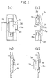
- a conventional recording head is shown in Figure 1 (a) and 1 (b).
- the recording head 10 in Figure 1(a) is provided with a charging/exposing section 11, a fixing section 12 adjacent thereto, a liquid-removing section 13 and a developing section 14 arranged in that order, and all the sections other than the liquid-removing section 13 have openings of a size corresponding to a frame of film.
- a frame of the film is uniformly charged and projected with an image at the charging/exposing section 11, then passed to the developing section 14 via the fixing section 12 and the liquid-removing section 13, and processed for development. It then is reversed to be passed in the direction toward the liquid-removing section 13 to remove the liquid and dry while moving toward the fixing section 12. Fixing process is conducted in the section, and at the same time a new frame adjacent to the first frame is charged and exposed at the charging/exposing section.
- the recording head 20 shown in Figure 1(b) is an example where a main body 21 is slidably provided in the advancing direction of the film and is comprised of a developing section 22, an exposing section 23, a charging section 24, and a drying section 25 arranged in due order.
- the main body 21 is moved in the advancing direction of the film toward a frame thereof which is held stationary at a predetermined position to conduct processes from charging to developing consecutively by the charging section 24, the exposing section 23, and the developing section 22. Then, the main body 21 is reversed in movement so that the drying section 25 comes to face the frame to conduct drying and fixing operations.
- FIG 1(a) there are relevant documents US-A-3,972,610 and US-A-4,082,442, etc.
- Figure 1(b) there are relevant documents JP-B-54-13786 and US-A-3964828.
- the conventional processing heads for recording have in common the drawback of a complex feeding mechanism because the relative moving direction of the head must be reversed after developing. Also, this structure is detrimental to efficiency in processing because a plurality of processes cannot be conducted simultaneously, and the intervals between processes tend to become extended. Further, the processing head for recording shown in Figure 1(a) has a drawback in that since a pressure reducing pump is used for feeding the developer into the developing chamber, the structure of the liquid passage system becomes complicated and thus expensive.
- Prior European application 84 102 v 523.2 discloses a processing head for an electrophotographic apparatus for microfilms, said processing head comprising adjacent to each other four processing chambers including a charging/exposing chamber, a developing chamber, a drying chamber and a fixing chamber.
- Each of said processing chambers has an opening abutting a plane in which electro-photosensitive material passes said processing head.
- the openings are arranged in the following order: charging/exposing chamber window, developing chamber window, drying chamber opening, and fixing chamber window in the direction of movement of the electro-photosensitive material, and the openings being spaced apart at intervals corresponding to the length of a frame of a picture image formed on the electro- photosensitive material.
- prior European application 83 113 080.2 discloses a developing head for an electrophotographic apparatus which comprises a developing mask having a developing chamber defined by a framed opening facing the photosensitive surface of an electrophotographic material for electrophotography. The mouth of the opening abuts on said photosensitive surface, and the outer peripheral surface of said developing mask opposes the photosensitive surface, which is contacted with the liquid developer supplied from a liquid feeding means via said developing chamber to achieve development of the electrophotographic material.
- a bent or curved portion is formed near the mouth of the framed opening to assume an angle greater than that formed between the rest of the outer peripheral surface of the developing mask with said electrophotographic material so that an interval can be formed to prevent the liquid developer from leaking through said bent portion and the electrophotographic material.
- An object of this invention is to provide a reliable electrophotographic device of low cost for an electrophotographic system comprising four sections of the stages of exposure, development, drying and fixing which are arranged at intervals equivalent to that between frames, so that while a process which takes a long time is being conducted, other processes may be conducted simultaneously, thereby saving time as a whole.
- the present invention provides an electrophotographic device having a process head for forming picture images on an electro-photosensitive material, wherein
- a press plate 38 is provided to face said housing 31. Said press plate is fixed by means of an arm 38b attached to a rotatable shaft 38a for the press plate. It is desirable that the structure allows the fixing point 38c to be movable and that the press plate 38 can come in contact with the surface of the process head 30.
- the press plate 38 is designed so as to press the film 37 closely against the process head 30 during processing, and to release the film when it is forwarded.
- Corona electrodes 33b are provided above an opening 33a inside said charging/exposing chamber 33. Said corona electrodes 33b act to generate corona discharge for charging the film surface at the opening 33a; a corona wire 33c is preferably provided between said corona electrodes 33b.
- a charging mask 33d is provided on the outer periphery of the opening 33a to restrict the charging field to the size of a frame.
- a high voltage is applied for corona discharge between elements 33c and 33b. Electrodes 33b are normally kept at a potential closer to ground.
- the charging mask 33d should be positioned as close as possible to the film surface and reduced in thickness in order to clearly define the discharge fields on the film. If a flexible material is used, it can be positioned closer to the film to achieve a higher efficiency.
- Reference numeral 33e denotes a bias electrode for charging which improves the uniformity of charging by applying a potential substantially equivalent to that of the photosensitive member.
- An exposing lens 33f is provided at a position opposite to the opening 33a in the charging/exposing chamber 33. The lens 33f acts'to focus picture image data of a text provided separately (not shown) through said opening 33a on the film 37 and expose it to the light.
- Figure 4(a) is a sectional view of the charging/ exposing section 33.
- a corona wire 33c is provided at the center, and a lens 33f for exposure and the opening 33a are substantially opposed on both sides of the corona wire 33c.
- a developing chamber 35 Next to said charging/exposing chamber 33 is provided a developing chamber 35.
- a feeding mechanism for a liquid developer is provided inside of said developing chamber 35, and an electrode for developing 39 is disposed on the side which comes to face the film 37.
- Figure 4(b) is a schematic cross-sectional view of the developing section.
- a cover 35a is provided inside said developing chamber 35, and an internal member 35b is positioned inside said cover 35a, thereby defining a supply route 35d and a discharge route 35e which run through the opening 35c.
- a liquid developer flows in from the outside through the supply route 35d to the opening section 35c to contact the film surface, and the toner is electrically adhered to the static latent image formed in said charging/exposing section 33.
- the developer after development is discharged through the discharge route 35e.
- the film is pressed onto the opening section 35c by the press plate 38 to prevent leakage of the developer.
- squeeze means to remove developer after the developing process and to improve the efficiency of the drying process subsequent thereto.
- There are many useful mechanisms such as (a) a corona squeeze, (b) an absorption mechanism, (c) a mechanism to suck liquid drops from the film surface with a piece of felt or capillary, (d) a mechanism for applying or blowing air or (e) a mechanism to supply hot air.
- Reference numeral 35f denotes an inlet for the air which is to be blown in.
- a suction slit 35g is provided to prevent damage to the image which may be caused as the developer leaks from the developing chamber 35 to seep into the adjacent processing chamber or other images on the film during developing or squeezing of the developer.
- the suction slit 35g is under reduced pressure as it is connected to a suction pump (not shown) via a suction pipe 35h. It is not necessary to provide the suction slit 35g over the entire periphery of the opening of the developing chamber so long as it is provided on at least one side thereof, for example, at the bottom or the side.
- a drying chamber 36 which is defined by a partition wall 40 opposing the film surface.
- the opening 36a of said drying chamber 36 has a size larger than that of the opening 35c of the developing chamber 35 and larger than the width of the film.
- Said drying chamber 36 is provided with a drying means to supply air or hot air to dry the remaining developer, or with any other known drying means.
- a squeezing means similar to the one mentioned hereinabove may be provided in the chamber.
- Figure 4(c) is a sectional view of the drying chamber, in which the drying air is applied or blown onto the film 37, as shown by the arrow in Figure 4(c).
- the drying air is applied or blown onto the film 37, as shown by the arrow in Figure 4(c).
- the partition 40 is preferably spaced from the film 37 by 2 mm or less in order to achieve said air speed.
- a fixing lamp 34b is provided inside a fixing section 34 positioned on the side of the housing 31 to extend toward the opening section 34a, while a reflection mirror 34c is provided behind said fixing lamp 34b.
- the fixing lamp 34b may be a xenon lamp, a halogen lamp or the like.
- a light transmissive member 34d such as a plastic film or glass, is provided between the fixing lamp 34b and the film 37, an adverse effect which is caused by a gassified substance at the time of fixing may be prevented.
- Such effect can be prevented effectively if the air is circulated between the film 37 and said light transmissive member 34d. It is further preferable to increase the distance between the film 37 and said light transmissive member 34d, because the light transmissive member can be protected from being soiled by scattering toner; specifically, this distance is more than 1 mm and, more preferably, 3 mm or more.
- a sectional view of the fixing chamber 34 is shown in Figure 4(d). The light transmissive member 34d, the fixing lamp 34b and the reflection mirror 34c are arranged in this order to oppose the opening 34a.
- partitions 32a, 32b and 32c are provided, the number of these partitions is variable depending on the mechanical strength, the method of manufacture, etc., of the process head 30.
- the feeding mechanism for photosensitive materials 37 which feeds or advances the materials by one frame may be a motor, such as a pulse motor, which is provided with a mechanism to feed a predetermined length of material, or a mechanism which positions a film by optically detecting marks which are provided on a film 37 at predetermined intervals.
- a motor such as a pulse motor, which is provided with a mechanism to feed a predetermined length of material, or a mechanism which positions a film by optically detecting marks which are provided on a film 37 at predetermined intervals.
- FIG. 5 shows one embodiment of an electrophotographic recording/reproduction system which utilizes the process head 30 of the present invention.
- a roll of film 37 of 16 mm in width is printed in advance with blip marks 50 for every frame pitch.
- the blip marks 50 are read by a blip mark sensor 51 for controlling the feed of the film 37 or counting the number of frames. It is more convenient if the film 37 is previously mounted in a cassette which is in turn inserted in an electrophotographic device having the process head of the present invention, so that the film can be used for recording/reproducing desired video data.
- the roll of film 37 contained in a cassette is provided with a magnetic tape at its leading end. As the cassette is inserted in the main body of the device, the retrieval data of the picture image recorded on the magnetic tape or the process data regarding the roll of film 37 can be read out by a magnetic head 52 provided on the main body of the device.
- the blip marks 50 of the film are counted by means of the blip mark sensor 51, and the frame to be photographed is forwarded to the charging/exposing chamber 33 by means of a film driving mechanism (not shown) provided on the main body of the device.
- a film driving mechanism not shown
- the film with the picture images can be projected on the screen by a separate device exclusively for reading.
- the picture image can also be focused on the screen (not shown) to be used as a reader, by projecting light onto the film 37 from behind the press plate 38, as shown in Figure 3, and by means of the exposure lens 33f.
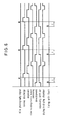
- FIG. 6 shows an example of the processing sequence in case that a large number of frames are continuously photographed. The operation will be described hereinunder.
- the film 37 When the first frame of the film 37 is aligned in front of opening 33a of the charging/exposing chamber 37, the film 37 is moved closely to, and positioned at, the opening 33a by the press plate 38. In response to a start signal, corona discharge is started to charge electricity uniformly over the portion where a picture image is to be formed, and then picture image data are focused via the exposing lens 33f.
- the press plate 38 When the press plate 38 is released, the film is forwarded by one frame, and when the first frame comes to be positioned at the opening of the developing chamber, it is pressed closely to the opening by the press plate 38 again.
- a developer is supplied by a feeding pump (not shown) or a suction pump (not shown) in a predetermined quantity to develop the electrostatic latent image, and then excessive liquid is squeezed or blown away by air. Although it is sufficient to actuate the suction slit 35g for suction only while the excessive liquid is dried by air, it may be actuated during all stages of the processing.
- the first frame is then moved to the opening of the drying chamber and is closely pressed by the press plate 38.
- the frame is dried by drying means provided in the drying chamber. After being dried, the film 37 is moved again by one frame to be positioned at the opening of the fixing chamber.
- the image is fixed by flashing of a xenon lamp, for instance, to complete the process.
- the processes for exposing, liquid-removing and drying take a longer time compared with other processes.
- the four stages are arranged in a recording head consecutively in a line so that, while a frame is being dried, other adjacent frames can be simultaneously processed, thereby remarkably reducing the overall processing time and shortening the time intervals between exposing for continuous imaging.
- the fixing operation with flash for a frame which is positioned at the fixing chamber should be conducted after the developing operation for another frame at the developing chamber has been completed, and before the charging operation for another frame positioned at the charging/exposing chamber is started (the period of t in Figure 5), to prevent deterioration which might otherwise be caused by the light leakage from the fixing lamp and to effectively reproduce a picture image of a high quality.
- This invention enables to finish such flashing fixation within the period t mentioned above, thereby offering a clear image.
Landscapes
- Physics & Mathematics (AREA)
- General Physics & Mathematics (AREA)
- Combination Of More Than One Step In Electrophotography (AREA)
- Wet Developing In Electrophotography (AREA)
Claims (13)
Priority Applications (3)
| Application Number | Priority Date | Filing Date | Title |
|---|---|---|---|
| US06/578,522 US4600291A (en) | 1984-02-09 | 1984-02-09 | Electro-photographic device with a processing head having multiple chambers |
| EP84101536A EP0153422B1 (de) | 1984-02-09 | 1984-02-15 | Elektrophotographische Vorrichtung |
| DE8484101536T DE3471532D1 (en) | 1984-02-15 | 1984-02-15 | Electrophotographic device |
Applications Claiming Priority (2)
| Application Number | Priority Date | Filing Date | Title |
|---|---|---|---|
| US06/578,522 US4600291A (en) | 1984-02-09 | 1984-02-09 | Electro-photographic device with a processing head having multiple chambers |
| EP84101536A EP0153422B1 (de) | 1984-02-09 | 1984-02-15 | Elektrophotographische Vorrichtung |
Publications (2)
| Publication Number | Publication Date |
|---|---|
| EP0153422A1 EP0153422A1 (de) | 1985-09-04 |
| EP0153422B1 true EP0153422B1 (de) | 1988-05-25 |
Family
ID=26091453
Family Applications (1)
| Application Number | Title | Priority Date | Filing Date |
|---|---|---|---|
| EP84101536A Expired EP0153422B1 (de) | 1984-02-09 | 1984-02-15 | Elektrophotographische Vorrichtung |
Country Status (2)
| Country | Link |
|---|---|
| US (1) | US4600291A (de) |
| EP (1) | EP0153422B1 (de) |
Families Citing this family (11)
| Publication number | Priority date | Publication date | Assignee | Title |
|---|---|---|---|---|
| JPS6292977A (ja) * | 1985-10-18 | 1987-04-28 | Fuji Photo Film Co Ltd | 電子写真装置用プロセスヘツド |
| JPS62187867A (ja) * | 1985-11-04 | 1987-08-17 | ベンソン,インコ−ポレイテツド | プロツタトナ−ステ−シヨン |
| JPS62148984A (ja) * | 1985-12-23 | 1987-07-02 | Fuji Photo Film Co Ltd | 電子写真装置用現像液供給装置 |
| DE3788456T2 (de) * | 1986-06-16 | 1994-04-07 | Fuji Photo Film Co Ltd | Mikrofilm-Duplikatgerät. |
| EP0263509A3 (de) * | 1986-10-08 | 1989-04-26 | Fuji Photo Film Co., Ltd. | Reinigungsverfahren |
| JPS63287876A (ja) * | 1987-05-20 | 1988-11-24 | Fuji Photo Film Co Ltd | 電子写真装置用プロセスヘツド |
| US5198195A (en) * | 1987-12-28 | 1993-03-30 | Fuji Photo Film Co., Ltd. | Developer treatment apparatus |
| JPH0220889A (ja) * | 1987-12-28 | 1990-01-24 | Fuji Photo Film Co Ltd | 現像処理装置 |
| US5294406A (en) * | 1988-11-02 | 1994-03-15 | Fuji Photo Film Co., Ltd. | Waste solution treatment apparatus |
| US5042159A (en) * | 1989-11-27 | 1991-08-27 | Leo Millen | Chalk line retraction device |
| US5083144A (en) * | 1990-12-31 | 1992-01-21 | Eastman Kodak Company | Electrophotographic with scanning process module |
Citations (2)
| Publication number | Priority date | Publication date | Assignee | Title |
|---|---|---|---|---|
| EP0115628A1 (de) * | 1982-12-23 | 1984-08-15 | Fuji Photo Film Co., Ltd. | Entwicklungskopf für elektrophotographisches Gerät |
| EP0121784A1 (de) * | 1983-03-08 | 1984-10-17 | Fuji Photo Film Co., Ltd. | Kopiermodul für ein elektrophotographisches Gerät |
Family Cites Families (7)
| Publication number | Priority date | Publication date | Assignee | Title |
|---|---|---|---|---|
| US3528355A (en) * | 1967-09-01 | 1970-09-15 | Xerox Corp | Camera-processor |
| JPS4927446B1 (de) * | 1970-03-13 | 1974-07-18 | ||
| US3820890A (en) * | 1970-06-08 | 1974-06-28 | Audac Corp | Information storage and retrieval system |
| US3964828A (en) * | 1972-12-29 | 1976-06-22 | Ricoh Co., Ltd. | Apparatus for preparing electrophotographic microfilm |
| US3972610A (en) * | 1973-04-09 | 1976-08-03 | A. B. Dick/Scott | Electrophotographic apparatus for production of plural images on a sheet |
| US4202619A (en) * | 1978-08-31 | 1980-05-13 | Plumadore John D | Electrophotographic apparatus |
| US4461561A (en) * | 1982-07-30 | 1984-07-24 | Photon Chroma, Inc. | Apparatus for imaging and developing electrophotographic microformats |
-
1984
- 1984-02-09 US US06/578,522 patent/US4600291A/en not_active Expired - Lifetime
- 1984-02-15 EP EP84101536A patent/EP0153422B1/de not_active Expired
Patent Citations (2)
| Publication number | Priority date | Publication date | Assignee | Title |
|---|---|---|---|---|
| EP0115628A1 (de) * | 1982-12-23 | 1984-08-15 | Fuji Photo Film Co., Ltd. | Entwicklungskopf für elektrophotographisches Gerät |
| EP0121784A1 (de) * | 1983-03-08 | 1984-10-17 | Fuji Photo Film Co., Ltd. | Kopiermodul für ein elektrophotographisches Gerät |
Also Published As
| Publication number | Publication date |
|---|---|
| US4600291A (en) | 1986-07-15 |
| EP0153422A1 (de) | 1985-09-04 |
Similar Documents
| Publication | Publication Date | Title |
|---|---|---|
| EP0153422B1 (de) | Elektrophotographische Vorrichtung | |
| CA1096929A (en) | Camera/processor | |
| US4572649A (en) | Film cassette for electrophotographic camera processor-reader | |
| US3873213A (en) | Method and apparatus for detecting data on a photographic recording medium | |
| US4697912A (en) | Process head for electrophotographic apparatus | |
| US4727393A (en) | Processing head for electrophotographic apparatus | |
| JPS5911061A (ja) | 画像表示装置 | |
| GB2213278A (en) | A photographic transfer image reproducing device | |
| JPH0339799Y2 (de) | ||
| JPS6012566A (ja) | 電子写真装置 | |
| EP0249876B1 (de) | Mikrofilm-Duplikatgerät | |
| US4825254A (en) | Film pressing device | |
| JPS62161179A (ja) | 管路構造 | |
| JPH0326837B2 (de) | ||
| JPS62161180A (ja) | 管路構造 | |
| JPS6242139A (ja) | 情報記録装置 | |
| JPS62153989A (ja) | 電子写真フイルム用画像形成方法 | |
| JPS63287876A (ja) | 電子写真装置用プロセスヘツド | |
| JPS629360A (ja) | 電子写真装置 | |
| JPS5888737A (ja) | マイクロカメラリ−ダ− | |
| JPS6394287A (ja) | 電子写真装置用プロセスヘツド | |
| JPS62119780A (ja) | カセツト | |
| JPS59212867A (ja) | 電子写真リ−ダプリンタ | |
| JPS6214663A (ja) | 電子写真装置用プロセスヘツド | |
| JPH0263504A (ja) | 気液分離装置 |
Legal Events
| Date | Code | Title | Description |
|---|---|---|---|
| PUAI | Public reference made under article 153(3) epc to a published international application that has entered the european phase |
Free format text: ORIGINAL CODE: 0009012 |
|
| AK | Designated contracting states |
Designated state(s): DE FR GB |
|
| 17P | Request for examination filed |
Effective date: 19851023 |
|
| 17Q | First examination report despatched |
Effective date: 19870218 |
|
| GRAA | (expected) grant |
Free format text: ORIGINAL CODE: 0009210 |
|
| AK | Designated contracting states |
Kind code of ref document: B1 Designated state(s): DE FR GB |
|
| REF | Corresponds to: |
Ref document number: 3471532 Country of ref document: DE Date of ref document: 19880630 |
|
| ET | Fr: translation filed | ||
| PLBE | No opposition filed within time limit |
Free format text: ORIGINAL CODE: 0009261 |
|
| STAA | Information on the status of an ep patent application or granted ep patent |
Free format text: STATUS: NO OPPOSITION FILED WITHIN TIME LIMIT |
|
| 26N | No opposition filed | ||
| REG | Reference to a national code |
Ref country code: GB Ref legal event code: IF02 |
|
| PGFP | Annual fee paid to national office [announced via postgrant information from national office to epo] |
Ref country code: GB Payment date: 20030123 Year of fee payment: 20 |
|
| PGFP | Annual fee paid to national office [announced via postgrant information from national office to epo] |
Ref country code: FR Payment date: 20030218 Year of fee payment: 20 |
|
| PGFP | Annual fee paid to national office [announced via postgrant information from national office to epo] |
Ref country code: DE Payment date: 20030429 Year of fee payment: 20 |
|
| PG25 | Lapsed in a contracting state [announced via postgrant information from national office to epo] |
Ref country code: GB Free format text: LAPSE BECAUSE OF EXPIRATION OF PROTECTION Effective date: 20040214 |
|
| REG | Reference to a national code |
Ref country code: GB Ref legal event code: PE20 |