EP0121410A1 - Busartiges Lokalnetz mit Datenvermittlungsfähigkeit - Google Patents
Busartiges Lokalnetz mit Datenvermittlungsfähigkeit Download PDFInfo
- Publication number
- EP0121410A1 EP0121410A1 EP84302121A EP84302121A EP0121410A1 EP 0121410 A1 EP0121410 A1 EP 0121410A1 EP 84302121 A EP84302121 A EP 84302121A EP 84302121 A EP84302121 A EP 84302121A EP 0121410 A1 EP0121410 A1 EP 0121410A1
- Authority
- EP
- European Patent Office
- Prior art keywords
- local
- signal
- equipment
- time
- addressed
- Prior art date
- Legal status (The legal status is an assumption and is not a legal conclusion. Google has not performed a legal analysis and makes no representation as to the accuracy of the status listed.)
- Granted
Links
Images


Classifications
-
- H—ELECTRICITY
- H04—ELECTRIC COMMUNICATION TECHNIQUE
- H04L—TRANSMISSION OF DIGITAL INFORMATION, e.g. TELEGRAPHIC COMMUNICATION
- H04L12/00—Data switching networks
- H04L12/28—Data switching networks characterised by path configuration, e.g. LAN [Local Area Networks] or WAN [Wide Area Networks]
-
- G—PHYSICS
- G06—COMPUTING; CALCULATING OR COUNTING
- G06F—ELECTRIC DIGITAL DATA PROCESSING
- G06F13/00—Interconnection of, or transfer of information or other signals between, memories, input/output devices or central processing units
- G06F13/14—Handling requests for interconnection or transfer
- G06F13/36—Handling requests for interconnection or transfer for access to common bus or bus system
- G06F13/368—Handling requests for interconnection or transfer for access to common bus or bus system with decentralised access control
- G06F13/372—Handling requests for interconnection or transfer for access to common bus or bus system with decentralised access control using a time-dependent priority, e.g. individually loaded time counters or time slot
-
- H—ELECTRICITY
- H04—ELECTRIC COMMUNICATION TECHNIQUE
- H04Q—SELECTING
- H04Q11/00—Selecting arrangements for multiplex systems
- H04Q11/04—Selecting arrangements for multiplex systems for time-division multiplexing
Definitions
- This invention relates to a local area network, and, more particularly, to a bus-configured local area network with data exchange capability.
- PBX private branch exchange
- the difficulty can be alleviated by providing each area, such as a building or a building floor, with a local equipment to which terminals are-connected.
- a simplified local-area network architecture may be realized by connecting each local equipment to a point of the bus wired from PBX, serving as a central equipment, instead of directly connecting each local equipment thereto.
- signal transmission and reception is achieved by a time-division multiplexing system.
- the bus-configured local-area network suffers from such a disadvantage as described below. Since the signal transmission time between the central equipment and each local equipment varies with the point at which the local equipment is connected to the bus, and the signal transmission and reception is done in a time-division manner, collision and overspace are liable to occur between signals sent from different local equipments to the central equipment. It is evident that the collision of signals is undesirable for signal transmission and reception. The overspace reduces signal transmission efficiency.
- An object of the invention is to provide an improved bus-configured local area network.
- Another object of the invention is to provide a bus-configured local area network in which a plurality of local equipments, to each of which one or more terminals are connected, are connected to respective points of a bus leading from a central equipment, and which is arranged to avoid collisions between signals sent out from the local equipments on the bus.
- Still another object of the invention is to provide a bus-configured local area network in which a plurality of local equipments, to each of which one or more terminals are connected, are connected to respective points of a bus leading from a central equipment, and which is arranged to raise the signal transmission efficiency.
- the local area network comprises a central equipment having an input and an output, a common signal transmission path one end of which is connected to the input and output of the central equipment, and a plurality of local equipments each having an input and output connected to a point on the common signal transmission path, to each of the local equipments one or more terminals are connected.
- the central equipment is arranged to transmit signals addressed to individual local equipments on the common signal transmission path in a time division manner.
- Each of the local equipments is responsive to reception of the signal addressed thereto to transmit a data signal to the central equipment via the signal transmission path.
- the central equipment includes means for generating control signals addressed to respective local equipments in response to the reception of signals transmitted therefrom, the control signals being transmitted over the signal transmission path in a time division manner, and each local equipment includes means for controlling a transmission timing of a signal to be transmitted to the central equipment in response to the control signal addressed thereto.
- a local area network comprises a central equipment 11, a plurality of local equipments (concentrator/distributor) 12 1 to 12 4 and at least one terminal 13 connected to each local equipment.
- An output line 15a and an input line 15b of each local equipment are connected to up and down links 14a and 14b, respectively.
- the terminals connected to the local equipments may be telephone sets, facsimiles or time-sharing system terminals, etc., or a combination of different kinds of terminals.
- the common signal transmission path 14 may be an optical signal transmission path, a baseband transmission path using coaxial cables, or a broadband transmission path (modulation transmission path) applied CATV techniques.
- the local equipment 12 1 is connected to path 14 at the nearest point thereof from central equipment 11, and the local equipment 12 4 is connected to the common bus 14 at the remotest point from the central equipment 11.
- the signal transmission time between central equipment 11 and each local equipment depends on the position of the local equipment on signal transmission path 14.
- the central equipment 11 is capable of permitting data exchange between terminals. If the terminals are all telephone sets, it is a private branch exchange (PBX) in the ordinary sense.
- PBX private branch exchange
- Each local equipment multiplexes signals from the terminals on a time division basis and sends out the multiplexed signals on up link 14a together with a synchronizing signal containing address information identifying the local equipment.
- the multiplexed signals sent out from each local equipment constitute one word. The length of one word depends on the number and type of terminals connected to each local equipment.
- the central equipment 11 receives words transmitted from the local equipments and performs exchanges of the received data according to subscriber data. It also transmits, after data exchange, words addressed to the local equipments on down link 14b in a predetermined sequence previously allocated to the local equipments within one frame time. The time length of one frame depends on the number of local equipments, and the number and type of terminals.
- Each local equipment receives self-addressed word identified by the word sync signal to distribute the received data to the corresponding terminals.
- Each local equipment is arranged to send out a new word after the reception of the self-addressed word from the central equipment.
- a baseband transmission system or a carrier- modulating transmission system may be used for the transmission of data.
- the signal transmission time between central equipment 11 and a local equipment varies with the position of the latter. Therefore, sending a new word on up link 14a from a local equipment, in response to the reception of a word from the central equipment, may cause a collision with a word from another local equipment.
- the start timing for word transmission from each local equipment is controlled in such a manner as to avoid such a collision between words, and also to minimize a space between words as will be described in detail hereafter.
- FIG. 2 the central equipment according to an embodiment of the invention is shown, which comprises a receiver 21, a word-sync signal-detecting circuit 22, a distributor 23, an exchange 24, a multiplexer 25, a transmitter 26, a subscriber's data memory, and a test signal and transmission start-timing control-signal generator 28.
- the receiver 21 receives a signal transmitted from each local equipment via up link 14a and decodes the received signal into a logic data signal.
- the logic data signal is also applied to distributor 23.
- the distributor 23 is responsive to word-sync detecting circuit 22 to convert signals serially transmitted from local equipments 12 1 to 12 4 to parallel signals corresponding to the respective local equipments.
- the parallel signals are applied to exchange 24 in which data exchange processing is performed in a known manner according to subscriber data provided by subscriber data memory 27.
- the subscriber data includes address information (i.e., word sync signal) SOi for identifying the local equipments and data TWi representing the number of terminals connected to each local equipment (which determines the length of one word allotted to the corresponding local equipment 12i).
- address information i.e., word sync signal
- the exchange 24 provides signals, addressed to the respective local equipments 12 1 to 124, in parallel, which are applied to multiplexer 25 together with the subscriber data SOi.
- the multiplexer 25 adds corresponding subscriber data SOi, as a word sync signal, to data signals addressed to the local equipment 12i and applies to transmitter 26 words addressed to the respective local equipments at predetermined timings in a time division manner.
- the transmitter 26 transmits these words on down link 14b in a form suited for transmission. Clock pulses are superimposed on the transmission signals to establish synchronization between the central equipment and each local equipment.
- the control signal generating circuit 28 is provided for avoiding collisions between signals transmitted from local equipments.
- the circuit 28 operates in a test mode and a transmission start timing-setting mode prior to the normal data transmission mode.
- In the test mode it generates test signals addressed to the respective local equipments to measure, for each local equipment, a time difference (i.e., delay time) between the instant of transmission of a test signal from the central equipment 11 and the instant of reception by central equipment 11 of a responding signal transmitted from a local equipment in response to the self-addressed test signal.
- the circuit 28 calculates, for each local equipment, control data for setting the transmission start timing on the basis of the measured delay time and provides the control data addressed to the respective local equipments.
- the test signal transmitted from the central equipment to each local equipment in the test mode, consists of a word sync signal SOi and a common test control signal DT t .
- the .respoding signal transmitted from each local equipment to the central equipment in response to the self-addressed test signal, consists of a word sync signal SI i .
- an output signal of circuit 28 is applied to transmitter 26 through an OR gate 29.
- FIG. 3 an example of the local equipment is shown which comprises a receiver 31, a word sync signal detecting circuit 32, a distributor 33, interfaces.34a to 34c, a multiplexer 35, a transmitter 36, a test signal and transmission-start timing signal detecting circuit 37, and a transmission-start timing-control circuit 38.
- the receiver 31 receives a signal transmitted from central equipment 11 via down link 14b to decode it into a logic data signal. Simultaneously, clock signals ⁇ 1 and ⁇ 2 are recovered.
- the word sync signal-detecting circuit 32 detects the word sync signal SOi from the logic data signal. When the word sync signal SO i is detected, the distributor 33 receives the succeeding data signal DO i to separate signals addressed to the respective terminals 13a to 13c, which are time-division multiplexed in a predetermined order. The separated data signals are distributed to the corresponding terminals 13a to 13c through interfaces 34a to 34c.
- each interface may include a digital-to-analog converter for converting a digital signal supplied from distributor 33 into an analog signal, an analog-to-digital converter for converting an analog voice signal into a digital signal, and a hybrid transformer.
- the multiplexer 35 time-division multiplexes digital signals from interfaces 34a to 34c in a predetermined order, and adds the word sync signal SIi to the multiplexed signals.
- An output signal of multiplexer 35 is transmitted on up link 14a through transmitter 36.
- time slots allocated to respective signals from terminals are equal in length.
- the signal transmission start timing in each local equipment i.e., the start timing in operation of multiplexer 35
- the control signal detecting circuit 37 and transmission-start timing-control circuit 38 are provided.
- the control signal detecting circuit 37 detects the test control signal succeeding to the word sync signal to immediately supply the word sync signal SIi through an OR gate 39 to transmitter 36.
- the central equipment 11 measures the delay time for the corresponding local equipment 12 i . After the measurement of all the delay times for the local equipments has been completed, the central equipment calculates the control data for each local equipment.
- the control signal detecting circuit 37 detects the control data in response to the detection of the word sync signal.
- the detected control data is applied to transmission-start timing-control circuit 38.
- the control circuit 38 renders the multiplexer 35 operative at a time when the time length, represented by the control data, elapses frcm the time of detection of the word sync signal by word-sync signal-detecting circuit 32.
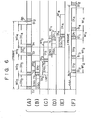
- the signal transmission times from central equipment 11 to the respective local equipments 12 1 to 12 4 are respectively 0.4A, 0.9A, 1.1 ⁇ and 2.3A.
- A stands for a proper clock time (for example, the time length of eight clock pulses).
- the time lengths TW' 1 to TW' 4 of data signals of the words allocated to local equipments 12 1 to 12 4 are set according to the subscriber data TWi .
- the timing of each word transmission is determined.
- the test signals are transmitted to the corresponding local equipments at the same timings as for corresponding words within one frame.
- the transmission timings of test signals addressed to local equipments. 12 2 , 12 3 , 12 1 , 12 4 are set to t l , t 2 , t 3 , t 4 , respectively, within one frame.
- the test signal consists of word sync signal SO i and test control signal DT t , as described before.
- the length of time of the test control signal is set to be considerably shorter than the length of time of the data signal of one word. Therefore, after a test signal is transmitted, the central equipment receives a responding signal to the transmitted test signal before the next test signal is transmitted.
- the test control signal DT t is formed of a bit stream of, for instance, "01111111".
- central equipment 11 receives, for instance, the word sync signal SI 2 as a responding signal to the test signal, transmitted at the time t 1 to local equipment 12 2 , after the time delay (0.9A x 2 + Ts) as shown in Fig. 4B; where Ts is the processing time in each local equipment from the reception of the test signal to the transmission of the responding signal.
- the central equipment measures the time delay (2TD i + Ts) for each local equipment and detects the maximum time delay (2TDmax + Ts).
- the maximum time delay is (4.6A + Ts) for the local equipment 12 4 .
- the transmission start times of local equipments 12 1 to 12 4 are controlled such that the time delays for the local equipments become all (2TDmax + Ts).
- the central equipment 11 calculates the difference DTi between the maximum time delay (2TDmax + Ts) and the time delay (2TD i + Ts) peculiar to each local equipment, depending on the position thereof, and sends DTi as control data to corresponding local equipment.
- the control data DT i is represented by "Oxxxxxxx”.
- the first bit “0" in the test control signal DT t and control data DT i is provided for distinguishing the succeeding bits from the normal data of a word.
- the seven bits represented by "x" ("1" or "0") of the control data represents an extra time delay to be added to the peculiar time delay of each local equipment. In this example, the extra time delays for the local equipments 12 1 to 12 4 are 3 .
- the control data DT i thus calculated is sent from transmitter 26 together with the corresponding word sync signal SOi at the same timing as the test signal, as shown in Fig. 5.
- Each local equipment controls the transmission start time according to the corresponding control data transmitted from central equipment 11. As a result, the difference between the transmission time of a word at the central equipment and the reception time of a corresponding responding word at the central equipment becomes same with respect to all the local equipments.
- responding words WI 3 , WI 1 and WI 4 appear on up link 14a with time delays of (1.1 ⁇ + 2.4 ⁇ + Ts), (0.4 ⁇ + 3.8A + Ts) and (2.3A + Ts), respectively, as shown in Figs. 6C, 6D and 6E.
- These responding words WI 2 , WI 3 , WI 1 , WI 4 on up link 14a arrive at receiver 21 in central equipment 11 with time delays of 0.9 ⁇ , 1.1 ⁇ , 0.4 ⁇ and 2.3A, respectively.
- a time space of about 0.1A may be provided between words transmitted from the local equipments.
- a space Sp is provided at the end of each frame to facilitate distinguishing between frames.
- the space Sp may be omitted, because frames can be distinguished by the previously known word sync signal of the first word in the frame.
- the maximum time delay (2TDmax + Ts) among the delay times associated with the local equipments is found, but the maximum time delay may be previously determined to be longer than (2TDmax + Ts).
- the circuit 28 includes control signal sending means 28 1 , delay time measuring means 28 2 and test signal/transmission-start time control-signal generating means 28 3 .
- the clock ⁇ 2 has, for example, about 10 times the frequency of clock ⁇ 1 .
- the control-signal sending means 28 1 has a shift register 41. In the test mode, subscriber data (word sync signal) SOi from subscriber data memory 27 and test control signal DTi from generating means 28 3 are loaded into shift register 41 at the transmission time of the word WOi to local equipment 12i.
- a counter 44 and a comparator 45 are provided for measuring the length of time of word WOi and triggering monostable multivibrator 43.
- the counter 44 counts clock pulses ⁇ 1 whose count value is compared, by comparator 45, with the subscriber data TW i from subscriber data memory 27.
- the subscriber data TW i represents the length of time of word WO i , which depends on the number and type of terminals 13 connected to local equipment 12i.
- the comparator 45 triggers monostable multivibrator 43 and clears counter 44.
- the monostable multivibrator 43 is arranged to, when triggered, provide a high level output during the period of time necessary for transmission of the test signal.
- the time delay measuring means 28 2 includes a counter 46 and a latch 47.
- the counter 46 counts clock pulses ⁇ 2 and is cleared by comparator 45.
- the count of counter 46 is latched in latch 47 in response to a detection signal (SIi) of word-sync signal-detecting circuits 2 for word sync signal SI i from local equipment 12 i . Since counter 46 is cleared at the same time that monostable multivibrator 43 is triggered by comparator 45, the count of counter 46, latched in latch 47, represents the time interval from the transmission of the test signal (SOi + DT t ) until the reception of the word sync signal SI i , i.e., the time delay (2TDi + Ts) associated with local equipment 12 i .
- the content of latch 47 representing the measured delay time is fed to a microcomputer 48, which constitutes control signal generating means 28 3 .
- the microcomputer 48 detects the maximum time delay (2TDmax + Ts) among the time delays measured for local equipments 12 1 to 12 4 and then calculates the control data DT i for each local equipment 12 i , as stated above.
- the calculated control data D Ti is loaded into shift register 41 together with the word sync signal SO i , as in the case of the test control signal DT t , and then sent out therefrom.
- shift register 41 At the beginning of the test mode and transmission-start timing-setting mode, shift register 41, monostable multivibrator 43, counters 44 and 46, and latch 47 are initialized by microcomputer 48.
- monostable multivibrator 43 When initialized, monostable multivibrator 43 provides a high level output for a predetermined period of time.
- the subscriber data SO i, TW i , test control signal DT t , and control data DT i are supplied to control signal sending means 28 1 at predetermined times (t l , t 2 , t 3 , t 4 ) under the control of microcomputer 48.
- the distributor 33 is arranged to receive only data "xxx...x” by making use of a bit "1" following the word sync signal. It includes a type-D flip-flop 51, which receives received data at its data input and is clocked by a word-sync signal-detection signal (SOi). When a word sync signal SOi is detected in the normal data transmission mode, the flip-flop 51 provides at its output the bit "1", following the word sync signal, to trigger monostable multivibrator 52.
- SOi word-sync signal-detection signal
- the multivibrator 52 When triggered, the multivibrator 52 is arranged to provide a high-level output to enable an AND gate 53 for a length of time of the word data part DOi.
- the word sync signal SO i when a word sync signal SO i is detected in the transmission mode, the following data "xxx...x” is supplied through AND gate 53 to distributing circuit 54.
- the bit following the word sync signal SOi is "0".
- the monostable multivibrator 52 is not triggered and the control signal is not supplied to distributing circuit 54.
- the comparators 57 compares an output signal of shift register 56 with.the test control signal "01111111” and control data "Oxxxxxx” to provide coincidence signals (DT t ) and (DTi).
- the coincidence signal (DT t ) which is obtained when the output signal of shift register 36 coincides with the test control signal DT t , triggers a monostable multivibrator 60 through an AND gate 59, which is enabled by monostable multivibrator 55.
- the output of multivibrator 60 goes high to enable an AND gate 61 for the length of time of the word sync signal SIi .
- clock pulses ⁇ 1 are supplied through AND gate 61 to a shift register 62.
- the shift register 62 receives the bits of the word sync signal SI i in parallel and sends out them serially in response to clock pulses ⁇ 1 .
- each local equipment 12i receives the test signal SOi + DT t , it sends out the word sync signal SI i as a responding signal to the central equipment 11.
- the comparators 57 When the output signal of shift register 56 coincides with the control data D T i "Oxxxxxxx" in the transmission-start timing-setting mode, the comparators 57 provides the coincidence signal (DTi), which is fed through an AND gate 63 to latch 58, whereby the output signal shift register 56 is latched in latch 58.
- the detection of the control data DTi in comparators 57 can be performed on the basis of a fact that the first bit of control data DT i is "0", and the remaining bits always include at least one bit "0".
- the control data DTi latched in latch 58 is fed to a comparator 64 in transmission-start timing-control circuit 38.
- the circuit 38 also includes a counter 65, which counts clock pulses ⁇ 2 and is cleared by the word-sync signal-detection signal (SIi).
- SIi word-sync signal-detection signal
- the comparator 64 compares the count of counter 65 with control data DTi. When a coincidence occurs, the comparator -64 produces an output signal to actuate multiplexer 35. As a result, the transmission of signal is started.
- the signal transmission is started after the time represented by the control data DTi latched in latch 58 in the transmission-start timing-setting mode has been passed from a point of time at which the word sync signal SO i is detected.
- the central equipment checks whether there is any collision or overspace between words transmitted from local equipments and adds corresponding control signals to words to be sent to the local equipments.
- the signal transmission timing is controlled such that neither collision nor overspace occurs between words from local equipments.
- Fig. 9 shows an arrangement of the central equipment in this embodiment. Like parts, as in the central equipment in the preceding embodiment shown in Fig. 2, are designated by the same reference numerals with a suffix a.
- Signals transmitted over up link 14a by local equipment 12 1 to 12 4 are applied to a receiver 21a, a collision detecting circuit 71, and an overspace detecting circuit 72.
- the collision detecting circuit 71 detects collisions between words from local equipments 12 1 to 12 4 according to a change in the level of a signal transmitted over up link 14a, which results from a collision as will be described later.
- the circuit 71 is arranged to, when detecting a collision, produce an output of "1".
- the overspace detecting circuit 72 detects an overspace between words from local equipments, and produces an output of "1" upon detection of an overspace.
- the collision-detection signal CD of circuit 71 and overspace-detection signal OSD of circuit 72 are applied to a.
- control-signal generating circuit 73 together with a word sync signal detecting signal (SIi) of word-sync signal-detecting circuit 22a.
- the control signal generating circuit 73 produces a control signal CTi which is applied to a multiplexer 25a.
- the control signal CTi is a 2-bit signal consisting of the collision detection signal CD and overspace detection signal OSD.
- the multiplexer 25a time-division multiplexes words addressed to local equipments.
- the words transmitted to local equipments each have a format as shown in Fig. 11, consisting of a word sync signal SO i stored in multiplexer 25a, a control signal CT i from control-signal generating circuit 73, and data signal DOi from exchange 24a.
- the time-division multiplexed words for the local equipments constitute one frame.
- the word sequence in the frame is predetermined. Therefore, it is possible for each local equipment to receive a self-addressed word by arranging a frame sync signal FSY at the head of the frame instead of adding a word sync signal to each word.
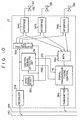
- Fig. 10 shows a structure of the local equipment.
- a control signal detecting circuit 74 is provided which is responsive to the detection of the word sync signal SOi by sync signal detecting circuit 32a to detect the control signal CTi succeeding to the sync signal.
- the detected control signal CTi is supplied to a transmission start-timing control circuit 75, which is connected between multiplexer 35a and transmitter 36a.
- the multiplexer 35a starts the time-division multiplexing of signals from terminals 13a to 13c to supply the signal to transmission start-time control circuit 75.
- the transmission start-time control circuit 75 controls the start-time of signal supply from multiplexer 35a to transmitter 36a in response to the detected control signal CTi.
- the control circuit 75 controls a delay time Ti from a point of time when the word sync signal is detected to a point of time when the word is actually transmitted from transmitter 36a over up link 14a.
- a common initial value of the delay time Ti is set.
- the control circuit 75 increases the delay time Ti to retard the transmission of a corresponding word.
- the control signal CTi is indicative of an overspace, it reduces the delay time T i to advance the transmission of the corresponding word.
- the delay time Ti is held at the initial value.
- the word sync signal of the preceeding word can be detected, while the word sync signal of the succeeding word cannot be detected.
- the control signal CTi indicative of a collision occurrence can be added to a word addressed to the local equipment, which transmitted the succeeding word in collision.
- the delay time Ti of the said local equipment increases.
- the signal transmitted over signal transmission path 14 may be encoded and modulated by various systems, and the method of collision detection varies with the adopted encoding and modulating systems.
- a collision detection method in case where a bi-phase encoding system is adopted will now be described with reference to Figs. 12 and 13.
- Fig. 12 shows the collision detecting circuit 71 and overspace detecting circuit 72.
- the collision detecting circuit 71 includes a lowpass filter (LPF) 81 connected to receive a signal transmitted over up link 14a, a comparator 82 for comparing an output voltage of lowpass filter 81 with a first threshold voltage SH 1 , and a monostable multivibrator 83 connected to the output of comparator 82.
- LPF lowpass filter
- SH 1 first threshold voltage
- monostable multivibrator 83 connected to the output of comparator 82.
- the comparator 82 produces an output of "1" to trigger monostable multivibrator 83, which thus produces a collision detection signal CD of a logic level "1" indicative of a collision.
- a comparator 84 compares the lowpass-filter output voltage with a second threshold voltage SH 2 to produce an output voltage of a logic level "1" while the lowpass-filter output voltage is lower than the voltage SH 2 .
- the comparator output is fed to a timer 85.
- the timer 85 measures the duration of the "1" level output voltage of comparator 84 to generate an output voltage corresponding to the duration. For example, this may be performed by counting clock pulses over the duration of the "1" level output voltage of comparator 84 and converting the count value into an analog voltage.
- the output voltage of timer 85 corresponds to a space between words, as will be described later in detail.
- a comparator 86 compares this voltage with a threshold voltage S m corresponding to the maximum permissible space. When the output voltage of timer 85 exceeds the voltage S m, the comparator 86 generates an output voltage of a logic level "1" to trigger a monostable multivibrator 87, which thus generates an overspace detection signal OSD of a logic level "I".
- Figs. 13D and 13E are simultaneously sent out over up link 14a. These signals are superimposed on each other, and the resultant composite signal, as shown in Fig. 13F, enters lowpass filter 81. Consequently, the lowpass filter 81 provides an output voltage, as shown in Fig. 13G, with the peak value thereof reaching as high as substantially double the level in the absence of a collision (Fig. 13C).
- the threshold voltage level S H 1 of comparator 82 of Fig. 12 is set to substantially 1.5 times the DC output voltage of lowpass filter 81 that is obtained in the absence of collision.
- the output of comparator 82 thus goes to a logic level "1", causing monostable multivibrator 83 to produce a collision-detection signal CD with a constant duration.
- the threshold voltage level SH2 of overspace detecting circuit 84 is set to substantially 0.5 D.
- the output voltage of lowpass filter 81 is zero volt.
- the output of comparator 84 goes high, representing the occurrence of a space.
- the timer 85 measures the duration of the space.
- the comparator 86 compares this duration with the maximum permissible duration of space.
- a monostable multivibrator 87 produces an overspace detection signal OSD having a fixed duration.
- the maximum permissible duration of space is desirably 1.2A.
- the transmission start time control is performed with a point of time of detection of a self-addressed word sync signal SO i by each local equipment taken as a reference time.
- the time interval from the reception of the self-addressed word to the detection of the.word sync signal SOi is set to T's for all the local equipments.
- the time Ti is a delay time which is controlled by transmission-start timing-control circuit 75.
- the words WO 1 to WO 4 transmitted from the central equipment 11 to the local equipments have an equal word length
- the words WI l to WI 4 transmitted from the local equipments to the central equipment have an equal word length.
- the first argorithm is as follows.
- the initial value of the controllable delay time Ti of each local equipment is assumed to be 5 ⁇ .
- the local equipments 12 3 , 12 1 , 12 4 and 12 2 transmit words WI 3 , WI 1 , WI 4 and WI 2 on up link 14a at timings as shown in Figs. 14B to 14E. These timings are each determined by the signal transmission time from the central equipment to each local equipment, time Ts required for the word sync signal detection, and delay time T i .
- Figs. 14A the words W0 3 , WO 1 , WO 4 and W0 2 are sequentially transmitted, as shown in Fig. 14A, on down link 14b
- the local equipments 12 3 , 12 1 , 12 4 and 12 2 transmit words WI 3 , WI 1 , WI 4 and WI 2 on up link 14a at timings as shown in Figs. 14B to 14E.
- These timings are each determined by the signal transmission time from the central equipment to each local equipment, time Ts required for the word sync signal detection, and delay
- time intervals T 3 , T1, T 4 and T 2 are equal to 5A, which is the initial value of the delay time Ti.
- the word transmitted from each local equipment on up link 14a reaches central equipment 11 after the lapse of the corresponding signal-transmission time.
- Fig. 14F shows the timings at which the words WI 3 , WI 1 , WI4 and WI2 arrive at central equipment 11. It will be seen that collisions Ql and Q2, shown as shadded, and overspaces Sl and S2 occur so long as the delay time T i is held at the initial value.
- the inter-word time Sij represents the time interval between two consequtive words WIi and WIj. It is indicative of a collision when it is negative, while it is indicative of an overspace when it is positive.
- the collisions Ql and Q2 are detected by collision detecting circuit 71, while the overspaces S l and S2 are detected by overspace detecting circuit 72.
- the word sync signals SI 3 and SI 4 of words WI 3 and WI 4 are detected by word-sync signal-detecting circuit 22a.
- the word sync signals SI 1 and SI 2 of words WI 1 and WI 2 cannot be detected due to collisions Q1 and Q2.
- the control-signal generating circuit 73 decides that a collision occurs between words WI 3 and WI 1 due to word WI 1 , and generates control signal CT 1 .
- the control signal CT 1 is expressed as "+".
- the control-signal generating circuit 73 also generates a control signal CT 2 (+) indicative of a collision.
- control signal generating circuit 73 For the overspace Sl between words WI 1 and WI 4 , the control signal generating circuit 73 generates a control signal CT 4 for word WI 4 .
- This control signal CT 4 is expressed as "-", indicating that the overspace detection signal OSD is "1".
- the overspace S2 is detected between the last word WT 2 in a frame and the first word WI 3 in the next frame.
- the control signal C T3 is not generated with respect to word WI 3 . This is because, according to the first control argorithm, the transmission start timing of the first word in the frame is not controlled.
- CT 3 is represented by "0".
- the control signal CTi generated in the manner as described, is added to the corresponding word WOi and then sent to the corresponding local equipment 12i.
- the control-signal detecting circuit 74 detects the control signal CTi which has two bits of a collision detection signal CD and overspace detection signal OSD.
- the transmission start-timing control circuit 75 increases the delay time T i by one unit time A to retard the transmission of word WIi.
- the overspace detection signal OSD is "1" (control signal CTi is represented by "-"), it reduces the delay time T i by ⁇ to advance the start of transmission of word WI i .
- both the detection signals CD and OSD are "0" (control signal CTi is represented as "0"), the delay time Ti remains unchanged.
- an inter-word time of zero is regarded as the occurrence of a collision (see Fig. 14J).
- the collision detecting circuit 71 may be modified to produce a collision detection signal of "1" when the output voltage of lowpass filter 81 is above a predetermined level over a length of time longer than a predetermined word length.
- the minimum value of space Sp between the last word WO 2 in a frame and the first word W0 3 in the next frame, as shown in Fig. 14A, is determined by an allowable space between words transmitted from local equipments 12 1 to 12 4 to central equipment 11.
- the control signal generating circuit 73 will now be described with reference to Fig. 15.
- the word number information i.e. addrerss information
- the word number information temporarily stored in memory 91 is applied to a decoder 92.
- the decoder 92 has output terminals 93 1 to 93 4 equal in number to the words in one frame.
- the decoder is arranged to decode the word number information of word WIi and generate a signal of "1" at an output corresponding to a word WIj to be transmitted next to the word WI i .
- the decoder 92 generates a signal of "1" at the output terminal 93 1 corresponding to the next word WI 1 .
- 2-bit shift registers 94 1 to 94 4 are provided for the respective outputs 93 1 to 93 4 of decoder 92.
- the first output 93 1 of decoder 92 and the collision detection signal CD from collision detecting circuit 71 are ANDed by an AND gate 95 1 to set a first stage of shift register 94 1 .
- the first decoder output 93 1 and the overspace detection signal OSD are ANDed by an AND gate 96 1 to set a second stage of shift register 94 1 .
- the first bit Q of shift register 94 1 is set to "I".
- AND gates 95 2 to 95 4 and 96 2 to 96 4 are provided for the respective registers 94 2 to 94 4 .
- the shift registers 94 1 to 94 4 generate control signals CT 1 to CT 4 corresponding to the words WI 1 to WI 4 , respectively.
- a rewriting circuit 97 is provided for rewriting the content of memory 91 in response to the collision detection signal CD. It is arranged to, when a collision occurs between words WIi and WI j , rewrite the word number information of the word WIj stored in memory 91 to the word number information of word WI k next to word WI j . As a result, a correct control signal can be generated for the word WI k .
- control signal generating circuit 73 When collision Q1 occurs between words WI 3 and WI 1 , as shown in Fig. 14F, the first bit Q of shift register 94 1 is set, so that a control signal CT 1 of "10" is obtained from shift register 94. This signal "10” corresponds to a control signal "+” indicative of a collision, as shown in Table 1.
- the memory 91 is rewritten to store the word number information of the word WI 4 next to the word WI 1 .
- the second bit of shift register 94 4 is set so that a control signal CT 4 of "01" is obtained.
- This signal "01” corresponds to a signal "-", as shown in Table 1.
- the word sync signal of the word WI 4 can be detected, so that the word number information thereof is stored in memory 91.
- the first bit of shift register 94 2 is set so that a control signal CT 2 of "10" is generated, and the memory 91 is rewritten to store the word number information of the word WI 3 .
- the shift register 94 3 For the overspace S2 between the word WI 2 and the first word WI 3 in the next frame, the shift register 94 3 generates a control signal CT 3 of "01". This control signal CT 3 is changed from "01" to "00" by suitable means. This is done because, according to the argorithm mentioned earlier, the transmission start timing of the first word in the frame is not controlled. Alternatively, the shift register 94 3 for the first word may be arranged so that it cannot be set by suitable means.
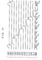
- Data signals DO 1 to D0 4 from exchange 24a are temporarily stored in memories 101 1 to 101 4 .
- Word sync signal generators 102 1 to 102 4 are provided for generating respective word sync signals SO 1 to S0 4 .
- the word sync signals SO l to S0 4 , control signals C T1 to CT 4 , and data DO 1 to DO 4 are applied to an AND-OR gate 103.
- a timing signal generating circuit 104 is provided which receives clock signal synchronized with exchange 24 and generates timing signals as shown in Figs. 17A to 17L, which are also fed to AND-OR gate 103.
- the AND-OR gate 103 generates one-frame transmission signal, as shown in Fig. 17M.
- the transmission-start timing-control circuit 75 will now be described with reference to Fig. 18. It includes an up/down counter 106, shift registers 107 1 to 107 4 , AND-OR gates 108 1 to 108 4 , and inverters 109 1 to 109 4 .
- the shift registers 107 1 to 107 4 have one, tow, four and eight stages, respectively, and thus provide delay times 1A, 2A, 4A and 8 ⁇ to the respective input signals thereof.
- the output of AND-OR gate 108 1 is coupled to transmitter 36a.
- the outputs of AND-OR gates 108 2 to 108 4 are coupled to the respective inputs of registers 107 1 to 107 3 .
- the output of multiplexer 35a is coupled to the input of shift register 107 4 .
- the input and output of shift register 107 1 are coupled to two inputs of AND-OR gate 108 1 .
- the input and output of shift registers 107 2 to 107 4 are coupled to two inputs of respective AND-OR gates 108 2 to 108 4 .
- the collision detection signal CD is applied to an up input of up/down counter 106, while the overspace detection signal OSD is applied to its down input.
- the up/down counter 106 provides four outputs Q 1 , Q 2 , Q 4 and Q 8 with respective weights of 1, 2, 4 and 8.
- the initial count of up/down counter 106 is set to 5, which corresponds to the initial value 5 ⁇ of the delay time T i described above.
- the outputs Q 1 , Q 2 , Q 4 and Q 8 of up/down counter 106 are coupled to AND-OR gates 108 1 to 108 4 as shown.
- the control circuit 75 when the count of up/down counter 106 is 5, the input signal from multiplexer 35a is applied to transmitter 36a through shift registers 107 3 and 107 1 . That is, a delay time of 5A is provided for the input signal. Every time a collision detection signal CD is supplied, the up/down counter 106 increments, so that the delay time Ti provided for an input signal increases by 1A. On the other hand, every time an overspace detection signal OSD is supplied, the up/down counter 106 decrements, thus reducing the delay time Ti by 1A.
- timing-control argorithms are given below.
- a second argorithm is as follows.
- a third argorithm is as follows.
- the central equipment detects a collision and an overspace between words and notifies each local equipment 12i of the direction of change of the daley time T i for the word WI i according to the result of detection. Whenever a collision or overspace is detected, the delay time T i is changed by a unit time.
- the central equipment may be arranged to measure the duration of a collision or overspace between words and correspondingly form a timing control signal of a plurality of bits representing the magnitude and direction of change of the delay time, so that the control of the delay time for each word is performed more rapidly than in the previous embodiment.
- a collision or overspace between words alone may be detected and the delay time Ti for the word WIi may be correspondingly controlled, to permit prevention of the collision and overspace.
Landscapes
- Engineering & Computer Science (AREA)
- Computer Networks & Wireless Communication (AREA)
- Theoretical Computer Science (AREA)
- Signal Processing (AREA)
- Physics & Mathematics (AREA)
- General Engineering & Computer Science (AREA)
- General Physics & Mathematics (AREA)
- Time-Division Multiplex Systems (AREA)
- Small-Scale Networks (AREA)
Applications Claiming Priority (4)
| Application Number | Priority Date | Filing Date | Title |
|---|---|---|---|
| JP53764/83 | 1983-03-31 | ||
| JP5376483A JPS59191993A (ja) | 1983-03-31 | 1983-03-31 | 集線分配方式 |
| JP53763/83 | 1983-03-31 | ||
| JP5376383A JPS59181796A (ja) | 1983-03-31 | 1983-03-31 | 集線分配方式 |
Publications (2)
| Publication Number | Publication Date |
|---|---|
| EP0121410A1 true EP0121410A1 (de) | 1984-10-10 |
| EP0121410B1 EP0121410B1 (de) | 1987-06-10 |
Family
ID=26394471
Family Applications (1)
| Application Number | Title | Priority Date | Filing Date |
|---|---|---|---|
| EP84302121A Expired EP0121410B1 (de) | 1983-03-31 | 1984-03-28 | Busartiges Lokalnetz mit Datenvermittlungsfähigkeit |
Country Status (4)
| Country | Link |
|---|---|
| US (1) | US4594705A (de) |
| EP (1) | EP0121410B1 (de) |
| CA (1) | CA1222035A (de) |
| DE (1) | DE3464185D1 (de) |
Cited By (6)
| Publication number | Priority date | Publication date | Assignee | Title |
|---|---|---|---|---|
| EP0186229A1 (de) * | 1984-12-15 | 1986-07-02 | Philips Patentverwaltung GmbH | Verfahren und Schaltungsanordnung zur Verkleinerung der Schutzzeiten zwischen Zeitkanälen eines digitalen Funkübertragungssystems |
| EP0188117A1 (de) * | 1984-12-20 | 1986-07-23 | Kabushiki Kaisha Toshiba | System zur Einstellung der Signalübertragungszeit in Zeit-Multiplex-Signalübertragung |
| EP0208021A2 (de) * | 1985-07-02 | 1987-01-14 | ANT Nachrichtentechnik GmbH | TDMA-Punkt- zu Mehrpunkt-Kommunikationssystem |
| EP0236876A2 (de) * | 1986-03-07 | 1987-09-16 | International Business Machines Corporation | Apparatur und Methode für Hochfrequenzsignalmessungen |
| EP0242142A2 (de) * | 1986-04-14 | 1987-10-21 | Kabushiki Kaisha Toshiba | System zum Zeitsteuerungsabgleich der Signalübertragung zur Vermeidung von Kollisionen |
| EP0357038A2 (de) * | 1988-08-31 | 1990-03-07 | Toshiba Lighting & Technology Corporation | Vorrichtung und Verfahren zur Signalübertragung, wobei die Antwortzeit verkürzt worden kann |
Families Citing this family (18)
| Publication number | Priority date | Publication date | Assignee | Title |
|---|---|---|---|---|
| JPS61161842A (ja) * | 1985-01-11 | 1986-07-22 | Sharp Corp | 信号送出方式 |
| US4799218A (en) * | 1985-03-28 | 1989-01-17 | Nissan Motor Company, Limited | Network system |
| US4740957A (en) * | 1985-07-26 | 1988-04-26 | American Telephone And Telegraph Company | Asynchronous addressable electronic key telephone system |
| JPH0761183B2 (ja) * | 1986-01-09 | 1995-06-28 | 株式会社東芝 | 集線分配装置 |
| US4739205A (en) * | 1986-02-24 | 1988-04-19 | Rockwell International Corporation | Telephone signal multiplexing system |
| JPH07123314B2 (ja) * | 1986-05-09 | 1995-12-25 | 日本電気株式会社 | 無線通信装置 |
| CA1280216C (en) * | 1986-08-05 | 1991-02-12 | At&T Global Information Solutions Company | Time slot protocol in the transmission of data in a data processing network |
| US4800558A (en) * | 1987-03-03 | 1989-01-24 | Pathfinder Systems, Inc. | Telephone switching system frame sync generator |
| US4890102A (en) * | 1987-05-26 | 1989-12-26 | Cabletron, Inc. | Visual display for communication network monitoring and troubleshooting |
| DE68919674T2 (de) * | 1989-02-08 | 1995-04-06 | Hewlett Packard Co | Verfahren und Gerät zur Diagnose von Netzwerken. |
| US5276678A (en) * | 1990-06-18 | 1994-01-04 | Intelect, Inc. | Distributed switching and telephone conferencing system |
| FR2725093B1 (fr) * | 1994-09-23 | 1996-12-27 | Cit Alcatel | Reseau de transmission point a multipoint a acces multiples par repartition temporelle |
| US5692126A (en) * | 1995-01-24 | 1997-11-25 | Bell Atlantic Network Services, Inc. | ISDN access to fast packet data network |
| DE19504488C1 (de) * | 1995-02-10 | 1996-06-20 | Siemens Ag | Verfahren zur Initialisierung von peripheren Einrichtungen durch eine programmgesteuerte Zentraleinrichttung eines Kommunikationssystems |
| US5867484A (en) * | 1997-01-31 | 1999-02-02 | Intellect Network Technologies | Switchable multi-drop video distribution system |
| US6195712B1 (en) * | 1997-06-13 | 2001-02-27 | Intel Corporation | Dynamic discovery of wireless peripherals |
| DE10048335A1 (de) * | 2000-09-29 | 2002-04-25 | Siemens Ag | Verfahren zur Messung von Verzögerungszeiten zwischen einem Taktgeber und einem Kommunikationsteilnehmer in einem Kommunikationsnetzwerk mit Verkettungstopologie, darauf aufbauende Verzögerungszeitkompensation sowie korrespondierendes Kommunikationsnetzwerk |
| CN103392311B (zh) * | 2011-02-25 | 2015-12-16 | 三菱电机株式会社 | 主控装置、从属装置以及时刻同步方法 |
Citations (6)
| Publication number | Priority date | Publication date | Assignee | Title |
|---|---|---|---|---|
| US3851104A (en) * | 1973-04-11 | 1974-11-26 | Mitre Corp | Digital communications system |
| EP0003849A2 (de) * | 1978-02-27 | 1979-09-05 | The Mitre Corporation | Digitales Buskommunikationssystem |
| EP0005045A1 (de) * | 1978-04-20 | 1979-10-31 | Network Systems Corporation | Impulsdatenkommunikationssystem und Adapter |
| US4229792A (en) * | 1979-04-09 | 1980-10-21 | Honeywell Inc. | Bus allocation synchronization system |
| FR2526249A1 (fr) * | 1982-04-30 | 1983-11-04 | Labo Electronique Physique | Procede et dispositif de calage temporel automatique de stations dans un multiplex temporel pour bus optique et systeme de transmission et de traitement de donnees comprenant un tel dispositif |
| FR2526250A1 (fr) * | 1982-04-30 | 1983-11-04 | Labo Electronique Physique | Procede de calage temporel automatique de stations dans un systeme de transmission par multiplex et de traitement de donnees |
Family Cites Families (7)
| Publication number | Priority date | Publication date | Assignee | Title |
|---|---|---|---|---|
| NO123200B (de) * | 1967-11-23 | 1971-10-11 | Svenska Handelsbanken | |
| US3984642A (en) * | 1974-06-10 | 1976-10-05 | The Post Office | Digital telephone and switching system employing time division multiplex pulse code modulation |
| US4078228A (en) * | 1975-03-24 | 1978-03-07 | Ohkura Electric Co., Ltd. | Loop data highway communication system |
| CA1086397A (en) * | 1976-09-14 | 1980-09-23 | Charles G. Diefenderfer | Polling an data communication system having a pulse position to binary address conversion circuit |
| US4161634A (en) * | 1978-07-31 | 1979-07-17 | Bell Telephone Laboratories, Incorporated | Count-down addressing system |
| US4271505A (en) * | 1979-07-02 | 1981-06-02 | The Foxboro Company | Process communication link |
| US4445214A (en) * | 1980-05-30 | 1984-04-24 | Harris Corporation | Method of controlling message transmission sequence in multi station communication system |
-
1984
- 1984-03-28 DE DE8484302121T patent/DE3464185D1/de not_active Expired
- 1984-03-28 EP EP84302121A patent/EP0121410B1/de not_active Expired
- 1984-03-29 US US06/594,896 patent/US4594705A/en not_active Expired - Lifetime
- 1984-03-30 CA CA000451009A patent/CA1222035A/en not_active Expired
Patent Citations (6)
| Publication number | Priority date | Publication date | Assignee | Title |
|---|---|---|---|---|
| US3851104A (en) * | 1973-04-11 | 1974-11-26 | Mitre Corp | Digital communications system |
| EP0003849A2 (de) * | 1978-02-27 | 1979-09-05 | The Mitre Corporation | Digitales Buskommunikationssystem |
| EP0005045A1 (de) * | 1978-04-20 | 1979-10-31 | Network Systems Corporation | Impulsdatenkommunikationssystem und Adapter |
| US4229792A (en) * | 1979-04-09 | 1980-10-21 | Honeywell Inc. | Bus allocation synchronization system |
| FR2526249A1 (fr) * | 1982-04-30 | 1983-11-04 | Labo Electronique Physique | Procede et dispositif de calage temporel automatique de stations dans un multiplex temporel pour bus optique et systeme de transmission et de traitement de donnees comprenant un tel dispositif |
| FR2526250A1 (fr) * | 1982-04-30 | 1983-11-04 | Labo Electronique Physique | Procede de calage temporel automatique de stations dans un systeme de transmission par multiplex et de traitement de donnees |
Non-Patent Citations (2)
| Title |
|---|
| DIGEST OF PAPERS COMPCON 82, 24th IEEE COMPUTER SOCIETY INTERNATIONAL CONFERENCE, 22nd-25th February 1982, San Francisco, pages 182-186, IEEE, New York, US; I. KONG et al.: "CableNet: a local area network reservation scheme" * |
| IEEE ELECTRO, vol. 7, May 1982, pages 1-7, New York, US; I. KONG: "Local area network - a broadband implementation" * |
Cited By (11)
| Publication number | Priority date | Publication date | Assignee | Title |
|---|---|---|---|---|
| EP0186229A1 (de) * | 1984-12-15 | 1986-07-02 | Philips Patentverwaltung GmbH | Verfahren und Schaltungsanordnung zur Verkleinerung der Schutzzeiten zwischen Zeitkanälen eines digitalen Funkübertragungssystems |
| EP0188117A1 (de) * | 1984-12-20 | 1986-07-23 | Kabushiki Kaisha Toshiba | System zur Einstellung der Signalübertragungszeit in Zeit-Multiplex-Signalübertragung |
| US4694453A (en) * | 1984-12-20 | 1987-09-15 | Kabushiki Kaisha Toshiba | System for adjusting signal transmission timing in time-division multiplexing signal transmission |
| EP0208021A2 (de) * | 1985-07-02 | 1987-01-14 | ANT Nachrichtentechnik GmbH | TDMA-Punkt- zu Mehrpunkt-Kommunikationssystem |
| EP0208021A3 (en) * | 1985-07-02 | 1988-07-06 | Ant Nachrichtentechnik Gmbh | Tdma point-to-multipoint communication system |
| EP0236876A2 (de) * | 1986-03-07 | 1987-09-16 | International Business Machines Corporation | Apparatur und Methode für Hochfrequenzsignalmessungen |
| EP0236876A3 (en) * | 1986-03-07 | 1989-02-22 | International Business Machines Corporation | Apparatus and method for high-frequency signal measuremeapparatus and method for high-frequency signal measurement nt |
| EP0242142A2 (de) * | 1986-04-14 | 1987-10-21 | Kabushiki Kaisha Toshiba | System zum Zeitsteuerungsabgleich der Signalübertragung zur Vermeidung von Kollisionen |
| EP0242142A3 (en) * | 1986-04-14 | 1989-08-23 | Kabushiki Kaisha Toshiba | System for adjusting signal transmission timing to prevent signal collisions |
| EP0357038A2 (de) * | 1988-08-31 | 1990-03-07 | Toshiba Lighting & Technology Corporation | Vorrichtung und Verfahren zur Signalübertragung, wobei die Antwortzeit verkürzt worden kann |
| EP0357038A3 (de) * | 1988-08-31 | 1992-05-27 | Toshiba Lighting & Technology Corporation | Vorrichtung und Verfahren zur Signalübertragung, wobei die Antwortzeit verkürzt worden kann |
Also Published As
| Publication number | Publication date |
|---|---|
| CA1222035A (en) | 1987-05-19 |
| EP0121410B1 (de) | 1987-06-10 |
| DE3464185D1 (en) | 1987-07-16 |
| US4594705A (en) | 1986-06-10 |
Similar Documents
| Publication | Publication Date | Title |
|---|---|---|
| EP0121410A1 (de) | Busartiges Lokalnetz mit Datenvermittlungsfähigkeit | |
| CA1172719A (en) | Distributed-structure message switching system on random-access channel for message dialogue among processing units | |
| US4757521A (en) | Synchronization method and apparatus for a telephone switching system | |
| US4502137A (en) | Digital signal transmitting method | |
| KR100365537B1 (ko) | 데이타 통신 방법 및 전자 기기 | |
| US4949336A (en) | Multi-slot access system | |
| US5309440A (en) | ISDN user-network interface system | |
| JP2723818B2 (ja) | バースト信号受信装置 | |
| EP0268664B1 (de) | Verfahren zum koppeln eines datensenders an eine signalleitung und vorrichtung zur durchführung des verfahrens | |
| US6510449B1 (en) | Data transmission system | |
| JP3088260B2 (ja) | 集積回路 | |
| US5136583A (en) | Data-communication method for loop-type network having portable slave stations connectable to addressable junction boxes permanently connected in the network | |
| US3851107A (en) | Fault detecting device for multiplex signal transmission system | |
| EP0059821A1 (de) | Verfahren und Vorrichtung, z.B. in einem Datenverteilungssystem, unter anderem zur Vermeidung von Verzerrungen bei der Übertragung von Signalzuständen | |
| JP2641487B2 (ja) | 複数の端末装置の同時作動装置 | |
| JPH0846632A (ja) | バス競合制御方式 | |
| SU868742A1 (ru) | Многоканальное устройство дл сопр жени каналов ввода-вывода с внешними устройствами | |
| JP3042084B2 (ja) | インタフェース回路 | |
| JPS59188257A (ja) | 信号伝送方式 | |
| JPH0522289A (ja) | 同報通信制御方式 | |
| JPS62222798A (ja) | 時分割多重信号伝送方式 | |
| JPH0262080B2 (de) | ||
| JPH039666B2 (de) | ||
| JPH04290026A (ja) | タイミング再生方式 | |
| JPS58173938A (ja) | 複数ビツト単位のデ−タ伝送制御方法 |
Legal Events
| Date | Code | Title | Description |
|---|---|---|---|
| PUAI | Public reference made under article 153(3) epc to a published international application that has entered the european phase |
Free format text: ORIGINAL CODE: 0009012 |
|
| 17P | Request for examination filed |
Effective date: 19840419 |
|
| AK | Designated contracting states |
Designated state(s): DE FR GB |
|
| GRAA | (expected) grant |
Free format text: ORIGINAL CODE: 0009210 |
|
| AK | Designated contracting states |
Kind code of ref document: B1 Designated state(s): DE FR GB |
|
| REF | Corresponds to: |
Ref document number: 3464185 Country of ref document: DE Date of ref document: 19870716 |
|
| ET | Fr: translation filed | ||
| PLBE | No opposition filed within time limit |
Free format text: ORIGINAL CODE: 0009261 |
|
| STAA | Information on the status of an ep patent application or granted ep patent |
Free format text: STATUS: NO OPPOSITION FILED WITHIN TIME LIMIT |
|
| 26N | No opposition filed | ||
| REG | Reference to a national code |
Ref country code: GB Ref legal event code: 746 Effective date: 19981008 |
|
| REG | Reference to a national code |
Ref country code: FR Ref legal event code: D6 |
|
| REG | Reference to a national code |
Ref country code: GB Ref legal event code: IF02 |
|
| PGFP | Annual fee paid to national office [announced via postgrant information from national office to epo] |
Ref country code: FR Payment date: 20030310 Year of fee payment: 20 |
|
| PGFP | Annual fee paid to national office [announced via postgrant information from national office to epo] |
Ref country code: GB Payment date: 20030326 Year of fee payment: 20 |
|
| PGFP | Annual fee paid to national office [announced via postgrant information from national office to epo] |
Ref country code: DE Payment date: 20030409 Year of fee payment: 20 |
|
| PG25 | Lapsed in a contracting state [announced via postgrant information from national office to epo] |
Ref country code: GB Free format text: LAPSE BECAUSE OF EXPIRATION OF PROTECTION Effective date: 20040327 |
|
| REG | Reference to a national code |
Ref country code: GB Ref legal event code: PE20 |