EP0236876A2 - Apparatur und Methode für Hochfrequenzsignalmessungen - Google Patents
Apparatur und Methode für Hochfrequenzsignalmessungen Download PDFInfo
- Publication number
- EP0236876A2 EP0236876A2 EP87102785A EP87102785A EP0236876A2 EP 0236876 A2 EP0236876 A2 EP 0236876A2 EP 87102785 A EP87102785 A EP 87102785A EP 87102785 A EP87102785 A EP 87102785A EP 0236876 A2 EP0236876 A2 EP 0236876A2
- Authority
- EP
- European Patent Office
- Prior art keywords
- transmission line
- signals
- time
- signal
- propagation delay
- Prior art date
- Legal status (The legal status is an assumption and is not a legal conclusion. Google has not performed a legal analysis and makes no representation as to the accuracy of the status listed.)
- Granted
Links
- 238000005259 measurement Methods 0.000 title claims abstract description 29
- 238000000034 method Methods 0.000 title claims abstract description 5
- 230000005540 biological transmission Effects 0.000 claims abstract description 83
- 230000001934 delay Effects 0.000 description 3
- 238000002310 reflectometry Methods 0.000 description 3
- 230000009977 dual effect Effects 0.000 description 2
- 230000000694 effects Effects 0.000 description 2
- 239000004698 Polyethylene Substances 0.000 description 1
- 239000004809 Teflon Substances 0.000 description 1
- 229920006362 Teflon® Polymers 0.000 description 1
- 238000010521 absorption reaction Methods 0.000 description 1
- 230000003321 amplification Effects 0.000 description 1
- 239000003989 dielectric material Substances 0.000 description 1
- 230000002500 effect on skin Effects 0.000 description 1
- 238000003199 nucleic acid amplification method Methods 0.000 description 1
- -1 polyethylene Polymers 0.000 description 1
- 229920000573 polyethylene Polymers 0.000 description 1
Images

Classifications
-
- G—PHYSICS
- G01—MEASURING; TESTING
- G01R—MEASURING ELECTRIC VARIABLES; MEASURING MAGNETIC VARIABLES
- G01R27/00—Arrangements for measuring resistance, reactance, impedance, or electric characteristics derived therefrom
- G01R27/28—Measuring attenuation, gain, phase shift or derived characteristics of electric four pole networks, i.e. two-port networks; Measuring transient response
Definitions
- This invention relates to the measurement of signal sources and in particular to an apparatus and a method for measuring the time relationship of two signals from different signal sources coupled into different points on a transmission line without knowing the physical distance between the signal source and the measurement device or the propagation delays of the transmission line.
- Prior art measuring devices primarily consisted of apparatus for measuring unknown network parameters or transmission media discontinuities using a known signal source.
- time domain reflectometry devices In such apparatus the measurement of unknown signal sources is affected by the transmission line or network through which it is passing and the distance between the signal source and the transmission line as well as the distance between the measuring device and the transmission line.
- General reflectometry measurement type devices are shown in US-A-4,230,982 and US-A-4,440,985. None of these prior art devices can measure the relationship of two signals applied at different points on a transmission line without knowing the propagation delays of the line.
- the present invention solves this problem and proposes an apparatus for and a method of measuring the time coherence of high frequency signals fed into different points along a high frequency transmission line regardless of where the input signal enters the line or what the propagation delay of the line is.
- any transmission medium positioned between the signal source and the measurement device becomes effectively transparent. This means that minimal signal loss and no phase change or propagation delay change due to physical position is realized. Thus, significant advantages are realized from the present invention.
- the apparatus of the present invention basically comprises a plurality of voltage sensors, having signal source inputs, mounted on a transmission line terminated at both ends. To each end of the line there is coupled a measurement device to permit signal measurement at both ends of the transmission line.
- a measurement device to permit signal measurement at both ends of the transmission line.
- the high frequency signals from the sensors are permitted to feed into the transmission line.
- These high frequency signals upon entering the transmission line, via the sensors propagate in both directions at an equal speed until they reach each end of the line where their time relationships are measured. Because the line is terminated at both ends by selected impedances, reflections do not occur.
- the time average of these measurements is independent of the transmission line propagation delay or the sensor positions on the transmission line and provides the true, i.e. real, time relationship of the two signals fed into the transmission line, even though both signals are measured at the same remote points and even though the propagation delays of the line are unknown.
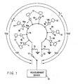
- a high-frequency transmission line 10 which is terminated at both end nodes 11 and 12 by impedances 13 and 14.
- This transmission line is a continuous signal path having a characteristic impedance and capacitance per unit length.
- An AC signal measuring device 15, such as an oscilloscope, is switchably coupled to each end node 11 and 12.
- Disposed along and coupled to the line is a plurality of input signal sensors 16 to which are coupled to high-frequency signal sources 17.
- Each sensor is controlled by an external logic signal introduced into the sensor through a node 18 from a suitable source, not shown.
- a discontinuity will result. This discontinuity will cause phase and voltage distortions of signals passing through the line.
- the lumped discontinuities become a distributed parameter medium which will pass signals with minimum distortion.
- each device exhibits a capacitance C
- the transmission line would appear to be continuous but have a characteristic impedance of: where: Z0 is the unloaded transmission line impedance; C0 is the total unloaded transmission line capacitance; N is the number of devices.
- the rise time (frequency and phase components) of the signal will not change because of the additional capacitance. This is identical to the effect observed in transmission lines constructed with different dielectric materials.
- a transmission line constructed with a teflon or polyethylene dielectric having a dielectric constant of 2,3 will propagate a signal 30% faster than a transmission line constructed with a G-10 dielectric, i.e., one having a dielectric constant of 4,7.
- the rise time of the signals at the end of either transmission line will be identical.
- the sensors 16 can each be any amplification or switching device, such as an active transistor which matches the impedance of the signal sources to the impedance of the transmission line 10. Generally, however, such sensors must be small enough to permit mounting in close proximity to one another along the line.
- the measuring device 15 utilized can be any high-frequency instrument which is capable of measuring the signals at both ends of the transmission line. It must not alter the impedance of the terminations. For example, in the actual embodiment, two relays, a dual pnp transistor and a conventional comparator provide these requirements.
- sensors 16 are equally spaced in close proximity to one another and have their outputs each connected to the same transmission line 10 as shown in Fig. 1.
- the output of any one sensor 16 may be switched onto, or disconnected from, the transmission line 10 by a logic signal 18.
- a measurement device 15, such as an oscilloscope comparator, is used to measure the signal at each end of the transmission line. The time average value of these measurements is then utilized to yield a measurement which is independent of transmission line propagation delay or sensor position on the line.
- the input signal from sensor 16a is connected to the transmission line 10 by logic signal on control line 18a.
- the time at which the signal T1 reaches node 11 is measured and recorded. This reading is displaced in time by the propagation delay TD1 of the transmission line 10.
- a similar reading is made at node 12.
- This reading is displaced in time by the propagation delay TD1′ of the line.
- the arithmetic mean of these readings yields:
- the sensor 16a is disconnected and a different sensor 16b is connected.
- the measurements at nodes 11 and 12 are repeated, that is, the time the signal T2 takes to travel from sensor 16b to node 11 through the line propagation delay TD2, and the time it takes the signal T2 to travel through the line propagation delay TD2′.
- the arithmetic mean of these readings yields:
- the difference in the two readings yields the phase or delay between the two signals.
- Fig. 2 shows, graphically, the true or real time relationship of the two input signals V1 and V2 whose time relationship TD R is to be measured.
- Fig. 3 shows the time relationship of input signals V1 and V2 as measured at node 11, and
- Fig. 4 shows the time relationship of V1 and V2 as measured at node 12. It should be noted that Figs. 2, 3 and 4 delineate the signals observed at nodes 11 and 12 on the circuit of Fig. 1, and that the time average of the propagation delay yields the desired result.
- transmission line 10 which appears as a continuous distributed-parameter signal path having the impedance of Z, and propagates in both directions at equal speed. Because transmission line 10 is terminated at both ends by the impedances Z, no reflections occur. The signal is observed at both terminations, and the arithmetic mean of time phase information is computed. This computation renders the measurements independent of the physical positions of the sensors on the line.
- Fig. 2 shows, graphically, the true or real time relationship TD R of two input signals V1 and V2 when these signals are supplied to transmission line 10 via sensors 16a and 16b respectively. It is this true time relationship which is to be determined.
- the measured time relationship of the signals V1 and V2 at this node 11 is equal to the true time relationship TD R between the signals plus the propagation delay of that portion of transmission line 10 between the sensors 16a and 16b, i.e. TD2 minus TD1.
- TD R true time relationship between the signals plus the propagation delay of that portion of transmission line 10 between the sensors 16a and 16b
- the measuring device 15 when the measuring device 15 is connected to the other end, node 12, of transmission line 10, the time relationship of the two signals V1 and V2 is again measured. At this end, the measured time relationship is equal to the true time relationship TD R minus the propagation delay TD2 - TD1 of that portion of the transmission line 10 between the sensors 16a and 16b. This measured relationship is shown in Fig. 4.
- the invention thus teaches an AC measurement apparatus which permits measurement of multiple unknown signal sources independent of the physical distance between the signal sources and the measurement device.
- the transmission line is effectively transparent to the measurement device, and the time relationship of the signals can be measured with substantially no loss and no phase change due either to physical position or to propagation delay change of the signal source on the line.
Landscapes
- Physics & Mathematics (AREA)
- General Physics & Mathematics (AREA)
- Measurement Of Resistance Or Impedance (AREA)
- Measurement Of Unknown Time Intervals (AREA)
Applications Claiming Priority (2)
| Application Number | Priority Date | Filing Date | Title |
|---|---|---|---|
| US06/837,117 US4720822A (en) | 1986-03-07 | 1986-03-07 | High frequency signal measurement method and apparatus |
| US837117 | 1986-03-07 |
Publications (3)
| Publication Number | Publication Date |
|---|---|
| EP0236876A2 true EP0236876A2 (de) | 1987-09-16 |
| EP0236876A3 EP0236876A3 (en) | 1989-02-22 |
| EP0236876B1 EP0236876B1 (de) | 1991-10-16 |
Family
ID=25273562
Family Applications (1)
| Application Number | Title | Priority Date | Filing Date |
|---|---|---|---|
| EP87102785A Expired - Lifetime EP0236876B1 (de) | 1986-03-07 | 1987-02-27 | Apparatur und Methode für Hochfrequenzsignalmessungen |
Country Status (4)
| Country | Link |
|---|---|
| US (1) | US4720822A (de) |
| EP (1) | EP0236876B1 (de) |
| JP (1) | JPS62207992A (de) |
| DE (1) | DE3773705D1 (de) |
Families Citing this family (5)
| Publication number | Priority date | Publication date | Assignee | Title |
|---|---|---|---|---|
| JPS63163296A (ja) * | 1986-12-26 | 1988-07-06 | Hitachi Ltd | 時間差測定回路 |
| CA2032342C (en) * | 1989-12-15 | 1993-10-26 | Toshihiko Nannichi | Picture digitizing system |
| JPH05336043A (ja) * | 1992-05-29 | 1993-12-17 | Sharp Corp | 光通信ユニット |
| WO2004021176A2 (de) | 2002-08-07 | 2004-03-11 | Pact Xpp Technologies Ag | Verfahren und vorrichtung zur datenverarbeitung |
| US7394284B2 (en) | 2002-09-06 | 2008-07-01 | Pact Xpp Technologies Ag | Reconfigurable sequencer structure |
Family Cites Families (4)
| Publication number | Priority date | Publication date | Assignee | Title |
|---|---|---|---|---|
| CH623963A5 (de) * | 1977-10-28 | 1981-06-30 | Bbc Brown Boveri & Cie | |
| DE2931101C2 (de) * | 1979-07-31 | 1985-04-18 | Siemens AG, 1000 Berlin und 8000 München | Verfahren zur Ermittlung der Übertragungseigenschaften von elektrischen Nachrichtenleitungen |
| US4440985A (en) * | 1981-06-22 | 1984-04-03 | Bell Telephone Laboratories, Incorporated | Apparatus for determining the location of faults in a transmission line |
| EP0121410B1 (de) * | 1983-03-31 | 1987-06-10 | Kabushiki Kaisha Toshiba | Busartiges Lokalnetz mit Datenvermittlungsfähigkeit |
-
1986
- 1986-03-07 US US06/837,117 patent/US4720822A/en not_active Expired - Lifetime
-
1987
- 1987-02-06 JP JP62024894A patent/JPS62207992A/ja active Granted
- 1987-02-27 EP EP87102785A patent/EP0236876B1/de not_active Expired - Lifetime
- 1987-02-27 DE DE8787102785T patent/DE3773705D1/de not_active Expired - Lifetime
Also Published As
| Publication number | Publication date |
|---|---|
| EP0236876B1 (de) | 1991-10-16 |
| JPS62207992A (ja) | 1987-09-12 |
| JPH0464597B2 (de) | 1992-10-15 |
| DE3773705D1 (de) | 1991-11-21 |
| US4720822A (en) | 1988-01-19 |
| EP0236876A3 (en) | 1989-02-22 |
Similar Documents
| Publication | Publication Date | Title |
|---|---|---|
| US4734637A (en) | Apparatus for measuring the length of an electrical line | |
| US4755742A (en) | Dual channel time domain reflectometer | |
| Catt | Crosstalk (noise) in digital systems | |
| US3703829A (en) | Liquid quantity gaging system | |
| US6822463B1 (en) | Active differential test probe with a transmission line input structure | |
| US5502392A (en) | Methods for the measurement of the frequency dependent complex propagation matrix, impedance matrix and admittance matrix of coupled transmission lines | |
| US4247817A (en) | Transmitting electrical signals with a transmission time independent of distance between transmitter and receiver | |
| US5003256A (en) | Clock skew measurement technique | |
| Tabbara | Reconstruction of permittivity profiles from a spectral analysis of the reflection coefficient | |
| Dascher | Measuring parasitic capacitance and inductance using TDR | |
| US5011262A (en) | Fiber optic sensor array | |
| US5235566A (en) | Clock skew measurement technique | |
| EP0236876B1 (de) | Apparatur und Methode für Hochfrequenzsignalmessungen | |
| CA2118148C (en) | Reflective wave compensation on high speed processor cards | |
| Agrawal et al. | Experimental characterization of multiconductor transmission lines in inhomogeneous media using time-domain techniques | |
| US3479587A (en) | Reflection-coefficient measuring apparatus | |
| RU2047869C1 (ru) | Способ определения места повреждения оптического кабеля с металлическими элементами | |
| Mao et al. | Synthesis of coupled transmission lines | |
| Richter | Calculation of Voltages and Currents on Lossy Multiconductor Transmission Line Systems in the Time Domain | |
| Wagenblaßt et al. | An Approach of Rule Development for Reflection and Crosstalk Effects on Printed Circuit Boards | |
| Gould | Transmission-line impedance measurement at microwave frequencies | |
| Dolocan | A new method for dielectric and ferroelectric characteristics measurements | |
| US4775244A (en) | Method and apparatus for measurement of pulse width of very short pulses | |
| Williams et al. | Technique for reducing digit noise in very fast magnetic-film stores | |
| Wheeler et al. | Transmission Line Time-Domain Analysis and Signal Integrity |
Legal Events
| Date | Code | Title | Description |
|---|---|---|---|
| PUAI | Public reference made under article 153(3) epc to a published international application that has entered the european phase |
Free format text: ORIGINAL CODE: 0009012 |
|
| AK | Designated contracting states |
Kind code of ref document: A2 Designated state(s): DE FR GB |
|
| 17P | Request for examination filed |
Effective date: 19880126 |
|
| PUAL | Search report despatched |
Free format text: ORIGINAL CODE: 0009013 |
|
| AK | Designated contracting states |
Kind code of ref document: A3 Designated state(s): DE FR GB |
|
| 17Q | First examination report despatched |
Effective date: 19910208 |
|
| GRAA | (expected) grant |
Free format text: ORIGINAL CODE: 0009210 |
|
| AK | Designated contracting states |
Kind code of ref document: B1 Designated state(s): DE FR GB |
|
| REF | Corresponds to: |
Ref document number: 3773705 Country of ref document: DE Date of ref document: 19911121 |
|
| ET | Fr: translation filed | ||
| PGFP | Annual fee paid to national office [announced via postgrant information from national office to epo] |
Ref country code: GB Payment date: 19920113 Year of fee payment: 6 |
|
| PGFP | Annual fee paid to national office [announced via postgrant information from national office to epo] |
Ref country code: FR Payment date: 19920124 Year of fee payment: 6 |
|
| PGFP | Annual fee paid to national office [announced via postgrant information from national office to epo] |
Ref country code: DE Payment date: 19920304 Year of fee payment: 6 |
|
| PLBE | No opposition filed within time limit |
Free format text: ORIGINAL CODE: 0009261 |
|
| STAA | Information on the status of an ep patent application or granted ep patent |
Free format text: STATUS: NO OPPOSITION FILED WITHIN TIME LIMIT |
|
| 26N | No opposition filed | ||
| PG25 | Lapsed in a contracting state [announced via postgrant information from national office to epo] |
Ref country code: GB Effective date: 19930227 |
|
| GBPC | Gb: european patent ceased through non-payment of renewal fee |
Effective date: 19930227 |
|
| PG25 | Lapsed in a contracting state [announced via postgrant information from national office to epo] |
Ref country code: FR Effective date: 19931029 |
|
| PG25 | Lapsed in a contracting state [announced via postgrant information from national office to epo] |
Ref country code: DE Effective date: 19931103 |
|
| REG | Reference to a national code |
Ref country code: FR Ref legal event code: ST |