EP0121189A1 - Circuit de contre-réaction pour la régulation de la tension de commandee en fonction de la température dans un tube á propagation d'ondes - Google Patents
Circuit de contre-réaction pour la régulation de la tension de commandee en fonction de la température dans un tube á propagation d'ondes Download PDFInfo
- Publication number
- EP0121189A1 EP0121189A1 EP84103197A EP84103197A EP0121189A1 EP 0121189 A1 EP0121189 A1 EP 0121189A1 EP 84103197 A EP84103197 A EP 84103197A EP 84103197 A EP84103197 A EP 84103197A EP 0121189 A1 EP0121189 A1 EP 0121189A1
- Authority
- EP
- European Patent Office
- Prior art keywords
- temperature
- traveling wave
- circuit arrangement
- wave tube
- tube
- Prior art date
- Legal status (The legal status is an assumption and is not a legal conclusion. Google has not performed a legal analysis and makes no representation as to the accuracy of the status listed.)
- Granted
Links
- 230000001105 regulatory effect Effects 0.000 title 1
- 230000001419 dependent effect Effects 0.000 claims abstract description 13
- 238000010438 heat treatment Methods 0.000 abstract description 2
Images

Classifications
-
- H—ELECTRICITY
- H03—ELECTRONIC CIRCUITRY
- H03F—AMPLIFIERS
- H03F1/00—Details of amplifiers with only discharge tubes, only semiconductor devices or only unspecified devices as amplifying elements
- H03F1/30—Modifications of amplifiers to reduce influence of variations of temperature or supply voltage or other physical parameters
-
- H—ELECTRICITY
- H01—ELECTRIC ELEMENTS
- H01J—ELECTRIC DISCHARGE TUBES OR DISCHARGE LAMPS
- H01J23/00—Details of transit-time tubes of the types covered by group H01J25/00
- H01J23/34—Circuit arrangements not adapted to a particular application of the tube and not otherwise provided for
Definitions
- the invention relates to a circuit arrangement for temperature-dependent cathode current tracking in traveling wave tubes.
- the object of the present invention is to achieve a temperature-dependent tracking of the control voltage in order to obtain a relatively constant cathode current by heating the tube.
- This object is achieved in that the circuit arrangement is thermally coupled at a suitable point with the traveling wave tube and consists of a temperature-dependent network which measures the current tube temperature and via control electronics in the power supply by voltage variation on a control electrode of the traveling wave tube, the preselected cathode current almost constant can hold.
- the circuit arrangement is preferably in the vicinity of the control electrodes determining the cathode current. attached and thermally sufficiently well coupled.
- the circuit arrangement according to the invention has the advantage that an integrated circuit, consisting of a temperature-dependent network, which is arranged at a suitable point on the tube, measures the current tube temperature and, via an electrically conductive connection, preferably tracks the G 2 voltage via a control input in the power supply unit such that a Almost constant cathode current flows over a wide temperature range and the output power accordingly remains constant.
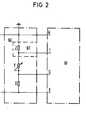
- the amplifier consists of the power supply unit N, the traveling wave tube W and the temperature-dependent network T, which measures the current tube temperature.
- the cathode current in the traveling wave tube W can be kept almost constant by varying the voltage on a control electrode, for example control electrode G.
- the traveling wave tube W essentially consists of the cathode K, the grid G, the filament H and the collectors C 1 and C 2.
- the power supply unit N is composed essentially of the collector voltage sources NC 1 and NC 2, the filament voltage source NH, the grid voltage source NG and the temperature tracking NT together.
- the HF inputs and outputs of the traveling wave tube W are indicated by arrows labeled HF-ON and HF-AUS.
- the circuit essentially consists of a high-voltage resistance divider X, Y and Z, the basic setting of the cathode current being made with the resistor Y.
- the temperature-dependent network T is connected in parallel with the resistor Z in such a way that the cross-current through the resistors X, Y and Z changes with the change in the resistance in the temperature-dependent network T and a voltage change at the resistor X related to the cathode K is associated therewith.
- the voltage across the resistor X influences the cathode current via the control input G of the traveling wave tube W.
- the grid voltage source is provided with the letters NG and the delay line, which is designed as a coil in this exemplary embodiment, is provided with the letter H.
Landscapes
- Engineering & Computer Science (AREA)
- Power Engineering (AREA)
- Microwave Tubes (AREA)
- Microwave Amplifiers (AREA)
- Amplifiers (AREA)
Applications Claiming Priority (2)
| Application Number | Priority Date | Filing Date | Title |
|---|---|---|---|
| DE3311674 | 1983-03-30 | ||
| DE19833311674 DE3311674A1 (de) | 1983-03-30 | 1983-03-30 | Schaltungsanordnung zur temperaturabhaengigen kathodenstromnachfuehrung in wanderfeldroehren |
Publications (2)
| Publication Number | Publication Date |
|---|---|
| EP0121189A1 true EP0121189A1 (fr) | 1984-10-10 |
| EP0121189B1 EP0121189B1 (fr) | 1987-06-24 |
Family
ID=6195144
Family Applications (1)
| Application Number | Title | Priority Date | Filing Date |
|---|---|---|---|
| EP84103197A Expired EP0121189B1 (fr) | 1983-03-30 | 1984-03-22 | Circuit de contre-réaction pour la régulation de la tension de commandee en fonction de la température dans un tube á propagation d'ondes |
Country Status (5)
| Country | Link |
|---|---|
| US (1) | US4638215A (fr) |
| EP (1) | EP0121189B1 (fr) |
| JP (1) | JPS59184438A (fr) |
| CA (1) | CA1226909A (fr) |
| DE (2) | DE3311674A1 (fr) |
Families Citing this family (6)
| Publication number | Priority date | Publication date | Assignee | Title |
|---|---|---|---|---|
| JPH07101596B2 (ja) * | 1992-12-09 | 1995-11-01 | 株式会社宇宙通信基礎技術研究所 | 進行波管増幅器 |
| DE19710100A1 (de) * | 1997-03-12 | 1998-09-17 | Bosch Gmbh Robert | Anordnung insbesondere für die Ansteuerung einer Wanderfeldröhre |
| US7002301B2 (en) * | 2003-10-15 | 2006-02-21 | Lutron Electronics Co., Inc. | Apparatus and methods for making capacitive measurements of cathode fall in fluorescent lamps |
| US7116055B2 (en) * | 2003-10-15 | 2006-10-03 | Lutron Electronics Co., Inc. | Apparatus and methods for making spectroscopic measurements of cathode fall in fluorescent lamps |
| EP2296165A1 (fr) * | 2009-09-14 | 2011-03-16 | L-3 Communications Corporation | Canon à électrons commuté à élément double |
| US8492978B2 (en) * | 2009-09-14 | 2013-07-23 | L-3 Communications Corporation | Dual element switched electron gun |
Citations (5)
| Publication number | Priority date | Publication date | Assignee | Title |
|---|---|---|---|---|
| US3254265A (en) * | 1961-02-24 | 1966-05-31 | Varian Associates | Means for controlling frequency of an electron tube |
| US3267322A (en) * | 1961-02-23 | 1966-08-16 | Varian Associates | Frequency stable temperature compensated electron tube |
| US3316485A (en) * | 1962-10-08 | 1967-04-25 | Varian Associates | Beam current measurement by inductive techniques for high frequency electron discharge devices |
| FR2401510A1 (fr) * | 1977-04-29 | 1979-03-23 | Thomson Csf | Tube electronique a interaction d'un faisceau avec une onde, et notamment tube a onde progressive, a intensite de faisceau stabilisee |
| EP0037385A2 (fr) * | 1980-04-02 | 1981-10-07 | Telefonaktiebolaget L M Ericsson | Dispositif pour limiter l'accroissement du courant cathodique dû à la variation de la distance cathode-grille, pendant la phase initiale, d'un tube à ondes progressives |
-
1983
- 1983-03-30 DE DE19833311674 patent/DE3311674A1/de not_active Withdrawn
-
1984
- 1984-03-22 DE DE8484103197T patent/DE3464436D1/de not_active Expired
- 1984-03-22 EP EP84103197A patent/EP0121189B1/fr not_active Expired
- 1984-03-27 US US06/593,953 patent/US4638215A/en not_active Expired - Fee Related
- 1984-03-28 CA CA000450704A patent/CA1226909A/fr not_active Expired
- 1984-03-30 JP JP59063130A patent/JPS59184438A/ja active Pending
Patent Citations (5)
| Publication number | Priority date | Publication date | Assignee | Title |
|---|---|---|---|---|
| US3267322A (en) * | 1961-02-23 | 1966-08-16 | Varian Associates | Frequency stable temperature compensated electron tube |
| US3254265A (en) * | 1961-02-24 | 1966-05-31 | Varian Associates | Means for controlling frequency of an electron tube |
| US3316485A (en) * | 1962-10-08 | 1967-04-25 | Varian Associates | Beam current measurement by inductive techniques for high frequency electron discharge devices |
| FR2401510A1 (fr) * | 1977-04-29 | 1979-03-23 | Thomson Csf | Tube electronique a interaction d'un faisceau avec une onde, et notamment tube a onde progressive, a intensite de faisceau stabilisee |
| EP0037385A2 (fr) * | 1980-04-02 | 1981-10-07 | Telefonaktiebolaget L M Ericsson | Dispositif pour limiter l'accroissement du courant cathodique dû à la variation de la distance cathode-grille, pendant la phase initiale, d'un tube à ondes progressives |
Non-Patent Citations (1)
| Title |
|---|
| IRE TRANSACTIONS ON COMMUNICATIONS SYSTEMS, Band CS-10, Nr. 1, März 1962, Seiten 142-145, New York, USA * |
Also Published As
| Publication number | Publication date |
|---|---|
| US4638215A (en) | 1987-01-20 |
| JPS59184438A (ja) | 1984-10-19 |
| EP0121189B1 (fr) | 1987-06-24 |
| CA1226909A (fr) | 1987-09-15 |
| DE3464436D1 (en) | 1987-07-30 |
| DE3311674A1 (de) | 1984-10-04 |
Similar Documents
| Publication | Publication Date | Title |
|---|---|---|
| EP0348701A1 (fr) | Appareil pour mesurer la distance | |
| EP0121189A1 (fr) | Circuit de contre-réaction pour la régulation de la tension de commandee en fonction de la température dans un tube á propagation d'ondes | |
| EP0049793A2 (fr) | Dispositif électronique de commutation fonctionnant sans contact | |
| DE3329665C2 (fr) | ||
| DE2203872B2 (de) | Integrierter NF-Leistungsverstärker mit Darlington-Eingangsstufe und mit quasikomplementärer Gegentakt-Ausgangsstufe | |
| EP0682305B1 (fr) | Circuit pour la génération d'un courant de référence | |
| DE3607064A1 (de) | Steuerschaltung mit kompensation der anodenspannungs-schwankungen fuer die vertikalablenkstufe eines fernsehgeraets | |
| DE2718904B2 (de) | Schaltungsanordnung zur Linearitätskorrektur für eine Kathodenstrahlröhre | |
| DE2925310C2 (de) | Schaltung zum Erzielen eines linearen Zusammenhanges zwischen einem Eingangssignal und einem Parameter einer Ausgangsfunktion | |
| DE1566020C3 (de) | Stromversorgungsanlage für eine Wanderfeldröhre | |
| DE2849153C2 (de) | Schaltungsanordnung zur Erzeugung einer konstanten Hilfsgleichspannung | |
| DE1491912C3 (de) | Modulator | |
| DE2839617A1 (de) | Messanordnung | |
| DD132814B1 (de) | Schaltungsanordnung zur temperaturkompensation von nichtdispersiven infrarot-gasanalysatoren | |
| DE862784C (de) | Pendelrueckkopplungsempfangsschaltung, bei der die Pendelfrequenz in der gleichen Roehre erzeugt wird | |
| DE2449376C2 (de) | HF-Generator mit Spannungsstabilisierung | |
| DE2814784A1 (de) | Schalteinrichtung | |
| DD223590B1 (de) | Endstufe fuer nulliniensymetrische signale | |
| DE1463821C (de) | Stromwendeschaltung | |
| DE1566020B2 (de) | Stromversorgungsanlage für eine Wanderfeldröhre | |
| DE509614C (de) | Modulationseinrichtung fuer Sendeanordnungen mit Ballastkreis | |
| DE439007C (de) | Einrichtung zur Schwingungserzeugung mit Hilfe eines Dreielektrodenrohres | |
| DE2725741C3 (de) | Elektronenstrahlerzeugungssystem mit linienförmiger Glühkatode zur Elekktronenstrahlerwärmung von Werkstoffen | |
| DE3340034A1 (de) | Bipolarer analogschalter | |
| DE1498617A1 (de) | Flammen-Ionisationsdetektor |
Legal Events
| Date | Code | Title | Description |
|---|---|---|---|
| PUAI | Public reference made under article 153(3) epc to a published international application that has entered the european phase |
Free format text: ORIGINAL CODE: 0009012 |
|
| AK | Designated contracting states |
Designated state(s): DE GB IT NL SE |
|
| 17P | Request for examination filed |
Effective date: 19850304 |
|
| GRAA | (expected) grant |
Free format text: ORIGINAL CODE: 0009210 |
|
| AK | Designated contracting states |
Kind code of ref document: B1 Designated state(s): DE GB IT NL SE |
|
| REF | Corresponds to: |
Ref document number: 3464436 Country of ref document: DE Date of ref document: 19870730 |
|
| ITF | It: translation for a ep patent filed | ||
| PLBE | No opposition filed within time limit |
Free format text: ORIGINAL CODE: 0009261 |
|
| STAA | Information on the status of an ep patent application or granted ep patent |
Free format text: STATUS: NO OPPOSITION FILED WITHIN TIME LIMIT |
|
| 26N | No opposition filed | ||
| ITTA | It: last paid annual fee | ||
| EAL | Se: european patent in force in sweden |
Ref document number: 84103197.4 |
|
| PGFP | Annual fee paid to national office [announced via postgrant information from national office to epo] |
Ref country code: NL Payment date: 19960219 Year of fee payment: 13 Ref country code: GB Payment date: 19960219 Year of fee payment: 13 |
|
| PGFP | Annual fee paid to national office [announced via postgrant information from national office to epo] |
Ref country code: DE Payment date: 19960221 Year of fee payment: 13 |
|
| PGFP | Annual fee paid to national office [announced via postgrant information from national office to epo] |
Ref country code: SE Payment date: 19960223 Year of fee payment: 13 |
|
| PG25 | Lapsed in a contracting state [announced via postgrant information from national office to epo] |
Ref country code: GB Effective date: 19970322 |
|
| PG25 | Lapsed in a contracting state [announced via postgrant information from national office to epo] |
Ref country code: SE Effective date: 19970323 |
|
| PG25 | Lapsed in a contracting state [announced via postgrant information from national office to epo] |
Ref country code: NL Effective date: 19971001 |
|
| GBPC | Gb: european patent ceased through non-payment of renewal fee |
Effective date: 19970322 |
|
| NLV4 | Nl: lapsed or anulled due to non-payment of the annual fee |
Effective date: 19971001 |
|
| PG25 | Lapsed in a contracting state [announced via postgrant information from national office to epo] |
Ref country code: DE Effective date: 19971202 |
|
| EUG | Se: european patent has lapsed |
Ref document number: 84103197.4 |