EP0121189B1 - Circuit de contre-réaction pour la régulation de la tension de commandee en fonction de la température dans un tube á propagation d'ondes - Google Patents
Circuit de contre-réaction pour la régulation de la tension de commandee en fonction de la température dans un tube á propagation d'ondes Download PDFInfo
- Publication number
- EP0121189B1 EP0121189B1 EP84103197A EP84103197A EP0121189B1 EP 0121189 B1 EP0121189 B1 EP 0121189B1 EP 84103197 A EP84103197 A EP 84103197A EP 84103197 A EP84103197 A EP 84103197A EP 0121189 B1 EP0121189 B1 EP 0121189B1
- Authority
- EP
- European Patent Office
- Prior art keywords
- temperature
- wave tube
- travelling wave
- tube
- cathode current
- Prior art date
- Legal status (The legal status is an assumption and is not a legal conclusion. Google has not performed a legal analysis and makes no representation as to the accuracy of the status listed.)
- Expired
Links
- 230000001105 regulatory effect Effects 0.000 title 1
- 230000001419 dependent effect Effects 0.000 claims description 12
- 238000010894 electron beam technology Methods 0.000 description 2
- 238000010438 heat treatment Methods 0.000 description 1
Images
Classifications
-
- H—ELECTRICITY
- H03—ELECTRONIC CIRCUITRY
- H03F—AMPLIFIERS
- H03F1/00—Details of amplifiers with only discharge tubes, only semiconductor devices or only unspecified devices as amplifying elements
- H03F1/30—Modifications of amplifiers to reduce influence of variations of temperature or supply voltage or other physical parameters
-
- H—ELECTRICITY
- H01—ELECTRIC ELEMENTS
- H01J—ELECTRIC DISCHARGE TUBES OR DISCHARGE LAMPS
- H01J23/00—Details of transit-time tubes of the types covered by group H01J25/00
- H01J23/34—Circuit arrangements not adapted to a particular application of the tube and not otherwise provided for
Definitions
- the invention relates to a traveling wave tube with a cathode for generating a cathode current, circuitry for keeping the cathode current constant.
- a traveling wave tube according to the preamble of claim 1 is known.
- the constant cathode current is achieved by a voltage variation on a control electrode, namely by tracking the control voltage.
- the voltage variation is determined so that the current through the cathode circuit is equal to a reference variable.
- US-A 3267322 describes how the temperature of a tube can be kept constant. To do this, the temperature of the tube shell is measured using a temperature-dependent network. Depending on the measured temperature change, the electron beam is more or less focused on a collector by an electron lens. If the electron beam is not focused, it hits the lens electrode and heats it up so that the temperature change is reversed. This stabilizes the temperature and thus the frequency of the tube.
- the object of the present invention is to achieve a temperature-dependent tracking of the control voltage in order to obtain a relatively constant cathode current by heating the traveling wave tube.
- this object is achieved in that the circuit arrangement is thermally coupled to the traveling wave tube and contains a temperature-dependent network which measures the tube temperature and, via control electronics in a power supply unit, by means of a voltage on the control electrode of the traveling wave tube which is dependent on this tube temperature, the preselected cathode current is almost constant holds.
- the circuit arrangement is preferably mounted in the vicinity of the control electrodes determining the cathode current and thermally coupled to them.
- the traveling wave tube according to the invention with a circuit arrangement for keeping the cathode current constant has the advantage that an integrated circuit arranged at a suitable point on the traveling wave tube measures the current tube temperature as a temperature-dependent network and preferably uses an electrically conductive connection to track the control voltage via a control input in the power supply in such a way that over a wide temperature range of almost constant cathode current flows and the output power accordingly remains constant.
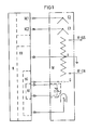
- the amplifier consists of the power supply unit N, the traveling wave tube W and the temperature-dependent network T, which measures the current tube temperature. Via control electronics in the power supply unit N, the cathode current in the traveling wave tube W can be kept almost constant by a voltage of the control electrode G which is dependent on this tube temperature.
- the traveling wave tube W consists essentially of the cathode K, the control electrode G, the coil H and the collectors C1 and C2.
- the power supply unit N is composed essentially of the collector voltage sources NC1 and NC2, the coil voltage source NH, the control voltage source NG and the temperature tracking NT.
- the HF inputs and outputs of the traveling wave tube W are indicated by arrows labeled "HF-ON" and "HF-OFF".
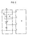
- the circuit 2 shows an implemented circuit.
- the circuit essentially consists of a high-voltage resistance divider X, Y and Z, the basic setting of the cathode current being made with the resistor Y.
- the temperature-dependent network T is connected in parallel with the resistor Z in such a way that the cross-current through the resistors X, Y and Z changes with the change in the resistance in the temperature-dependent network T and, as a result, there is a voltage change across the resistor X related to the cathode K.
- the voltage across the resistor X influences the cathode current via the control input of the control electrode G of the traveling wave tube W.
- the control voltage source is provided with the letters NG and the delay line, which is designed as a coil in this exemplary embodiment, is provided with the letter H.
Landscapes
- Engineering & Computer Science (AREA)
- Power Engineering (AREA)
- Microwave Tubes (AREA)
- Microwave Amplifiers (AREA)
- Amplifiers (AREA)
Claims (2)
Applications Claiming Priority (2)
| Application Number | Priority Date | Filing Date | Title |
|---|---|---|---|
| DE3311674 | 1983-03-30 | ||
| DE19833311674 DE3311674A1 (de) | 1983-03-30 | 1983-03-30 | Schaltungsanordnung zur temperaturabhaengigen kathodenstromnachfuehrung in wanderfeldroehren |
Publications (2)
| Publication Number | Publication Date |
|---|---|
| EP0121189A1 EP0121189A1 (fr) | 1984-10-10 |
| EP0121189B1 true EP0121189B1 (fr) | 1987-06-24 |
Family
ID=6195144
Family Applications (1)
| Application Number | Title | Priority Date | Filing Date |
|---|---|---|---|
| EP84103197A Expired EP0121189B1 (fr) | 1983-03-30 | 1984-03-22 | Circuit de contre-réaction pour la régulation de la tension de commandee en fonction de la température dans un tube á propagation d'ondes |
Country Status (5)
| Country | Link |
|---|---|
| US (1) | US4638215A (fr) |
| EP (1) | EP0121189B1 (fr) |
| JP (1) | JPS59184438A (fr) |
| CA (1) | CA1226909A (fr) |
| DE (2) | DE3311674A1 (fr) |
Families Citing this family (6)
| Publication number | Priority date | Publication date | Assignee | Title |
|---|---|---|---|---|
| JPH07101596B2 (ja) * | 1992-12-09 | 1995-11-01 | 株式会社宇宙通信基礎技術研究所 | 進行波管増幅器 |
| DE19710100A1 (de) * | 1997-03-12 | 1998-09-17 | Bosch Gmbh Robert | Anordnung insbesondere für die Ansteuerung einer Wanderfeldröhre |
| US7002301B2 (en) * | 2003-10-15 | 2006-02-21 | Lutron Electronics Co., Inc. | Apparatus and methods for making capacitive measurements of cathode fall in fluorescent lamps |
| US7116055B2 (en) * | 2003-10-15 | 2006-10-03 | Lutron Electronics Co., Inc. | Apparatus and methods for making spectroscopic measurements of cathode fall in fluorescent lamps |
| EP2296165A1 (fr) * | 2009-09-14 | 2011-03-16 | L-3 Communications Corporation | Canon à électrons commuté à élément double |
| US8492978B2 (en) * | 2009-09-14 | 2013-07-23 | L-3 Communications Corporation | Dual element switched electron gun |
Family Cites Families (5)
| Publication number | Priority date | Publication date | Assignee | Title |
|---|---|---|---|---|
| US3267322A (en) * | 1961-02-23 | 1966-08-16 | Varian Associates | Frequency stable temperature compensated electron tube |
| US3254265A (en) * | 1961-02-24 | 1966-05-31 | Varian Associates | Means for controlling frequency of an electron tube |
| US3316485A (en) * | 1962-10-08 | 1967-04-25 | Varian Associates | Beam current measurement by inductive techniques for high frequency electron discharge devices |
| FR2401510A1 (fr) * | 1977-04-29 | 1979-03-23 | Thomson Csf | Tube electronique a interaction d'un faisceau avec une onde, et notamment tube a onde progressive, a intensite de faisceau stabilisee |
| US4471265A (en) * | 1980-04-02 | 1984-09-11 | Telefonaktiebolaget L M Ericsson | Apparatus for counteracting the cathode current increase occurring during warming-up in a travelling-wave tube in response to variation in the grid-cathode distance |
-
1983
- 1983-03-30 DE DE19833311674 patent/DE3311674A1/de not_active Withdrawn
-
1984
- 1984-03-22 DE DE8484103197T patent/DE3464436D1/de not_active Expired
- 1984-03-22 EP EP84103197A patent/EP0121189B1/fr not_active Expired
- 1984-03-27 US US06/593,953 patent/US4638215A/en not_active Expired - Fee Related
- 1984-03-28 CA CA000450704A patent/CA1226909A/fr not_active Expired
- 1984-03-30 JP JP59063130A patent/JPS59184438A/ja active Pending
Also Published As
| Publication number | Publication date |
|---|---|
| EP0121189A1 (fr) | 1984-10-10 |
| US4638215A (en) | 1987-01-20 |
| JPS59184438A (ja) | 1984-10-19 |
| CA1226909A (fr) | 1987-09-15 |
| DE3464436D1 (en) | 1987-07-30 |
| DE3311674A1 (de) | 1984-10-04 |
Similar Documents
| Publication | Publication Date | Title |
|---|---|---|
| EP0348701A1 (fr) | Appareil pour mesurer la distance | |
| EP0121189B1 (fr) | Circuit de contre-réaction pour la régulation de la tension de commandee en fonction de la température dans un tube á propagation d'ondes | |
| DE69023388T2 (de) | Feuchtigkeitsmessgerät. | |
| DE2613423B2 (de) | Elektronisches Schaltgerät | |
| EP0049793A2 (fr) | Dispositif électronique de commutation fonctionnant sans contact | |
| DE3616588C2 (fr) | ||
| DE3329665C2 (fr) | ||
| EP0682305B1 (fr) | Circuit pour la génération d'un courant de référence | |
| EP0093933A1 (fr) | Appareil de soudage à modulation d'impulsion sous gaz protecteur | |
| DE2803430C3 (de) | Frequenzstabiler, amplitudengeregelter Oszillator | |
| DE2718904B2 (de) | Schaltungsanordnung zur Linearitätskorrektur für eine Kathodenstrahlröhre | |
| EP0071608B1 (fr) | Generateur de tension en dent de scie | |
| DE1491912C3 (de) | Modulator | |
| DE862784C (de) | Pendelrueckkopplungsempfangsschaltung, bei der die Pendelfrequenz in der gleichen Roehre erzeugt wird | |
| DE69303092T2 (de) | Elektrischer Schaltkreis mit Ortsoszillatorkreis und Ortsoszillator für einen solchen Schaltkreis | |
| EP0103709B1 (fr) | Dispositif de circuit pour la correction de la distorsion latérale en coussin | |
| DE2810734C3 (de) | Amplitudengeregelter Schwingkreisoszillator | |
| DE2814784C3 (de) | Schalteinrichtung | |
| DD132814B1 (de) | Schaltungsanordnung zur temperaturkompensation von nichtdispersiven infrarot-gasanalysatoren | |
| DE19545533A1 (de) | Elektromagnetische Fokussierschaltung für eine Kathodenstrahlröhre | |
| DE2443026C2 (de) | Demodulatorschaltung für AM-Signale | |
| DE1165074B (de) | Schaltungsanordnung zur Stabilisierung der Amplitude eines saegezahnfoermigen Stromes | |
| DE2801894A1 (de) | Gleichspannungs-steuereinrichtung | |
| DE1566020C3 (de) | Stromversorgungsanlage für eine Wanderfeldröhre | |
| DE3340034A1 (de) | Bipolarer analogschalter |
Legal Events
| Date | Code | Title | Description |
|---|---|---|---|
| PUAI | Public reference made under article 153(3) epc to a published international application that has entered the european phase |
Free format text: ORIGINAL CODE: 0009012 |
|
| AK | Designated contracting states |
Designated state(s): DE GB IT NL SE |
|
| 17P | Request for examination filed |
Effective date: 19850304 |
|
| GRAA | (expected) grant |
Free format text: ORIGINAL CODE: 0009210 |
|
| AK | Designated contracting states |
Kind code of ref document: B1 Designated state(s): DE GB IT NL SE |
|
| REF | Corresponds to: |
Ref document number: 3464436 Country of ref document: DE Date of ref document: 19870730 |
|
| ITF | It: translation for a ep patent filed | ||
| PLBE | No opposition filed within time limit |
Free format text: ORIGINAL CODE: 0009261 |
|
| STAA | Information on the status of an ep patent application or granted ep patent |
Free format text: STATUS: NO OPPOSITION FILED WITHIN TIME LIMIT |
|
| 26N | No opposition filed | ||
| ITTA | It: last paid annual fee | ||
| EAL | Se: european patent in force in sweden |
Ref document number: 84103197.4 |
|
| PGFP | Annual fee paid to national office [announced via postgrant information from national office to epo] |
Ref country code: NL Payment date: 19960219 Year of fee payment: 13 Ref country code: GB Payment date: 19960219 Year of fee payment: 13 |
|
| PGFP | Annual fee paid to national office [announced via postgrant information from national office to epo] |
Ref country code: DE Payment date: 19960221 Year of fee payment: 13 |
|
| PGFP | Annual fee paid to national office [announced via postgrant information from national office to epo] |
Ref country code: SE Payment date: 19960223 Year of fee payment: 13 |
|
| PG25 | Lapsed in a contracting state [announced via postgrant information from national office to epo] |
Ref country code: GB Effective date: 19970322 |
|
| PG25 | Lapsed in a contracting state [announced via postgrant information from national office to epo] |
Ref country code: SE Effective date: 19970323 |
|
| PG25 | Lapsed in a contracting state [announced via postgrant information from national office to epo] |
Ref country code: NL Effective date: 19971001 |
|
| GBPC | Gb: european patent ceased through non-payment of renewal fee |
Effective date: 19970322 |
|
| NLV4 | Nl: lapsed or anulled due to non-payment of the annual fee |
Effective date: 19971001 |
|
| PG25 | Lapsed in a contracting state [announced via postgrant information from national office to epo] |
Ref country code: DE Effective date: 19971202 |
|
| EUG | Se: european patent has lapsed |
Ref document number: 84103197.4 |