EP0121189B1 - Feedback circuit regulating the control voltage depending on the temperature in a travelling wave tube - Google Patents
Feedback circuit regulating the control voltage depending on the temperature in a travelling wave tube Download PDFInfo
- Publication number
- EP0121189B1 EP0121189B1 EP84103197A EP84103197A EP0121189B1 EP 0121189 B1 EP0121189 B1 EP 0121189B1 EP 84103197 A EP84103197 A EP 84103197A EP 84103197 A EP84103197 A EP 84103197A EP 0121189 B1 EP0121189 B1 EP 0121189B1
- Authority
- EP
- European Patent Office
- Prior art keywords
- temperature
- wave tube
- travelling wave
- tube
- cathode current
- Prior art date
- Legal status (The legal status is an assumption and is not a legal conclusion. Google has not performed a legal analysis and makes no representation as to the accuracy of the status listed.)
- Expired
Links
- 230000001105 regulatory effect Effects 0.000 title 1
- 230000001419 dependent effect Effects 0.000 claims description 12
- 238000010894 electron beam technology Methods 0.000 description 2
- 238000010438 heat treatment Methods 0.000 description 1
Images
Classifications
-
- H—ELECTRICITY
- H03—ELECTRONIC CIRCUITRY
- H03F—AMPLIFIERS
- H03F1/00—Details of amplifiers with only discharge tubes, only semiconductor devices or only unspecified devices as amplifying elements
- H03F1/30—Modifications of amplifiers to reduce influence of variations of temperature or supply voltage or other physical parameters
-
- H—ELECTRICITY
- H01—ELECTRIC ELEMENTS
- H01J—ELECTRIC DISCHARGE TUBES OR DISCHARGE LAMPS
- H01J23/00—Details of transit-time tubes of the types covered by group H01J25/00
- H01J23/34—Circuit arrangements not adapted to a particular application of the tube and not otherwise provided for
Definitions
- the invention relates to a traveling wave tube with a cathode for generating a cathode current, circuitry for keeping the cathode current constant.
- a traveling wave tube according to the preamble of claim 1 is known.
- the constant cathode current is achieved by a voltage variation on a control electrode, namely by tracking the control voltage.
- the voltage variation is determined so that the current through the cathode circuit is equal to a reference variable.
- US-A 3267322 describes how the temperature of a tube can be kept constant. To do this, the temperature of the tube shell is measured using a temperature-dependent network. Depending on the measured temperature change, the electron beam is more or less focused on a collector by an electron lens. If the electron beam is not focused, it hits the lens electrode and heats it up so that the temperature change is reversed. This stabilizes the temperature and thus the frequency of the tube.
- the object of the present invention is to achieve a temperature-dependent tracking of the control voltage in order to obtain a relatively constant cathode current by heating the traveling wave tube.
- this object is achieved in that the circuit arrangement is thermally coupled to the traveling wave tube and contains a temperature-dependent network which measures the tube temperature and, via control electronics in a power supply unit, by means of a voltage on the control electrode of the traveling wave tube which is dependent on this tube temperature, the preselected cathode current is almost constant holds.
- the circuit arrangement is preferably mounted in the vicinity of the control electrodes determining the cathode current and thermally coupled to them.
- the traveling wave tube according to the invention with a circuit arrangement for keeping the cathode current constant has the advantage that an integrated circuit arranged at a suitable point on the traveling wave tube measures the current tube temperature as a temperature-dependent network and preferably uses an electrically conductive connection to track the control voltage via a control input in the power supply in such a way that over a wide temperature range of almost constant cathode current flows and the output power accordingly remains constant.
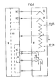
- the amplifier consists of the power supply unit N, the traveling wave tube W and the temperature-dependent network T, which measures the current tube temperature. Via control electronics in the power supply unit N, the cathode current in the traveling wave tube W can be kept almost constant by a voltage of the control electrode G which is dependent on this tube temperature.
- the traveling wave tube W consists essentially of the cathode K, the control electrode G, the coil H and the collectors C1 and C2.
- the power supply unit N is composed essentially of the collector voltage sources NC1 and NC2, the coil voltage source NH, the control voltage source NG and the temperature tracking NT.
- the HF inputs and outputs of the traveling wave tube W are indicated by arrows labeled "HF-ON" and "HF-OFF".
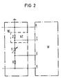
- the circuit 2 shows an implemented circuit.
- the circuit essentially consists of a high-voltage resistance divider X, Y and Z, the basic setting of the cathode current being made with the resistor Y.
- the temperature-dependent network T is connected in parallel with the resistor Z in such a way that the cross-current through the resistors X, Y and Z changes with the change in the resistance in the temperature-dependent network T and, as a result, there is a voltage change across the resistor X related to the cathode K.
- the voltage across the resistor X influences the cathode current via the control input of the control electrode G of the traveling wave tube W.
- the control voltage source is provided with the letters NG and the delay line, which is designed as a coil in this exemplary embodiment, is provided with the letter H.
Landscapes
- Engineering & Computer Science (AREA)
- Power Engineering (AREA)
- Microwave Tubes (AREA)
- Microwave Amplifiers (AREA)
- Amplifiers (AREA)
Description
Die Erfindung betrifft eine Wanderfeldröhre mit einer Kathode zur Erzeugung eines Kathodenstroms, Schaltungsanordnung zur Konstanthaltung des Kathodenstroms.The invention relates to a traveling wave tube with a cathode for generating a cathode current, circuitry for keeping the cathode current constant.
Aus der FR-A 2401510 ist eine Wanderfeldröhre gemäss dem Oberbegriff des Patentanspruchs 1 bekannt. Der konstante Kathodenstrom wird durch eine Spannungsvariation an einer Steuerelektrode erreicht, und zwar durch Nachführung der Steuerspannung. Die Spannungsvariation wird so bestimmt, dass der Strom durch den Kathodenkreis gleich einer Bezugsgrösse ist.From FR-A 2401510 a traveling wave tube according to the preamble of claim 1 is known. The constant cathode current is achieved by a voltage variation on a control electrode, namely by tracking the control voltage. The voltage variation is determined so that the current through the cathode circuit is equal to a reference variable.
In der US-A 3267322 ist beschrieben, wie die Temperatur einer Röhre konstant gehalten werden kann. Dazu wird die Temperatur der Hülle der Röhre mit einem temperaturabhängigen Netzwerk gemessen. Abhängig von der gemessenen Temperaturänderung wird der Elektronenstrahl von einer Elektronenlinse mehr oder weniger auf einem Kollektor fokussiert. Wenn der Elektronenstrahl nicht fokussiert ist, trifft er auf die Linsenelektrode und erwärmt diese so, dass die Temperaturänderung rückgängig gemacht wird. So wird die Temperatur und dadurch die Frequenz der Röhre stabilisiert.US-A 3267322 describes how the temperature of a tube can be kept constant. To do this, the temperature of the tube shell is measured using a temperature-dependent network. Depending on the measured temperature change, the electron beam is more or less focused on a collector by an electron lens. If the electron beam is not focused, it hits the lens electrode and heats it up so that the temperature change is reversed. This stabilizes the temperature and thus the frequency of the tube.
Bei einer konstant anliegenden Steuerspannung ist der Kathodenstrom und damit die Verstärkung einer Wanderfeldröhre inkonstant bei Temperaturveränderungen. Der Grund hierfür liegt in der temperaturabhängigen Änderung des Steuerelektrode-Kathodenabstandes in der Röhre.With a constant control voltage, the cathode current and thus the gain of a traveling wave tube is inconsistent with temperature changes. The reason for this lies in the temperature-dependent change in the control electrode-cathode distance in the tube.
Der vorligenden Erfindung liegt die Aufgabe zugrunde, eine temperaturabhängige Nachführung der Steuerspannung zu erreichen, um einen relativ konstanten Kathodenstrom über die Erwärmung der Wanderfeldröhre zu erhalten.The object of the present invention is to achieve a temperature-dependent tracking of the control voltage in order to obtain a relatively constant cathode current by heating the traveling wave tube.
Diese Aufgabe wird erfindungsgemäss dadurch gelöst, dass die Schaltungsanordnung mit der Wanderfeldröhre thermisch gekoppelt ist und ein temperaturabhängiges Netzwerk enthält, welches die Röhrentemperatur misst und über eine Steuerelektronik in einem Netzgerät durch eine von dieser Röhrentemperatur abhängige Spannung an der Steuerelektrode der Wanderfeldröhre den vorgewählten Kathodenstrom nahezu konstant hält.According to the invention, this object is achieved in that the circuit arrangement is thermally coupled to the traveling wave tube and contains a temperature-dependent network which measures the tube temperature and, via control electronics in a power supply unit, by means of a voltage on the control electrode of the traveling wave tube which is dependent on this tube temperature, the preselected cathode current is almost constant holds.
Die Schaltungsanordnung ist dabei vorzugsweise in der Nähe der den Kathodenstrom bestimmenden Steuerelektroden angebracht und mit diesen thermisch gekoppelt.The circuit arrangement is preferably mounted in the vicinity of the control electrodes determining the cathode current and thermally coupled to them.
Die erfindungsgemässe Wanderfeldröhre mit einer Schaltungsanordnung zur Konstanthaltung des Kathodenstroms hat den Vorteil, dass eine an geeigneter Stelle der Wanderfeldröhre angeordnete integrierte Schaltung als temperaturabhängiges Netzwerk die aktuelle Röhrentemperatur misst und über eine elektrisch leitende Verbindung vorzugsweise die Steuerspannung über einen Steuereingang im Netzgerät dergestalt nachführt, dass über einen weiten Temperaturbereich nahezu konstanter Kathodenstrom fliesst und die Ausgangsleistung dementsprechend konstant bleibt.The traveling wave tube according to the invention with a circuit arrangement for keeping the cathode current constant has the advantage that an integrated circuit arranged at a suitable point on the traveling wave tube measures the current tube temperature as a temperature-dependent network and preferably uses an electrically conductive connection to track the control voltage via a control input in the power supply in such a way that over a wide temperature range of almost constant cathode current flows and the output power accordingly remains constant.
Die Erfindung wird anhand der Figuren der Zeichnung weiter erläutert. Es zeigen:
- Fig. den prinzipiellen Aufbau eines Wanderfeldröhrenverstärkers mit Temperaturkompensation und
- Fig. 2 eine ausgeführte Schaltung.
- Fig. The basic structure of a traveling wave tube amplifier with temperature compensation and
- Fig. 2 shows an executed circuit.
In Fig. 1 ist der prinzipielle Aufbau eines Wanderfeldröhrenverstärkers mit Temperaturkompensation dargestellt. Der Verstärker besteht aus dem Netzgerät N, der Wanderfeldröhre W und dem temperaturabhängigen Netzwerk T, welches die aktuelle Röhrentemperatur misst. Über eine Steuerelektronik im Netzgerät N lässt sich dabei der Kathodenstrom in der Wanderfeldröhre W durch eine von dieser Röhrentemperatur abhängige Spannung Steuerelektrode G, nahezu konstant halten. In diesem Ausführungsbeispiel besteht die Wanderfeldröhre W im wesentlichen aus der Kathode K, der Steuerelektrode G, der Wendel H sowie den Kollektoren C1 und C2. Das Netzgerät N setzt sich im wesentlichen aus den Kollektorspannungsquellen NC1 und NC2, der Wendelspannungsquelle NH, der Steuerspannungsquelle NG und der Temperaturnachführung NT zusammen. Die HF-Ein- und Ausgänge der Wanderfeldröhre W sind durch mit «Hf-EIN» und «HF-AUS» bezeichnete Pfeile angedeutet.1 shows the basic structure of a traveling wave tube amplifier with temperature compensation. The amplifier consists of the power supply unit N, the traveling wave tube W and the temperature-dependent network T, which measures the current tube temperature. Via control electronics in the power supply unit N, the cathode current in the traveling wave tube W can be kept almost constant by a voltage of the control electrode G which is dependent on this tube temperature. In this embodiment, the traveling wave tube W consists essentially of the cathode K, the control electrode G, the coil H and the collectors C1 and C2. The power supply unit N is composed essentially of the collector voltage sources NC1 and NC2, the coil voltage source NH, the control voltage source NG and the temperature tracking NT. The HF inputs and outputs of the traveling wave tube W are indicated by arrows labeled "HF-ON" and "HF-OFF".
In Fig. 2 ist eine ausgeführte Schaltung dargestellt. Die Schaltung besteht im wesentlichen aus einem Hochspannungswiderstandsteiler X, Y und Z, wobei mit dem Widerstand Y die Grundeinstellung des Kathodenstromes erfolgt. Dem Widerstand Z ist das temperaturabhängige Netzwerk T parallel geschaltet, derart, dass sich der Querstrom durch die Widerstände X, Y und Z mit der Änderung des Widerstandes im temperaturabhängigen Netzwerk T ändert und damit einhergehend eine auf die Kathode K bezogene Spannungsänderung am Widerstand X erfolgt. Die Spannung am Widerstand X beeinflusst über den Steuereingang der Steuerelektrode G der Wanderfeldröhre W den Kathodenstrom. Entsprechend Fig. 1 sind die Steuerspannungsquelle mit den Buchstaben NG und die in diesem Ausführungsbeispiel als Wendel ausgebildete Verzögerungsleitung mit dem Buchstaben H versehen.2 shows an implemented circuit. The circuit essentially consists of a high-voltage resistance divider X, Y and Z, the basic setting of the cathode current being made with the resistor Y. The temperature-dependent network T is connected in parallel with the resistor Z in such a way that the cross-current through the resistors X, Y and Z changes with the change in the resistance in the temperature-dependent network T and, as a result, there is a voltage change across the resistor X related to the cathode K. The voltage across the resistor X influences the cathode current via the control input of the control electrode G of the traveling wave tube W. According to FIG. 1, the control voltage source is provided with the letters NG and the delay line, which is designed as a coil in this exemplary embodiment, is provided with the letter H.
Claims (2)
Applications Claiming Priority (2)
| Application Number | Priority Date | Filing Date | Title |
|---|---|---|---|
| DE3311674 | 1983-03-30 | ||
| DE19833311674 DE3311674A1 (en) | 1983-03-30 | 1983-03-30 | CIRCUIT ARRANGEMENT FOR TEMPERATURE-DEPENDENT CATHODE CURRENT LEVELING IN WALKER PIPES |
Publications (2)
| Publication Number | Publication Date |
|---|---|
| EP0121189A1 EP0121189A1 (en) | 1984-10-10 |
| EP0121189B1 true EP0121189B1 (en) | 1987-06-24 |
Family
ID=6195144
Family Applications (1)
| Application Number | Title | Priority Date | Filing Date |
|---|---|---|---|
| EP84103197A Expired EP0121189B1 (en) | 1983-03-30 | 1984-03-22 | Feedback circuit regulating the control voltage depending on the temperature in a travelling wave tube |
Country Status (5)
| Country | Link |
|---|---|
| US (1) | US4638215A (en) |
| EP (1) | EP0121189B1 (en) |
| JP (1) | JPS59184438A (en) |
| CA (1) | CA1226909A (en) |
| DE (2) | DE3311674A1 (en) |
Families Citing this family (6)
| Publication number | Priority date | Publication date | Assignee | Title |
|---|---|---|---|---|
| JPH07101596B2 (en) * | 1992-12-09 | 1995-11-01 | 株式会社宇宙通信基礎技術研究所 | Traveling wave tube amplifier |
| DE19710100A1 (en) * | 1997-03-12 | 1998-09-17 | Bosch Gmbh Robert | Arrangement especially for the control of a traveling wave tube |
| US7002301B2 (en) * | 2003-10-15 | 2006-02-21 | Lutron Electronics Co., Inc. | Apparatus and methods for making capacitive measurements of cathode fall in fluorescent lamps |
| US7116055B2 (en) * | 2003-10-15 | 2006-10-03 | Lutron Electronics Co., Inc. | Apparatus and methods for making spectroscopic measurements of cathode fall in fluorescent lamps |
| EP2296165A1 (en) * | 2009-09-14 | 2011-03-16 | L-3 Communications Corporation | Dual element switched electron gun |
| US8492978B2 (en) * | 2009-09-14 | 2013-07-23 | L-3 Communications Corporation | Dual element switched electron gun |
Family Cites Families (5)
| Publication number | Priority date | Publication date | Assignee | Title |
|---|---|---|---|---|
| US3267322A (en) * | 1961-02-23 | 1966-08-16 | Varian Associates | Frequency stable temperature compensated electron tube |
| US3254265A (en) * | 1961-02-24 | 1966-05-31 | Varian Associates | Means for controlling frequency of an electron tube |
| US3316485A (en) * | 1962-10-08 | 1967-04-25 | Varian Associates | Beam current measurement by inductive techniques for high frequency electron discharge devices |
| FR2401510A1 (en) * | 1977-04-29 | 1979-03-23 | Thomson Csf | Stabilised beam travelling wave tube - employs operational amplifier comparator and zener reference source |
| US4471265A (en) * | 1980-04-02 | 1984-09-11 | Telefonaktiebolaget L M Ericsson | Apparatus for counteracting the cathode current increase occurring during warming-up in a travelling-wave tube in response to variation in the grid-cathode distance |
-
1983
- 1983-03-30 DE DE19833311674 patent/DE3311674A1/en not_active Withdrawn
-
1984
- 1984-03-22 DE DE8484103197T patent/DE3464436D1/en not_active Expired
- 1984-03-22 EP EP84103197A patent/EP0121189B1/en not_active Expired
- 1984-03-27 US US06/593,953 patent/US4638215A/en not_active Expired - Fee Related
- 1984-03-28 CA CA000450704A patent/CA1226909A/en not_active Expired
- 1984-03-30 JP JP59063130A patent/JPS59184438A/en active Pending
Also Published As
| Publication number | Publication date |
|---|---|
| EP0121189A1 (en) | 1984-10-10 |
| US4638215A (en) | 1987-01-20 |
| JPS59184438A (en) | 1984-10-19 |
| CA1226909A (en) | 1987-09-15 |
| DE3464436D1 (en) | 1987-07-30 |
| DE3311674A1 (en) | 1984-10-04 |
Similar Documents
| Publication | Publication Date | Title |
|---|---|---|
| EP0348701A1 (en) | Device for distance measurement | |
| EP0121189B1 (en) | Feedback circuit regulating the control voltage depending on the temperature in a travelling wave tube | |
| DE69023388T2 (en) | Moisture meter. | |
| DE2613423B2 (en) | Electronic switchgear | |
| EP0049793A2 (en) | Contactless electronic switching device | |
| DE3616588C2 (en) | ||
| DE3329665C2 (en) | ||
| EP0682305B1 (en) | Circuit device for generating a reference current | |
| EP0093933A1 (en) | Pulse welding apparatus for gas-shielded welding | |
| DE2803430C3 (en) | Frequency-stable, amplitude-controlled oscillator | |
| DE2718904B2 (en) | Circuit arrangement for linearity correction for a cathode ray tube | |
| EP0071608B1 (en) | Saw-tooth voltage generator | |
| DE1491912C3 (en) | modulator | |
| DE862784C (en) | Pendulum feedback receiving circuit in which the pendulum frequency is generated in the same tube | |
| DE69303092T2 (en) | Electrical circuit with local oscillator circuit and local oscillator for such a circuit | |
| EP0103709B1 (en) | Circuit arrangement for the correction of e-w pin cushion corrections | |
| DE2810734C3 (en) | Amplitude-controlled resonant circuit oscillator | |
| DE2814784C3 (en) | Switching device | |
| DD132814B1 (en) | CIRCUIT ARRANGEMENT FOR TEMPERATURE COMPENSATION OF NON-DISPERSIVE INFRARED GAS ANALYZERS | |
| DE19545533A1 (en) | Electromagnetic focusing appts. for cathode ray tube | |
| DE2443026C2 (en) | Demodulator circuit for AM signals | |
| DE1165074B (en) | Circuit arrangement for stabilizing the amplitude of a saw tooth-shaped current | |
| DE2801894A1 (en) | DC VOLTAGE CONTROL DEVICE | |
| DE1566020C3 (en) | Power supply system for a traveling wave tube | |
| DE3340034A1 (en) | Bipolar analog switch |
Legal Events
| Date | Code | Title | Description |
|---|---|---|---|
| PUAI | Public reference made under article 153(3) epc to a published international application that has entered the european phase |
Free format text: ORIGINAL CODE: 0009012 |
|
| AK | Designated contracting states |
Designated state(s): DE GB IT NL SE |
|
| 17P | Request for examination filed |
Effective date: 19850304 |
|
| GRAA | (expected) grant |
Free format text: ORIGINAL CODE: 0009210 |
|
| AK | Designated contracting states |
Kind code of ref document: B1 Designated state(s): DE GB IT NL SE |
|
| REF | Corresponds to: |
Ref document number: 3464436 Country of ref document: DE Date of ref document: 19870730 |
|
| ITF | It: translation for a ep patent filed | ||
| PLBE | No opposition filed within time limit |
Free format text: ORIGINAL CODE: 0009261 |
|
| STAA | Information on the status of an ep patent application or granted ep patent |
Free format text: STATUS: NO OPPOSITION FILED WITHIN TIME LIMIT |
|
| 26N | No opposition filed | ||
| ITTA | It: last paid annual fee | ||
| EAL | Se: european patent in force in sweden |
Ref document number: 84103197.4 |
|
| PGFP | Annual fee paid to national office [announced via postgrant information from national office to epo] |
Ref country code: NL Payment date: 19960219 Year of fee payment: 13 Ref country code: GB Payment date: 19960219 Year of fee payment: 13 |
|
| PGFP | Annual fee paid to national office [announced via postgrant information from national office to epo] |
Ref country code: DE Payment date: 19960221 Year of fee payment: 13 |
|
| PGFP | Annual fee paid to national office [announced via postgrant information from national office to epo] |
Ref country code: SE Payment date: 19960223 Year of fee payment: 13 |
|
| PG25 | Lapsed in a contracting state [announced via postgrant information from national office to epo] |
Ref country code: GB Effective date: 19970322 |
|
| PG25 | Lapsed in a contracting state [announced via postgrant information from national office to epo] |
Ref country code: SE Effective date: 19970323 |
|
| PG25 | Lapsed in a contracting state [announced via postgrant information from national office to epo] |
Ref country code: NL Effective date: 19971001 |
|
| GBPC | Gb: european patent ceased through non-payment of renewal fee |
Effective date: 19970322 |
|
| NLV4 | Nl: lapsed or anulled due to non-payment of the annual fee |
Effective date: 19971001 |
|
| PG25 | Lapsed in a contracting state [announced via postgrant information from national office to epo] |
Ref country code: DE Effective date: 19971202 |
|
| EUG | Se: european patent has lapsed |
Ref document number: 84103197.4 |