EP0121189A1 - Feedback circuit regulating the control voltage depending on the temperature in a travelling wave tube - Google Patents
Feedback circuit regulating the control voltage depending on the temperature in a travelling wave tube Download PDFInfo
- Publication number
- EP0121189A1 EP0121189A1 EP84103197A EP84103197A EP0121189A1 EP 0121189 A1 EP0121189 A1 EP 0121189A1 EP 84103197 A EP84103197 A EP 84103197A EP 84103197 A EP84103197 A EP 84103197A EP 0121189 A1 EP0121189 A1 EP 0121189A1
- Authority
- EP
- European Patent Office
- Prior art keywords
- temperature
- traveling wave
- circuit arrangement
- wave tube
- tube
- Prior art date
- Legal status (The legal status is an assumption and is not a legal conclusion. Google has not performed a legal analysis and makes no representation as to the accuracy of the status listed.)
- Granted
Links
Images

Classifications
-
- H—ELECTRICITY
- H03—ELECTRONIC CIRCUITRY
- H03F—AMPLIFIERS
- H03F1/00—Details of amplifiers with only discharge tubes, only semiconductor devices or only unspecified devices as amplifying elements
- H03F1/30—Modifications of amplifiers to reduce influence of variations of temperature or supply voltage or other physical parameters
-
- H—ELECTRICITY
- H01—ELECTRIC ELEMENTS
- H01J—ELECTRIC DISCHARGE TUBES OR DISCHARGE LAMPS
- H01J23/00—Details of transit-time tubes of the types covered by group H01J25/00
- H01J23/34—Circuit arrangements not adapted to a particular application of the tube and not otherwise provided for
Definitions
- the invention relates to a circuit arrangement for temperature-dependent cathode current tracking in traveling wave tubes.
- the object of the present invention is to achieve a temperature-dependent tracking of the control voltage in order to obtain a relatively constant cathode current by heating the tube.
- This object is achieved in that the circuit arrangement is thermally coupled at a suitable point with the traveling wave tube and consists of a temperature-dependent network which measures the current tube temperature and via control electronics in the power supply by voltage variation on a control electrode of the traveling wave tube, the preselected cathode current almost constant can hold.
- the circuit arrangement is preferably in the vicinity of the control electrodes determining the cathode current. attached and thermally sufficiently well coupled.
- the circuit arrangement according to the invention has the advantage that an integrated circuit, consisting of a temperature-dependent network, which is arranged at a suitable point on the tube, measures the current tube temperature and, via an electrically conductive connection, preferably tracks the G 2 voltage via a control input in the power supply unit such that a Almost constant cathode current flows over a wide temperature range and the output power accordingly remains constant.
- the amplifier consists of the power supply unit N, the traveling wave tube W and the temperature-dependent network T, which measures the current tube temperature.
- the cathode current in the traveling wave tube W can be kept almost constant by varying the voltage on a control electrode, for example control electrode G.
- the traveling wave tube W essentially consists of the cathode K, the grid G, the filament H and the collectors C 1 and C 2.
- the power supply unit N is composed essentially of the collector voltage sources NC 1 and NC 2, the filament voltage source NH, the grid voltage source NG and the temperature tracking NT together.
- the HF inputs and outputs of the traveling wave tube W are indicated by arrows labeled HF-ON and HF-AUS.
- the circuit essentially consists of a high-voltage resistance divider X, Y and Z, the basic setting of the cathode current being made with the resistor Y.
- the temperature-dependent network T is connected in parallel with the resistor Z in such a way that the cross-current through the resistors X, Y and Z changes with the change in the resistance in the temperature-dependent network T and a voltage change at the resistor X related to the cathode K is associated therewith.
- the voltage across the resistor X influences the cathode current via the control input G of the traveling wave tube W.
- the grid voltage source is provided with the letters NG and the delay line, which is designed as a coil in this exemplary embodiment, is provided with the letter H.
Landscapes
- Engineering & Computer Science (AREA)
- Power Engineering (AREA)
- Microwave Tubes (AREA)
- Microwave Amplifiers (AREA)
- Amplifiers (AREA)
Abstract
Die Erfindung bezieht sich auf eine Schaltungsanordnung zur Temperaturabhängigen Kathodenstromnachführung in Wanderfeldröhren. Mit dieser Schaltungsanordnung soll, um einen relativ konstanten Kathodenstrom über die Erwärmung der Röhre zu erhalten, eine temperaturabhängige Nachführung der Steuerspannung erreicht werden. Die Erfindung sieht hierzu vor, daß die Schaltungsanordnung an einer geeigneten Stelle mit der Wanderfeldröhre (W) thermisch verkoppelt ist und aus einem temperaturabhängigen Netzwerk (T) besteht, welches die aktuelle Röhrentemperatur mißt und über eine Steuerelektronik (NT) im Netzgerät (N) durch Spannungsvariation an einer Steuerelektrode (G) der Wanderfeldröhre (W) den vorgewählten Kathodenstrom nehezu konstant halten läßt. Die erfindungsgemäße Schaltungsanordnung wird bei Wanderfeldröhrenverstärkern angewendet.The invention relates to a circuit arrangement for temperature-dependent cathode current tracking in traveling wave tubes. With this circuit arrangement, in order to obtain a relatively constant cathode current by heating the tube, a temperature-dependent tracking of the control voltage is to be achieved. For this purpose, the invention provides that the circuit arrangement is thermally coupled to the traveling wave tube (W) at a suitable point and consists of a temperature-dependent network (T) which measures the current tube temperature and via control electronics (NT) in the power supply unit (N) Voltage variation on a control electrode (G) of the traveling wave tube (W) keeps the preselected cathode current almost constant. The circuit arrangement according to the invention is used in traveling wave tube amplifiers.
Description
Die Erfindung betrifft eine Schaltungsanordnung zur temperaturabhängigen Kathodenstromnachführung in Wanderfeldröhren.The invention relates to a circuit arrangement for temperature-dependent cathode current tracking in traveling wave tubes.
Bei einer konstant anliegenden Steuerspannung ist der Kathodenstrom und damit die Verstärkung einer Wanderfeldröhre inkonstant bei Temperaturveränderungen. Der Grund hierfür liegt in der temperaturabhängigen Änderung des Gitter-Kathodenabstandes in der Röhre.With a constant control voltage, the cathode current and thus the gain of a traveling wave tube is inconsistent with temperature changes. The reason for this lies in the temperature-dependent change in the grid-cathode distance in the tube.
Der vorliegenden Erfindung liegt die Aufgabe zugrunde, um einen relativ konstanten Kathodenstrom über die Erwärmung der Röhre zu erhalten, eine temperaturabhängige Nachführung der Steuerspannung zu erreichen. Diese Aufgabe wird erfindungsgemäß dadurch gelöst, daß die Schaltungsanordnung an einer geeigneten Stelle mit der Wanderfeldröhre thermisch verkoppelt ist und aus einem temperaturabhängigen Netzwerk besteht, welches die aktuelle Röhrentemperatur mißt und über eine Steuerelektronik im Netzgerät durch Spannungsvariation an einer Steuerelektrode der Wanderfeldröhre den vorgewählten Kathodenstrom nahezu konstant halten läßt. Die Schaltungsanordnung ist dabei vorzugsweise in der Nähe der den Kathodenstrom bestimmenden Steuerelektroden . angebracht und thermisch ausreichend gut verkoppelt.The object of the present invention is to achieve a temperature-dependent tracking of the control voltage in order to obtain a relatively constant cathode current by heating the tube. This object is achieved in that the circuit arrangement is thermally coupled at a suitable point with the traveling wave tube and consists of a temperature-dependent network which measures the current tube temperature and via control electronics in the power supply by voltage variation on a control electrode of the traveling wave tube, the preselected cathode current almost constant can hold. The circuit arrangement is preferably in the vicinity of the control electrodes determining the cathode current. attached and thermally sufficiently well coupled.
Die erfindungsgemäße Schaltungsanordnung hat den Vorteil, daß eine an geeigneter Stelle der Röhre angeordnete integrierte Schaltung, bestehend aus einem temperaturabhängigen Netzwerk, die aktuelle Röhrentemperatur mißt und über eine elektrisch leitende Verbindung vorzugsweise die G 2-Spannung über einen Steuereingang im Netzgerät dergestalt nachführt, daß ein über einen weiten Temperaturbereich nahezu konstanter Kathodenstrom fließt und die Ausgangsleistung dementsprechend konstant bleibt.The circuit arrangement according to the invention has the advantage that an integrated circuit, consisting of a temperature-dependent network, which is arranged at a suitable point on the tube, measures the current tube temperature and, via an electrically conductive connection, preferably tracks the G 2 voltage via a control input in the power supply unit such that a Almost constant cathode current flows over a wide temperature range and the output power accordingly remains constant.
Die Erfindung wird anhand der Figuren der Zeichnung weiter erläutert. Es zeigen:
- Fig. 1 den prinzipiellen Aufbau eines Wanderfeldröhrenverstärkers mit Temperaturkompensation und
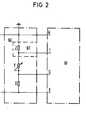
- Fig. 2 eine ausgeführte Schaltung.
- Fig. 1 shows the basic structure of a traveling wave tube amplifier with temperature compensation and
- Fig. 2 shows an executed circuit.
In Fig. 1 ist der prinzipielle Aufbau eines Wanderfeldröhrenverstärkers mit Temperaturkompensation dargestellt. Der Verstärker besteht aus dem Netzgerät N, aus der Wanderfeldröhre W und dem temperaturabhängigen Netzwerk T, welches die aktuelle Röhrentemperatur mißt. Über eine Steuerelektronik im Netzgerät N läßt sich dabei der Kathodenstrom in der Wanderfeldröhre W durch Spannungsvariation an einer Steuerelektrode, beispielsweise Steuerelektrode G, nahezu konstant halten. In diesem Ausführungsbeispiel besteht die Wanderfeldröhre W im wesentlichen aus der Kathode K, dem Gitter G, der Wendel H sowie den Kollektoren C 1 und C 2. Das Netzgerät N setzt sich im wesentlichen aus den Kollektorspannungsquellen NC 1 und NC 2, der Wendelspannungsquelle NH, der Gitterspannungsquelle NG und der Temperaturnachführung NT zusammen. Die HF-Ein- und Ausgänge der Wanderfeldröhre W sind durch mit HF-EIN und HF-AUS bezeichnete Pfeile angedeutet.1 shows the basic structure of a traveling wave tube amplifier with temperature compensation. The amplifier consists of the power supply unit N, the traveling wave tube W and the temperature-dependent network T, which measures the current tube temperature. Via control electronics in the power supply unit N, the cathode current in the traveling wave tube W can be kept almost constant by varying the voltage on a control electrode, for example control electrode G. In this exemplary embodiment, the traveling wave tube W essentially consists of the cathode K, the grid G, the filament H and the
In Fig. 2 ist eine ausgeführte Schaltung dargestellt. Die Schaltung besteht im wesentlichen aus einem Hochspannungswiderstandsteiler X,Y und Z, wobei mit dem Widerstand Y die Grundeinstellung des Kathodenstromes erfolgt. Dem Widerstand Z ist das temperaturabhängige Netzwerk T parallel geschaltet, derart, daß sich der Querstrom durch die Widerstände X, Y und Z mit der Änderung des Widerstandes im temperaturabhänigen Netzwerk T ändert und damit einhergehend eine auf die Kathode K bezogene Spannungsänderung am Widerstand X erfolgt. Die Spannung am Widerstand X beeinflußt über den Steuereingang G der Wanderfeldröhre W den Kathodenstrom. Entsprechend Fig. 1 ist die Gitterspannungsquelle mit den Buchstaben NG und die in diesem Ausführungsbeispiel als Wendel ausgebildete Verzögerungsleitung mit dem Buchstaben H versehen.2 shows an implemented circuit. The circuit essentially consists of a high-voltage resistance divider X, Y and Z, the basic setting of the cathode current being made with the resistor Y. The temperature-dependent network T is connected in parallel with the resistor Z in such a way that the cross-current through the resistors X, Y and Z changes with the change in the resistance in the temperature-dependent network T and a voltage change at the resistor X related to the cathode K is associated therewith. The voltage across the resistor X influences the cathode current via the control input G of the traveling wave tube W. According to FIG. 1, the grid voltage source is provided with the letters NG and the delay line, which is designed as a coil in this exemplary embodiment, is provided with the letter H.
Claims (2)
Applications Claiming Priority (2)
| Application Number | Priority Date | Filing Date | Title |
|---|---|---|---|
| DE3311674 | 1983-03-30 | ||
| DE19833311674 DE3311674A1 (en) | 1983-03-30 | 1983-03-30 | CIRCUIT ARRANGEMENT FOR TEMPERATURE-DEPENDENT CATHODE CURRENT LEVELING IN WALKER PIPES |
Publications (2)
| Publication Number | Publication Date |
|---|---|
| EP0121189A1 true EP0121189A1 (en) | 1984-10-10 |
| EP0121189B1 EP0121189B1 (en) | 1987-06-24 |
Family
ID=6195144
Family Applications (1)
| Application Number | Title | Priority Date | Filing Date |
|---|---|---|---|
| EP84103197A Expired EP0121189B1 (en) | 1983-03-30 | 1984-03-22 | Feedback circuit regulating the control voltage depending on the temperature in a travelling wave tube |
Country Status (5)
| Country | Link |
|---|---|
| US (1) | US4638215A (en) |
| EP (1) | EP0121189B1 (en) |
| JP (1) | JPS59184438A (en) |
| CA (1) | CA1226909A (en) |
| DE (2) | DE3311674A1 (en) |
Families Citing this family (6)
| Publication number | Priority date | Publication date | Assignee | Title |
|---|---|---|---|---|
| JPH07101596B2 (en) * | 1992-12-09 | 1995-11-01 | 株式会社宇宙通信基礎技術研究所 | Traveling wave tube amplifier |
| DE19710100A1 (en) * | 1997-03-12 | 1998-09-17 | Bosch Gmbh Robert | Arrangement especially for the control of a traveling wave tube |
| US7002301B2 (en) * | 2003-10-15 | 2006-02-21 | Lutron Electronics Co., Inc. | Apparatus and methods for making capacitive measurements of cathode fall in fluorescent lamps |
| US7116055B2 (en) * | 2003-10-15 | 2006-10-03 | Lutron Electronics Co., Inc. | Apparatus and methods for making spectroscopic measurements of cathode fall in fluorescent lamps |
| US8492978B2 (en) * | 2009-09-14 | 2013-07-23 | L-3 Communications Corporation | Dual element switched electron gun |
| EP2296165A1 (en) * | 2009-09-14 | 2011-03-16 | L-3 Communications Corporation | Dual element switched electron gun |
Citations (5)
| Publication number | Priority date | Publication date | Assignee | Title |
|---|---|---|---|---|
| US3254265A (en) * | 1961-02-24 | 1966-05-31 | Varian Associates | Means for controlling frequency of an electron tube |
| US3267322A (en) * | 1961-02-23 | 1966-08-16 | Varian Associates | Frequency stable temperature compensated electron tube |
| US3316485A (en) * | 1962-10-08 | 1967-04-25 | Varian Associates | Beam current measurement by inductive techniques for high frequency electron discharge devices |
| FR2401510A1 (en) * | 1977-04-29 | 1979-03-23 | Thomson Csf | Stabilised beam travelling wave tube - employs operational amplifier comparator and zener reference source |
| EP0037385A2 (en) * | 1980-04-02 | 1981-10-07 | Telefonaktiebolaget L M Ericsson | Apparatus for counteracting the cathode current increase occurring during warming-up in a travelling-wave tube in response to variation in the grid-cathode distance |
-
1983
- 1983-03-30 DE DE19833311674 patent/DE3311674A1/en not_active Withdrawn
-
1984
- 1984-03-22 EP EP84103197A patent/EP0121189B1/en not_active Expired
- 1984-03-22 DE DE8484103197T patent/DE3464436D1/en not_active Expired
- 1984-03-27 US US06/593,953 patent/US4638215A/en not_active Expired - Fee Related
- 1984-03-28 CA CA000450704A patent/CA1226909A/en not_active Expired
- 1984-03-30 JP JP59063130A patent/JPS59184438A/en active Pending
Patent Citations (5)
| Publication number | Priority date | Publication date | Assignee | Title |
|---|---|---|---|---|
| US3267322A (en) * | 1961-02-23 | 1966-08-16 | Varian Associates | Frequency stable temperature compensated electron tube |
| US3254265A (en) * | 1961-02-24 | 1966-05-31 | Varian Associates | Means for controlling frequency of an electron tube |
| US3316485A (en) * | 1962-10-08 | 1967-04-25 | Varian Associates | Beam current measurement by inductive techniques for high frequency electron discharge devices |
| FR2401510A1 (en) * | 1977-04-29 | 1979-03-23 | Thomson Csf | Stabilised beam travelling wave tube - employs operational amplifier comparator and zener reference source |
| EP0037385A2 (en) * | 1980-04-02 | 1981-10-07 | Telefonaktiebolaget L M Ericsson | Apparatus for counteracting the cathode current increase occurring during warming-up in a travelling-wave tube in response to variation in the grid-cathode distance |
Non-Patent Citations (1)
| Title |
|---|
| IRE TRANSACTIONS ON COMMUNICATIONS SYSTEMS, Band CS-10, Nr. 1, März 1962, Seiten 142-145, New York, USA * |
Also Published As
| Publication number | Publication date |
|---|---|
| EP0121189B1 (en) | 1987-06-24 |
| CA1226909A (en) | 1987-09-15 |
| JPS59184438A (en) | 1984-10-19 |
| DE3464436D1 (en) | 1987-07-30 |
| US4638215A (en) | 1987-01-20 |
| DE3311674A1 (en) | 1984-10-04 |
Similar Documents
| Publication | Publication Date | Title |
|---|---|---|
| EP0348701A1 (en) | Device for distance measurement | |
| EP0121189A1 (en) | Feedback circuit regulating the control voltage depending on the temperature in a travelling wave tube | |
| DE2214750A1 (en) | ||
| DE3329665C2 (en) | ||
| DE2203872B2 (en) | Integrated AF power amplifier with Darlington input stage and with quasi-complementary push-pull output stage | |
| EP0682305B1 (en) | Circuit device for generating a reference current | |
| DE2718904B2 (en) | Circuit arrangement for linearity correction for a cathode ray tube | |
| DE2925310C2 (en) | Circuit for achieving a linear relationship between an input signal and a parameter of an output function | |
| DE1566020C3 (en) | Power supply system for a traveling wave tube | |
| DE2849153C2 (en) | Circuit arrangement for generating a constant auxiliary DC voltage | |
| DE2507819A1 (en) | Periodic voltage or current generating cct. - has integrator consisting of time dependent and independent negative feedback differential amplifier | |
| EP0071608B1 (en) | Saw-tooth voltage generator | |
| DE4312289A1 (en) | Method and circuit arrangement for controlling the temperature of a resistance heater | |
| DD132814B1 (en) | CIRCUIT ARRANGEMENT FOR TEMPERATURE COMPENSATION OF NON-DISPERSIVE INFRARED GAS ANALYZERS | |
| DE862784C (en) | Pendulum feedback receiving circuit in which the pendulum frequency is generated in the same tube | |
| DE2814784A1 (en) | Constant response switching circuit for different frequency signals - has operational amplifier with switches in negative feedback path and voltage divider and amplifier in positive feedback path | |
| DD223590B1 (en) | END STAGE FOR ZERO-NINE SYMETRIC SIGNALS | |
| DE1463821C (en) | Commutation circuit | |
| DE760203C (en) | Modulation arrangement | |
| DE1566020B2 (en) | Power supply system for a traveling wave tube | |
| DE509614C (en) | Modulation device for transmitter arrangements with ballast circuit | |
| DE3340034A1 (en) | Bipolar analog switch | |
| DE2725741C3 (en) | Electron beam generation system with linear hot cathode for electron beam heating of materials | |
| WO1985005508A1 (en) | Circuit for producing, transferring between different voltage circuits and stabilizing an alternating current | |
| EP0335266A1 (en) | Stimulation apparatus |
Legal Events
| Date | Code | Title | Description |
|---|---|---|---|
| PUAI | Public reference made under article 153(3) epc to a published international application that has entered the european phase |
Free format text: ORIGINAL CODE: 0009012 |
|
| AK | Designated contracting states |
Designated state(s): DE GB IT NL SE |
|
| 17P | Request for examination filed |
Effective date: 19850304 |
|
| GRAA | (expected) grant |
Free format text: ORIGINAL CODE: 0009210 |
|
| AK | Designated contracting states |
Kind code of ref document: B1 Designated state(s): DE GB IT NL SE |
|
| REF | Corresponds to: |
Ref document number: 3464436 Country of ref document: DE Date of ref document: 19870730 |
|
| ITF | It: translation for a ep patent filed |
Owner name: STUDIO JAUMANN |
|
| PLBE | No opposition filed within time limit |
Free format text: ORIGINAL CODE: 0009261 |
|
| STAA | Information on the status of an ep patent application or granted ep patent |
Free format text: STATUS: NO OPPOSITION FILED WITHIN TIME LIMIT |
|
| 26N | No opposition filed | ||
| ITTA | It: last paid annual fee | ||
| EAL | Se: european patent in force in sweden |
Ref document number: 84103197.4 |
|
| PGFP | Annual fee paid to national office [announced via postgrant information from national office to epo] |
Ref country code: NL Payment date: 19960219 Year of fee payment: 13 Ref country code: GB Payment date: 19960219 Year of fee payment: 13 |
|
| PGFP | Annual fee paid to national office [announced via postgrant information from national office to epo] |
Ref country code: DE Payment date: 19960221 Year of fee payment: 13 |
|
| PGFP | Annual fee paid to national office [announced via postgrant information from national office to epo] |
Ref country code: SE Payment date: 19960223 Year of fee payment: 13 |
|
| PG25 | Lapsed in a contracting state [announced via postgrant information from national office to epo] |
Ref country code: GB Effective date: 19970322 |
|
| PG25 | Lapsed in a contracting state [announced via postgrant information from national office to epo] |
Ref country code: SE Effective date: 19970323 |
|
| PG25 | Lapsed in a contracting state [announced via postgrant information from national office to epo] |
Ref country code: NL Effective date: 19971001 |
|
| GBPC | Gb: european patent ceased through non-payment of renewal fee |
Effective date: 19970322 |
|
| NLV4 | Nl: lapsed or anulled due to non-payment of the annual fee |
Effective date: 19971001 |
|
| PG25 | Lapsed in a contracting state [announced via postgrant information from national office to epo] |
Ref country code: DE Effective date: 19971202 |
|
| EUG | Se: european patent has lapsed |
Ref document number: 84103197.4 |