EP0121001A2 - Procédé et appareil pour accélérer l'échange de l'air pendant le remplissage ou le déchargement d'une enceinte sous pression - Google Patents
Procédé et appareil pour accélérer l'échange de l'air pendant le remplissage ou le déchargement d'une enceinte sous pression Download PDFInfo
- Publication number
- EP0121001A2 EP0121001A2 EP83113036A EP83113036A EP0121001A2 EP 0121001 A2 EP0121001 A2 EP 0121001A2 EP 83113036 A EP83113036 A EP 83113036A EP 83113036 A EP83113036 A EP 83113036A EP 0121001 A2 EP0121001 A2 EP 0121001A2
- Authority
- EP
- European Patent Office
- Prior art keywords
- pressure chamber
- compressed air
- filling
- shut
- line
- Prior art date
- Legal status (The legal status is an assumption and is not a legal conclusion. Google has not performed a legal analysis and makes no representation as to the accuracy of the status listed.)
- Granted
Links
- 238000000034 method Methods 0.000 title claims abstract description 16
- 239000012528 membrane Substances 0.000 claims description 10
- 238000003825 pressing Methods 0.000 claims description 8
- 239000007788 liquid Substances 0.000 claims description 7
- 239000007787 solid Substances 0.000 claims description 3
- 239000000126 substance Substances 0.000 claims description 3
- 238000007599 discharging Methods 0.000 abstract 2
- 238000005086 pumping Methods 0.000 abstract 2
- 239000003570 air Substances 0.000 description 43
- 239000007789 gas Substances 0.000 description 4
- 239000012080 ambient air Substances 0.000 description 1
- 238000007664 blowing Methods 0.000 description 1
- 230000000694 effects Effects 0.000 description 1
- 238000005429 filling process Methods 0.000 description 1
- 239000011344 liquid material Substances 0.000 description 1
- 238000002360 preparation method Methods 0.000 description 1
- 238000004886 process control Methods 0.000 description 1
- 230000000284 resting effect Effects 0.000 description 1
- 238000000926 separation method Methods 0.000 description 1
- 239000011343 solid material Substances 0.000 description 1
Images

Classifications
-
- C—CHEMISTRY; METALLURGY
- C12—BIOCHEMISTRY; BEER; SPIRITS; WINE; VINEGAR; MICROBIOLOGY; ENZYMOLOGY; MUTATION OR GENETIC ENGINEERING
- C12C—BEER; PREPARATION OF BEER BY FERMENTATION; PREPARATION OF MALT FOR MAKING BEER; PREPARATION OF HOPS FOR MAKING BEER
- C12C7/00—Preparation of wort
- C12C7/04—Preparation or treatment of the mash
-
- B—PERFORMING OPERATIONS; TRANSPORTING
- B01—PHYSICAL OR CHEMICAL PROCESSES OR APPARATUS IN GENERAL
- B01J—CHEMICAL OR PHYSICAL PROCESSES, e.g. CATALYSIS OR COLLOID CHEMISTRY; THEIR RELEVANT APPARATUS
- B01J3/00—Processes of utilising sub-atmospheric or super-atmospheric pressure to effect chemical or physical change of matter; Apparatus therefor
- B01J3/002—Component parts of these vessels not mentioned in B01J3/004, B01J3/006, B01J3/02 - B01J3/08; Measures taken in conjunction with the process to be carried out, e.g. safety measures
-
- B—PERFORMING OPERATIONS; TRANSPORTING
- B30—PRESSES
- B30B—PRESSES IN GENERAL
- B30B9/00—Presses specially adapted for particular purposes
- B30B9/02—Presses specially adapted for particular purposes for squeezing-out liquid from liquid-containing material, e.g. juice from fruits, oil from oil-containing material
- B30B9/04—Presses specially adapted for particular purposes for squeezing-out liquid from liquid-containing material, e.g. juice from fruits, oil from oil-containing material using press rams
- B30B9/047—Control arrangements
-
- B—PERFORMING OPERATIONS; TRANSPORTING
- B30—PRESSES
- B30B—PRESSES IN GENERAL
- B30B9/00—Presses specially adapted for particular purposes
- B30B9/02—Presses specially adapted for particular purposes for squeezing-out liquid from liquid-containing material, e.g. juice from fruits, oil from oil-containing material
- B30B9/22—Presses specially adapted for particular purposes for squeezing-out liquid from liquid-containing material, e.g. juice from fruits, oil from oil-containing material using a flexible member, e.g. diaphragm, urged by fluid pressure
Definitions
- the invention relates to a method for accelerating the exchange of air or gas and for saving operating energy when filling and / or emptying a pressure chamber.
- Such a pressure chamber can serve to store compressed air and gases as well as be used for the separation of liquid and solid substances.
- a pressure chamber which is divided into a pressure chamber and a press chamber by a flexible membrane and in which the pressure chamber is an inlet arrangement for the pressure medium and the press chamber is an outlet arrangement for the one to be pressed out
- the pressure chamber is filled with compressed air from a compressor until the pressure is reached.
- the object of the invention is therefore to provide a method for accelerating the air exchange and for saving operating energy for filling and emptying pressure chambers in order to be able to improve the economic consequences.
- this object is achieved in that the pressure chamber is filled in a first stage or emptied by means of a jet pump which is connected to the pressure chamber.
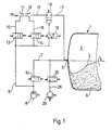
- FIG. 1 shows a rotatably mounted press container, which is divided into a pressure chamber 3 and a press chamber 4 by a flexible membrane 2.
- the pressure chamber 3 is provided with an inlet arrangement 5 for the pressure medium and the press chamber 4 has an outlet arrangement 6 for the pressed-out liquid.
- the pressure chamber 3 is connected to a compressor 8 via a compressed air main line 7. At the compressed air main line 7 there is a pressure after the compressor 8 Air control line 9 connected and then followed by a shut-off device 10. The pressure medium enters the pressure chamber 3 via a rotary inlet, which is not shown in detail.
- the compressed air control line 9 which opens into the pressure chamber 3
- two jet pumps 11 and 12 are arranged, of which one 11 is intended for filling and the other 12 for emptying the pressure chamber.
- the compressed air line 9 is divided into parallel line sections 15 and 16 assigned to each jet pump, which are provided with mutually interacting shut-off valves 13 and 14.
- the jet pumps 11 and 12 are assembled in such a way that their outlet pipes communicate.
- the jet pump 11 intended for filling the pressure chamber 3 is arranged closer to the compressor 8 in the control line 9. Due to its design, which will be explained in more detail in connection with FIG. 2, this jet pump 11 draws in air from the environment and thus generates a larger amount of air, which is intended for filling the pressure chamber.
- the jet pump 12 is provided for emptying a certain amount of residual air from the pressure chamber 3. It is closer to the pressure chamber 3 than the jet pump 11 intended for filling.
- the filling or emptying line 17 has a shut-off element 18, which is kept open when the jet pumps 11, 12 are operated.
- This shut-off element 18 can be actuated via the compressed air control line by means of an actuatable directional valve 19.
- the rotary inlet consisting of the compressed air main line 7 is used.
- a blower 20 is connected to the compressed air main line 7 when a vacuum is generated in the pressure chamber 3 in the filling or mash loosening phases.
- the line connection between the compressed air main line 7 and the blower 20 can, if necessary, i.e. be closed when filling the pressure chamber 3.
- the jet pump 11 used to fill the pressure chamber 3 is connected to the line section 15 of the compressed air control line 9.
- the compressed air enters an annular distributor 21 and flows from there via an annular nozzle 22, in which it is deflected, through the outlet pipe 23 in the direction of the pressure chamber 3. In this process, a vacuum zone is created at the annular nozzle 22, through which ambient air is sucked in and through the outlet pipe 23 is transported into the pressure chamber 3.
- the jet pump 12 connected to line section 16 of the compressed air control line 9 is operated with compressed air from the compressor 8, while the jet pump 11 remains motionless with no compressed air supply.
- a residual air quantity remaining in the pressure chamber 3 after the pressure chamber 3 has been blown off is sucked off by means of the jet pump 12.
- the jet pump 11 is switched off and the shut-off element 18 is closed.
- the shut-off element is closed automatically by means of an energy store, e.g. a spring, while opening takes place by means of a directional control valve 19 connected to the compressed air control line 9.
- the jet pumps 11 and 12 are on the one hand with the shut-off element 18, e.g. Ball valve, and the compressed air control line 9 tightly connected. There are no special precautions for assembly. Item 24 indicates the connection of the compressed air required to operate the ball valve.
- the pressing cycle begins after pre-juicing, i.e. Shut-off device 10 is closed, the compressed air from the compressor 8 flows through the compressed-air control line 9 through the open shut-off valve 13 - shut-off valve 14 is closed - into the jet pump 11.
- the latter sucks in air from the environment, which mixes with the compressor air flows through the shut-off element 18 opened by the actuated directional valve 19 in the filling or emptying line 17 and penetrates into the pressure chamber 3 of the press container 1.
- the membrane 2 detaches from the container wall and lies against the mash.
- the press cycle approximately 33% of the air volume that is required for pressing with a pressure of approximately 2 bar is applied.
- pre-filled compressor air about 20% of the required pre-filling volume is contributed by means of a jet pump for this pre-filling of the pressure chamber.
- blower 20 could be used to support this filling process, acting in the opposite direction from that provided - be it by changing the direction of rotation or changing the line routing.
- shut-off element 18 and possibly slide valve 25 are closed on a signal from the pressure chamber, as is shut-off valve 13 and 14, which is already closed.
- the compressed compressor air now flows through the shut-off device 10, which has now been opened, into the pressure chamber 3 and initiates the pressing out of the mash by building up pressure.
- the pressure chamber is relaxed again by blowing off the compressed air.
- the air flows through the blower 20 by opening the slide valve 25.
- shut-off element 18 could also be opened, so that the air can flow out of the pressure chamber 3 through the jet pump 11 to the environment.
- shut-off device 10 and shut-off valve 13 close, whereas shut-off valve 14 and shut-off element 18 - the latter using the directional control valve 19 - open.
- the compressed air from the compressor now reaches jet pump 12, which sucks the remaining air volume from the pressure chamber 3 and releases it to the environment.
- the blower 20 is also used for this purpose and, after reaching a certain negative pressure in the pressure chamber 3, the jet pump 12 is switched off and the shut-off valve 14 and shut-off element 18 are closed.
- a certain negative pressure value then initiates the loosening phase during which the press container is rotated.
Landscapes
- Engineering & Computer Science (AREA)
- Chemical & Material Sciences (AREA)
- Organic Chemistry (AREA)
- Mechanical Engineering (AREA)
- Health & Medical Sciences (AREA)
- Bioinformatics & Cheminformatics (AREA)
- Physics & Mathematics (AREA)
- Food Science & Technology (AREA)
- Chemical Kinetics & Catalysis (AREA)
- Life Sciences & Earth Sciences (AREA)
- Biochemistry (AREA)
- Fluid Mechanics (AREA)
- General Engineering & Computer Science (AREA)
- General Health & Medical Sciences (AREA)
- Genetics & Genomics (AREA)
- Wood Science & Technology (AREA)
- Zoology (AREA)
- Filling Or Discharging Of Gas Storage Vessels (AREA)
- Reciprocating Pumps (AREA)
Priority Applications (1)
| Application Number | Priority Date | Filing Date | Title |
|---|---|---|---|
| AT83113036T ATE36467T1 (de) | 1983-03-31 | 1983-12-23 | Verfahren und vorrichtung zur beschleunigung des luftaustausches beim fuellen und entleeren eines druckraumes. |
Applications Claiming Priority (2)
| Application Number | Priority Date | Filing Date | Title |
|---|---|---|---|
| CH1803/83 | 1983-03-31 | ||
| CH1803/83A CH655862A5 (de) | 1983-03-31 | 1983-03-31 | Verfahren zur beschleunigung des luftaustausches beim befuellen oder entleeren eines druckraumes und vorrichtung zur durchfuehrung desselben. |
Publications (3)
| Publication Number | Publication Date |
|---|---|
| EP0121001A2 true EP0121001A2 (fr) | 1984-10-10 |
| EP0121001A3 EP0121001A3 (en) | 1986-04-16 |
| EP0121001B1 EP0121001B1 (fr) | 1988-08-17 |
Family
ID=4218962
Family Applications (1)
| Application Number | Title | Priority Date | Filing Date |
|---|---|---|---|
| EP83113036A Expired EP0121001B1 (fr) | 1983-03-31 | 1983-12-23 | Procédé et appareil pour accélérer l'échange de l'air pendant le remplissage ou le déchargement d'une enceinte sous pression |
Country Status (5)
| Country | Link |
|---|---|
| US (1) | US4679601A (fr) |
| EP (1) | EP0121001B1 (fr) |
| AT (1) | ATE36467T1 (fr) |
| CH (1) | CH655862A5 (fr) |
| DE (1) | DE3377698D1 (fr) |
Cited By (1)
| Publication number | Priority date | Publication date | Assignee | Title |
|---|---|---|---|---|
| DE19932403A1 (de) * | 1999-07-14 | 2001-01-18 | Arnold Boroske | Autoklavenanlage und Verfahren zur Autoklavenevakuierung |
Families Citing this family (2)
| Publication number | Priority date | Publication date | Assignee | Title |
|---|---|---|---|---|
| DE59405290D1 (de) * | 1993-06-29 | 1998-04-02 | Bucher Guyer Ag Masch | Verfahren und Einrichtung zur Beschleunigung des Austausches von Luft oder Gas als Druckmedium |
| IT1302199B1 (it) * | 1998-09-11 | 2000-07-31 | Siprem Internat S R L | Apparecchiatura perfezionata per la separazione di sostanze liquidee solide, in particolare per l'estrazione di succo dalla frutta e |
Citations (4)
| Publication number | Priority date | Publication date | Assignee | Title |
|---|---|---|---|---|
| GB468667A (en) * | 1935-11-23 | 1937-07-09 | D F Ets | Method of supplying air under pressure and applying suction on board aircraft and apparatus therefor |
| US3606586A (en) * | 1969-07-14 | 1971-09-20 | Futurecraft Corp | Air injection pump |
| US3734122A (en) * | 1972-02-14 | 1973-05-22 | Sybron Corp | Dental compressed air/vacuum apparatus |
| FR2289124A1 (fr) * | 1974-10-31 | 1976-05-28 | Willmes Josef Kg | Recipient a decantation de liquide et pressurage |
Family Cites Families (15)
| Publication number | Priority date | Publication date | Assignee | Title |
|---|---|---|---|---|
| US2721694A (en) * | 1954-01-29 | 1955-10-25 | New York Air Brake Co | First stage mechanical pump for use in a two stage vacuum pumping system |
| US2724508A (en) * | 1954-05-26 | 1955-11-22 | Sun Oil Co | Separator for solid-liquid slurry |
| US3150594A (en) * | 1960-02-01 | 1964-09-29 | Kobe Inc | High speed triplex pump |
| US3111260A (en) * | 1960-07-09 | 1963-11-19 | N G N Ltd | Rotary pumps |
| US3447467A (en) * | 1967-05-05 | 1969-06-03 | Jerry Heinige | Ejection pump |
| US3624729A (en) * | 1968-01-29 | 1971-11-30 | Maurice W Hoover | Continuous juice extractor |
| US3642384A (en) * | 1969-11-19 | 1972-02-15 | Henry Huse | Multistage vacuum pumping system |
| US3719196A (en) * | 1970-05-06 | 1973-03-06 | Jones R Mc | Charging sequence system and process |
| US3875745A (en) * | 1973-09-10 | 1975-04-08 | Wagner Minning Equipment Inc | Venturi exhaust cooler |
| CH604841A5 (fr) * | 1975-12-22 | 1978-09-15 | Bucher Guyer Ag Masch | |
| CH605109A5 (fr) * | 1976-04-21 | 1978-09-29 | Bucher Guyer Ag Masch | |
| US4107404A (en) * | 1977-01-31 | 1978-08-15 | The United States Of America As Represented By The Secretary Of The Army | Stabilization of LiAsF6 /dimethyl sulfite electrolyte solution |
| US4309151A (en) * | 1979-05-03 | 1982-01-05 | Lucas Industries Limited | Liquid fuel injection pumping apparatus |
| DE3108247A1 (de) * | 1981-03-05 | 1982-09-16 | Robert Bosch Gmbh, 7000 Stuttgart | Reifendruckregelanlage |
| US4422830A (en) * | 1981-12-14 | 1983-12-27 | Atlantic Richfield Company | Performance of a pipeline additive injection system |
-
1983
- 1983-03-31 CH CH1803/83A patent/CH655862A5/de not_active IP Right Cessation
- 1983-12-23 EP EP83113036A patent/EP0121001B1/fr not_active Expired
- 1983-12-23 DE DE8383113036T patent/DE3377698D1/de not_active Expired
- 1983-12-23 AT AT83113036T patent/ATE36467T1/de not_active IP Right Cessation
-
1986
- 1986-04-02 US US06/847,164 patent/US4679601A/en not_active Expired - Lifetime
Patent Citations (4)
| Publication number | Priority date | Publication date | Assignee | Title |
|---|---|---|---|---|
| GB468667A (en) * | 1935-11-23 | 1937-07-09 | D F Ets | Method of supplying air under pressure and applying suction on board aircraft and apparatus therefor |
| US3606586A (en) * | 1969-07-14 | 1971-09-20 | Futurecraft Corp | Air injection pump |
| US3734122A (en) * | 1972-02-14 | 1973-05-22 | Sybron Corp | Dental compressed air/vacuum apparatus |
| FR2289124A1 (fr) * | 1974-10-31 | 1976-05-28 | Willmes Josef Kg | Recipient a decantation de liquide et pressurage |
Cited By (2)
| Publication number | Priority date | Publication date | Assignee | Title |
|---|---|---|---|---|
| DE19932403A1 (de) * | 1999-07-14 | 2001-01-18 | Arnold Boroske | Autoklavenanlage und Verfahren zur Autoklavenevakuierung |
| DE19932403B4 (de) * | 1999-07-14 | 2008-09-18 | Arnold Boroske | Verfahren zur Autoklavenevakuierung zur Porenbetonkörper- oder Kalksandsteinherstellung, Autoklavenanlage dazu sowie Verwendung einer Injektorstrahlpumpe |
Also Published As
| Publication number | Publication date |
|---|---|
| CH655862A5 (de) | 1986-05-30 |
| US4679601A (en) | 1987-07-14 |
| EP0121001A3 (en) | 1986-04-16 |
| DE3377698D1 (en) | 1988-09-22 |
| ATE36467T1 (de) | 1988-09-15 |
| EP0121001B1 (fr) | 1988-08-17 |
Similar Documents
| Publication | Publication Date | Title |
|---|---|---|
| DE102007045330A1 (de) | Beschichtungspulver-Förderverfahren, Beschichtungspulver-Fördervorrichtung und elektrostatische Pulversprühbeschichtungsvorrichtung | |
| DE1519988C3 (de) | Vorrichtung zum Fraktionieren von Gasgemischen | |
| DE69226329T2 (de) | Verfahren zum Fördern von Fluidum mittels Druckluft | |
| EP0121001B1 (fr) | Procédé et appareil pour accélérer l'échange de l'air pendant le remplissage ou le déchargement d'une enceinte sous pression | |
| DE3133032C2 (fr) | ||
| EP0003593B1 (fr) | Procédé et appareil pour la filtration d'une boue ou matière analogue dans un filtre-presse | |
| DE69829546T2 (de) | Pumpsystem für Flüssigkeiten | |
| DE2244917C3 (de) | Verfahren und Vorrichtung zum Beschicken einer Filtervorrichtung | |
| EP3192406B1 (fr) | Actionneur hydraulique pour un appareil de préparation de boissons chaudes | |
| DE2404722A1 (de) | Im time-sharing arbeitende verdichtungsvorrichtung | |
| DE3502999C2 (de) | Vorrichtung zur Restentleerung des Tankraums eines Flüssigkeitstanks | |
| DE664566C (de) | Verfahren zur stufenlosen Mengenregelung von ein- oder mehrstufigen Kolbenverdichtern unter Verwendung eines unveraenderlichen Zuschaltraumes | |
| DE638296C (de) | Fluessigkeitsfoerdervorrichtung, bei welcher als Foerdermittel Druckgas verwendet wird | |
| AT405487B (de) | Verfahren und vorrichtung zum austragen von feucht/rieselfähigem bis pastösem material aus einem druckfilter | |
| DE4323711A1 (de) | Druckmittelbetätigte Presse zum Auspressen von Flüssigkeit enthaltenden Stoffen | |
| WO2018158345A1 (fr) | Dispositif et procédé servant à séparer un lubrifiant d'un flux de gaz, ainsi qu'installation et procédé servant à la compression de gaz inflammables | |
| DE2263184C3 (de) | Gasturbinenanlage mit unterirdischem Luftspeicher | |
| DE3432456C2 (de) | Pumpe zum Fördern eines flüssigen oder zähflüssigen Mediums | |
| DE3543030C2 (fr) | ||
| DE827506C (de) | Einrichtung an Druckzylindern, insbesondere Pressluftzylindern fuer Druckluftbremsen | |
| DE2932820A1 (de) | Verfahren und vorrichtung zur internen druckbeaufschlagung eines geschlossenen raumes, insbesondere zu pruefzwecken | |
| DE701864C (de) | Verfahren zum Entspannen eines Gemisches von fluessigen mit gasfoermigen und gegebenefalls festen Stoffen aus unter hohem Druck stehenden Gefaessen | |
| WO2021097505A1 (fr) | Compresseur | |
| DE24485C (de) | Bierdruckapparat | |
| AT220071B (fr) |
Legal Events
| Date | Code | Title | Description |
|---|---|---|---|
| PUAI | Public reference made under article 153(3) epc to a published international application that has entered the european phase |
Free format text: ORIGINAL CODE: 0009012 |
|
| 17P | Request for examination filed |
Effective date: 19831223 |
|
| AK | Designated contracting states |
Kind code of ref document: A2 Designated state(s): AT DE FR IT Designated state(s): AT DE FR IT |
|
| PUAL | Search report despatched |
Free format text: ORIGINAL CODE: 0009013 |
|
| AK | Designated contracting states |
Kind code of ref document: A3 Designated state(s): AT DE FR IT |
|
| 17Q | First examination report despatched |
Effective date: 19870703 |
|
| ITF | It: translation for a ep patent filed | ||
| GRAA | (expected) grant |
Free format text: ORIGINAL CODE: 0009210 |
|
| AK | Designated contracting states |
Kind code of ref document: B1 Designated state(s): AT DE FR IT |
|
| REF | Corresponds to: |
Ref document number: 36467 Country of ref document: AT Date of ref document: 19880915 Kind code of ref document: T |
|
| REF | Corresponds to: |
Ref document number: 3377698 Country of ref document: DE Date of ref document: 19880922 |
|
| ET | Fr: translation filed | ||
| PLBE | No opposition filed within time limit |
Free format text: ORIGINAL CODE: 0009261 |
|
| STAA | Information on the status of an ep patent application or granted ep patent |
Free format text: STATUS: NO OPPOSITION FILED WITHIN TIME LIMIT |
|
| 26N | No opposition filed | ||
| ITTA | It: last paid annual fee | ||
| PGFP | Annual fee paid to national office [announced via postgrant information from national office to epo] |
Ref country code: AT Payment date: 20021204 Year of fee payment: 20 |
|
| PGFP | Annual fee paid to national office [announced via postgrant information from national office to epo] |
Ref country code: FR Payment date: 20021206 Year of fee payment: 20 |
|
| PGFP | Annual fee paid to national office [announced via postgrant information from national office to epo] |
Ref country code: DE Payment date: 20021218 Year of fee payment: 20 |
|
| PG25 | Lapsed in a contracting state [announced via postgrant information from national office to epo] |
Ref country code: AT Free format text: LAPSE BECAUSE OF EXPIRATION OF PROTECTION Effective date: 20031223 |