EP0121001A2 - Process and apparatus for accelerating the exchange of air during the filling or emptying of a pressurized space - Google Patents
Process and apparatus for accelerating the exchange of air during the filling or emptying of a pressurized space Download PDFInfo
- Publication number
- EP0121001A2 EP0121001A2 EP83113036A EP83113036A EP0121001A2 EP 0121001 A2 EP0121001 A2 EP 0121001A2 EP 83113036 A EP83113036 A EP 83113036A EP 83113036 A EP83113036 A EP 83113036A EP 0121001 A2 EP0121001 A2 EP 0121001A2
- Authority
- EP
- European Patent Office
- Prior art keywords
- pressure chamber
- compressed air
- filling
- shut
- line
- Prior art date
- Legal status (The legal status is an assumption and is not a legal conclusion. Google has not performed a legal analysis and makes no representation as to the accuracy of the status listed.)
- Granted
Links
Images

Classifications
-
- C—CHEMISTRY; METALLURGY
- C12—BIOCHEMISTRY; BEER; SPIRITS; WINE; VINEGAR; MICROBIOLOGY; ENZYMOLOGY; MUTATION OR GENETIC ENGINEERING
- C12C—BEER; PREPARATION OF BEER BY FERMENTATION; PREPARATION OF MALT FOR MAKING BEER; PREPARATION OF HOPS FOR MAKING BEER
- C12C7/00—Preparation of wort
- C12C7/04—Preparation or treatment of the mash
-
- B—PERFORMING OPERATIONS; TRANSPORTING
- B01—PHYSICAL OR CHEMICAL PROCESSES OR APPARATUS IN GENERAL
- B01J—CHEMICAL OR PHYSICAL PROCESSES, e.g. CATALYSIS OR COLLOID CHEMISTRY; THEIR RELEVANT APPARATUS
- B01J3/00—Processes of utilising sub-atmospheric or super-atmospheric pressure to effect chemical or physical change of matter; Apparatus therefor
- B01J3/002—Component parts of these vessels not mentioned in B01J3/004, B01J3/006, B01J3/02 - B01J3/08; Measures taken in conjunction with the process to be carried out, e.g. safety measures
-
- B—PERFORMING OPERATIONS; TRANSPORTING
- B30—PRESSES
- B30B—PRESSES IN GENERAL
- B30B9/00—Presses specially adapted for particular purposes
- B30B9/02—Presses specially adapted for particular purposes for squeezing-out liquid from liquid-containing material, e.g. juice from fruits, oil from oil-containing material
- B30B9/04—Presses specially adapted for particular purposes for squeezing-out liquid from liquid-containing material, e.g. juice from fruits, oil from oil-containing material using press rams
- B30B9/047—Control arrangements
-
- B—PERFORMING OPERATIONS; TRANSPORTING
- B30—PRESSES
- B30B—PRESSES IN GENERAL
- B30B9/00—Presses specially adapted for particular purposes
- B30B9/02—Presses specially adapted for particular purposes for squeezing-out liquid from liquid-containing material, e.g. juice from fruits, oil from oil-containing material
- B30B9/22—Presses specially adapted for particular purposes for squeezing-out liquid from liquid-containing material, e.g. juice from fruits, oil from oil-containing material using a flexible member, e.g. diaphragm, urged by fluid pressure
Definitions
- the invention relates to a method for accelerating the exchange of air or gas and for saving operating energy when filling and / or emptying a pressure chamber.
- Such a pressure chamber can serve to store compressed air and gases as well as be used for the separation of liquid and solid substances.
- a pressure chamber which is divided into a pressure chamber and a press chamber by a flexible membrane and in which the pressure chamber is an inlet arrangement for the pressure medium and the press chamber is an outlet arrangement for the one to be pressed out
- the pressure chamber is filled with compressed air from a compressor until the pressure is reached.
- the object of the invention is therefore to provide a method for accelerating the air exchange and for saving operating energy for filling and emptying pressure chambers in order to be able to improve the economic consequences.
- this object is achieved in that the pressure chamber is filled in a first stage or emptied by means of a jet pump which is connected to the pressure chamber.
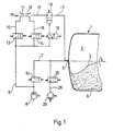
- FIG. 1 shows a rotatably mounted press container, which is divided into a pressure chamber 3 and a press chamber 4 by a flexible membrane 2.
- the pressure chamber 3 is provided with an inlet arrangement 5 for the pressure medium and the press chamber 4 has an outlet arrangement 6 for the pressed-out liquid.
- the pressure chamber 3 is connected to a compressor 8 via a compressed air main line 7. At the compressed air main line 7 there is a pressure after the compressor 8 Air control line 9 connected and then followed by a shut-off device 10. The pressure medium enters the pressure chamber 3 via a rotary inlet, which is not shown in detail.
- the compressed air control line 9 which opens into the pressure chamber 3
- two jet pumps 11 and 12 are arranged, of which one 11 is intended for filling and the other 12 for emptying the pressure chamber.
- the compressed air line 9 is divided into parallel line sections 15 and 16 assigned to each jet pump, which are provided with mutually interacting shut-off valves 13 and 14.
- the jet pumps 11 and 12 are assembled in such a way that their outlet pipes communicate.
- the jet pump 11 intended for filling the pressure chamber 3 is arranged closer to the compressor 8 in the control line 9. Due to its design, which will be explained in more detail in connection with FIG. 2, this jet pump 11 draws in air from the environment and thus generates a larger amount of air, which is intended for filling the pressure chamber.
- the jet pump 12 is provided for emptying a certain amount of residual air from the pressure chamber 3. It is closer to the pressure chamber 3 than the jet pump 11 intended for filling.
- the filling or emptying line 17 has a shut-off element 18, which is kept open when the jet pumps 11, 12 are operated.
- This shut-off element 18 can be actuated via the compressed air control line by means of an actuatable directional valve 19.
- the rotary inlet consisting of the compressed air main line 7 is used.
- a blower 20 is connected to the compressed air main line 7 when a vacuum is generated in the pressure chamber 3 in the filling or mash loosening phases.
- the line connection between the compressed air main line 7 and the blower 20 can, if necessary, i.e. be closed when filling the pressure chamber 3.
- the jet pump 11 used to fill the pressure chamber 3 is connected to the line section 15 of the compressed air control line 9.
- the compressed air enters an annular distributor 21 and flows from there via an annular nozzle 22, in which it is deflected, through the outlet pipe 23 in the direction of the pressure chamber 3. In this process, a vacuum zone is created at the annular nozzle 22, through which ambient air is sucked in and through the outlet pipe 23 is transported into the pressure chamber 3.
- the jet pump 12 connected to line section 16 of the compressed air control line 9 is operated with compressed air from the compressor 8, while the jet pump 11 remains motionless with no compressed air supply.
- a residual air quantity remaining in the pressure chamber 3 after the pressure chamber 3 has been blown off is sucked off by means of the jet pump 12.
- the jet pump 11 is switched off and the shut-off element 18 is closed.
- the shut-off element is closed automatically by means of an energy store, e.g. a spring, while opening takes place by means of a directional control valve 19 connected to the compressed air control line 9.
- the jet pumps 11 and 12 are on the one hand with the shut-off element 18, e.g. Ball valve, and the compressed air control line 9 tightly connected. There are no special precautions for assembly. Item 24 indicates the connection of the compressed air required to operate the ball valve.
- the pressing cycle begins after pre-juicing, i.e. Shut-off device 10 is closed, the compressed air from the compressor 8 flows through the compressed-air control line 9 through the open shut-off valve 13 - shut-off valve 14 is closed - into the jet pump 11.
- the latter sucks in air from the environment, which mixes with the compressor air flows through the shut-off element 18 opened by the actuated directional valve 19 in the filling or emptying line 17 and penetrates into the pressure chamber 3 of the press container 1.
- the membrane 2 detaches from the container wall and lies against the mash.
- the press cycle approximately 33% of the air volume that is required for pressing with a pressure of approximately 2 bar is applied.
- pre-filled compressor air about 20% of the required pre-filling volume is contributed by means of a jet pump for this pre-filling of the pressure chamber.
- blower 20 could be used to support this filling process, acting in the opposite direction from that provided - be it by changing the direction of rotation or changing the line routing.
- shut-off element 18 and possibly slide valve 25 are closed on a signal from the pressure chamber, as is shut-off valve 13 and 14, which is already closed.
- the compressed compressor air now flows through the shut-off device 10, which has now been opened, into the pressure chamber 3 and initiates the pressing out of the mash by building up pressure.
- the pressure chamber is relaxed again by blowing off the compressed air.
- the air flows through the blower 20 by opening the slide valve 25.
- shut-off element 18 could also be opened, so that the air can flow out of the pressure chamber 3 through the jet pump 11 to the environment.
- shut-off device 10 and shut-off valve 13 close, whereas shut-off valve 14 and shut-off element 18 - the latter using the directional control valve 19 - open.
- the compressed air from the compressor now reaches jet pump 12, which sucks the remaining air volume from the pressure chamber 3 and releases it to the environment.
- the blower 20 is also used for this purpose and, after reaching a certain negative pressure in the pressure chamber 3, the jet pump 12 is switched off and the shut-off valve 14 and shut-off element 18 are closed.
- a certain negative pressure value then initiates the loosening phase during which the press container is rotated.
Abstract
Description
Die Erfindung betrifft ein Verfahren zur Beschleunigung des Luft- bzw. Gasaustausches und zur Einsparung von Betriebsenergie beim Befüllen und/oder Entleeren eines Druckraumes.The invention relates to a method for accelerating the exchange of air or gas and for saving operating energy when filling and / or emptying a pressure chamber.
Bei einem derartigen Verfahren fallen einerseits beim Befüllen des Druckraumes in der Anfangsphase bis zum Erreichen eines geringen Druckes über dem Umgebungsdruck unwirtschaftliche Energiekosten an, weil die in einem Kompressor auf einen höheren Druck aufbereitete Luft oder ein Gas auf dem Transportweg in den leeren Druckraum wieder expandiert. Alternativ erfordert der Einsatz eines Gebläses zum gleichen Zweck weniger Energie, hingegen wird zum Erreichen eines minimalen Füllgrades bei erheblich geringerem Füllvermögen eine grössere Einsatzzeit benötigt, die sich nachteilig auf die Effizienz beim Befüllen des Druckraumes auswirkt.In such a method, on the one hand, when the pressure chamber is filled in the initial phase until a low pressure is reached above the ambient pressure, uneconomical energy costs are incurred because the air or a gas prepared for a higher pressure in a compressor expands again into the empty pressure chamber during transport. Alternatively, the use of a blower for the same purpose requires less energy, on the other hand, in order to achieve a minimum filling level with a significantly lower filling capacity, a longer operating time is required, which has a disadvantageous effect on the efficiency when filling the pressure chamber.
Aehnlich verhält es sich beim Entleeren eines Druckraumes mit anschliessendem Aufbau eines Vakuums. Hier wird beim Oeffnen eines Ventils relativ schnell eine Entspannung der Druckspitze erreicht, währenddem die Entspannung des Druckes über dem Umgebungsdruck und der anschliessende Aufbau eines Vakuums sich nur mit relativ hohem Energieaufwand bzw. bei Verwendung eines Gebläses mit einer erheblichen Verlängerung der Prozesszeit bewerkstelligen lässt.The situation is similar when emptying a pressure chamber and then building up a vacuum. Here, when the valve is opened, the pressure peak is released relatively quickly, while the relaxation of the pressure above the ambient pressure and the subsequent build-up of a vacuum can only be achieved with a relatively high expenditure of energy or, if a blower is used, with a considerable increase in the process time.
Ein solcher Druckraum kann sowohl der Speicherung komprimierter Luft und Gase dienen als auch beim Trennen von flüssigen und festen Stoffen verwendet werden. So sind beispielsweise bei Einrichtungen zum Trennen von festen und flüssigen Stoffen mit einem drehbar gelagerten Pressbehälter, der durch eine flexible Membran in einen Druckraum und in einen Pressraum unterteilt ist und bei dem der Druckraum eine Einlassanordnung für das Druckmedium und der Pressraum eine Auslassanordnung für die auszupressende Flüssigkeit aufweist, bekannt, deren Druckraum bis zum Erreichen des Pressdruckes mit Druckluft aus einem Kompressor aufgefüllt wird.Such a pressure chamber can serve to store compressed air and gases as well as be used for the separation of liquid and solid substances. For example, in devices for separating solid and liquid substances with a rotatably mounted press container which is divided into a pressure chamber and a press chamber by a flexible membrane and in which the pressure chamber is an inlet arrangement for the pressure medium and the press chamber is an outlet arrangement for the one to be pressed out Has liquid, known, the pressure chamber is filled with compressed air from a compressor until the pressure is reached.
Erfahrungsgemäss ist zum Auspressen der Maische bei einer solchen Einrichtung ein Drittel des in den Druckraum einzuführenden Luftvolumens dazu notwendig, die unter Vakuum an der Behälterwand anliegende Membran an die Maische anzulegen.Experience has shown that, in order to squeeze out the mash in such a device, a third of the air volume to be introduced into the pressure chamber is necessary to apply the membrane resting on the container wall under vacuum to the mash.
Das Aufbereiten von Luft mittels Kompressor, zum Zwekke des Anlegens der Membran an die Maische ist nicht effizient genug und es ist ebenso unbefriedigend, nach dem Abblasen des Druckraumes die Restluft mittels Gebläse abzusaugen.The preparation of air by means of a compressor for the purpose of applying the membrane to the mash is not efficient enough and it is also unsatisfactory to extract the residual air by means of a fan after the pressure chamber has been blown off.
Gleiches gilt beim Befüllen bzw. Entleeren eines Druckraumes zur Speicherung von Gasen oder Luft.The same applies when filling or emptying a pressure chamber for storing gases or air.
Auf Wunsch können diese Anlagen mit einem zusätzlichen Gebläse versehen werden, das die Aufgabe des Anlegens der Membran an die Maische übernimmt; diesbezüglich sind solche Anwendungen in der Praxis bekannt. Somit ist es möglich, den Vordruck und das Absaugen der Luft im Druckraum unter geringerem Energieaufwand als bisher zu erreichen. Als Nachteil bleibt die längere Betriebszeit, die sich aufgrund mehrerer Arbeitszyklen entsprechend erhöht.On request, these systems can be equipped with an additional blower, which takes on the task of placing the membrane on the mash; In this regard, such applications are known in practice. It is thus possible to achieve the pre-pressure and the suction of the air in the pressure chamber with less energy expenditure than before. The disadvantage is the longer operating time, which increases accordingly due to several working cycles.
Aufgabe der Erfindung ist es somit, für das Befüllen und Entleeren von Druckräumen ein Verfahren zur Beschleunigung des Luftaustausches und zur Einsparung von Betriebsenergie zu schaffen, um die wirtschaftlichen Konsequenzen verbessern zu können.The object of the invention is therefore to provide a method for accelerating the air exchange and for saving operating energy for filling and emptying pressure chambers in order to be able to improve the economic consequences.
Erfindungsgemäss wird diese Aufgabe dadurch gelöst, dass das Befüllen des Druckraumes in einer ersten Stufe bzw. das Entleeren mittels einer mit dem Druckraum leitungsverbundenen, Strahlpumpe erfolgt.According to the invention, this object is achieved in that the pressure chamber is filled in a first stage or emptied by means of a jet pump which is connected to the pressure chamber.
Weitere Merkmale, Einzelheiten und Vorteile der Erfindung sind der Beschreibung und Zeichnung zu entnehmen. Es zeigen:
- Fig. l eine schematische Darstellung der erfindungsgemässen Einrichtung und
- Fig. 2 einen Längsschnitt durch die Strahlpumpenvorrichtung.
- 1 shows a schematic representation of the device according to the invention and
- Fig. 2 shows a longitudinal section through the jet pump device.
In Fig. l ist gemäss Pos.l ein drehbar gelagerter Pressbehälter veranschaulicht, der durch eine flexible Membran 2 in einen Druckraum 3 und in einen Pressraum 4 unterteilt ist. Der Druckraum 3 ist mit einer Einlassanordnung 5 für das Druckmedium versehen und der Pressraum 4 weist eine Auslassanordnung 6 für die ausgepresste Flüssigkeit auf.1 shows a rotatably mounted press container, which is divided into a
Der Druckraum 3 ist über eine Druckluft-Hauptleitung 7 mit einem Kompressor 8 verbunden. An der Druckluft-Hauptleitung 7 ist nach dem Kompressor 8 eine Druckluft-Steuerleitung 9 angeschlossen und anschliessend folgt ein Absperrorgan 10. Der Zutritt des Druckmediums in den Druckraum 3 erfolgt über eine Dreheinführung, die nicht näher dargestellt ist.The
In der Druckluft-Steuerleitung 9, die in den Druckraum 3 mündet, sind zwei Strahlpumpen 11 und 12 angeordnet, von denen die eine 11 zum Befüllen und die andere 12 zum Entleeren des Druckraumes bestimmt ist. Zum wechselweisen Betrieb dieser Strahlpumpen 11,12 ist die Druckluftleitung 9 in jeweils jeder Strahlpumpe zugeordnete, parallele Leitungsabschnitte 15 und 16 aufgeteilt, die mit wechselweise zusammenwirkenden Absperrventilen 13 und 14 versehen sind. Die Strahlpumpen 11 und 12 sind derart zusammengebaut, dass ihre Auslassrohre kommunizieren. Zur Erzielung eines optimalen Wirkungsgrades ist die zum Befüllen des Druckraumes 3 bestimmte Strahlpumpe 11 dem Kompressor 8 in der Steuerleitung 9 näher angeordnet. Diese Strahlpumpe 11 saugt aufgrund ihrer Ausbildung, die noch im Zusammenhang mit Fig.2 näher zu erläutern sein wird, Luft aus der Umgebung an und erzeugt damit eine grössere Luftmenge, die zum Befüllen des Druckraumes bestimmt ist.In the compressed air control line 9, which opens into the
Die Strahlpumpe 12 ist zum Entleeren einer bestimmten Restluftmenge aus dem Druckraum 3 vorgesehen. Sie liegt näher beim Druckraum 3 als die zum Befüllen bestimmte Strahlpumpe 11.The
Die Füll- bzw. Entleerungsleitung 17 weist ein Absperrelement 18 auf, welches bei betriebenen Strahlpumpen 11,12 offen gehalten wird. Die Betätigung dieses Absperrelementes 18 kann über die Druckluft-Steuerleitung mittels betätigbarem Wegeventil 19 erfolgen.The filling or emptying
Zur Verbindung der Füll- bzw. Entleerungsleitung 17 mit dem Druckraum 3 wird die von der Druckluft-Hauptleitung 7 bestehende Dreheinführung verwendet. Zur weiteren Senkung der Betriebskosten ist bei der Erzeugung eines Vakuums im Druckraum 3 in der Füll-oder den Maischeauflockerungsphasen ein Gebläse 20 an die Druckluft-Hauptleitung 7 angeschlossen. Die Leitungsverbindung zwischen Druckluft-Hauptleitung 7 und Gebläse 20 kann im Bedarfsfalle, d.h. beim Füllen des Druckraumes 3 geschlossen werden.To connect the filling or emptying
In Fig.2 ist die praxisnahe Ausbildung der Strahlpumpen 11,12 dargestellt, wie sie zusammen mit dem Absperrelment 18 am Pressbehälter 1 angeordnet sind. Die zum Befüllen des Druckraumes 3 verwendete Strahlpumpe 11 ist an den Leitungsabschnitt 15 der Druckluft-Steuerleitung 9 angeschlossen. Die Druckluft tritt in einen ringförmigen Verteiler 21 ein und strömt von dort über eine Ringdüse 22, in der sie umgelenkt wird, durch das Auslassrohr 23 in Richtung Druckraum 3. Bei diesem Vorgang entsteht an der Ringdüse 22 eine Unterdruckzone, durch die Umgebungsluft angesaugt und durch das Auslassrohr 23 in den Druckraum 3 transportiert wird.2 shows the practical design of the
Beim Entleeren des Druckraumes 3 wird die mit Leitungsabschnitt 16 der Druckluft-Steuerleitung 9 verbundene Strahlpumpe 12 mit Druckluft vom Kompressor 8 betrieben, während Strahlpumpe 11 regungslos ohne Druckluftzufuhr bleibt. Mittels Strahlpumpe 12 wird eine im Druckraum 3 nach dem Abblasen des Druckraumes 3 verbleibende Restluftmenge abgesaugt.When the
Wie eingangs erwähnt, wird nach Erreichen eines bestimmten Druckes im Druckraum 3 die Strahlpumpe 11 abgestellt und Absperrelement 18 geschlossen. Das Schliessen des Absperrelementes erfolgt selbsttätig mittels eines Kraftspeichers, z.B. einer Feder, während das Oeffnen mittels eines an der Druckluft-Steuerleitung 9 angeschlossenen Wegeventils 19 geschieht.As mentioned at the beginning, after reaching a certain pressure in the
Die Strahlpumpen 11 und 12 sind einerseits mit dem an Flanschen am Pressbehälter 1 befestigten Absperrelement 18, z.B. Kugelhahn, und der Druckluft-Steuerleitung 9 dicht verbunden. Besondere Vorkehrungen zur Montage sind nicht getroffen. Pos. 24 weist auf den Anschluss der zur Betätigung des Kugelhahns erforderlichen Druckluft hin.The
Funktionsweise bei einer Einrichtung zum Trennen von flüssigen und festen Stoffen mit einer eingangs beschriebenen Presse.Functioning in a device for separating liquid and solid materials with a press described at the beginning.
Ausgehend von der mit Maische gefüllten Presse beginnt nach erfolgter Vorentsaftung der Presszyklus, d.h. Absperrorgan 10 ist geschlossen, die Druckluft aus dem Kompressor 8 strömt durch die Druckluft-Steuerleitung 9 durch das offene Absperrventil 13 - Absperrventil 14 ist geschlossen - in die Strahlpumpe 11. Aus der Umgebung saugt letztere Luft an, die unter Mischwirkung mit der Kompressor-Luft in der Füll- bzw. Entleerungsleitung 17 das durch das betätigte Wegeventil 19 geöffnete Absperrelement 18 durchströmt und in den Druckraum 3 des Pressbehälters 1 dringt. Dabei löst sich die Membran 2 von der Behälterwand und legt sich an der Maische an.Starting from the press filled with mash, the pressing cycle begins after pre-juicing, i.e. Shut-off
Für diesen als erste Stufe bezeichneten Vorgang im Presszyklus werden ca. 33 desjenigen Luftvolumens aufgebracht, das zum Pressen mit ca. 2 bar Druck benötigt wird.For this process, referred to as the first stage, in the press cycle, approximately 33% of the air volume that is required for pressing with a pressure of approximately 2 bar is applied.
An aufbereiteter Kompressor-Luft werden für dieses Vorfüllen des Druckraumes mittels Strahlpumpe ca. 20 % an das benötigte Vorfüllvolumen beigesteuert.In pre-filled compressor air, about 20% of the required pre-filling volume is contributed by means of a jet pump for this pre-filling of the pressure chamber.
Hilfsweise könnte zur Unterstützung dieses Füllvorganges das Gebläse 20 in umgekehrter Richtung wirkend als vorgesehen - sei es durch Drehrichtungsänderung oder Aenderung der Leitungsführung - verwendet werden.In the alternative, the
Bei Erreichen eines bestimmten Druckes im Druckraum wird auf ein Signal aus dem Druckraum das Absperrelement 18 und allenfalls Schieberventil 25 geschlossen, ebenso Absperrventil 13 und 14, welches bereits geschlossen ist. Die komprimierte Kompressor-Luft strömt nun durch das inzwischen geöffnete Absperrorgan 10 in den Druckraum 3 und leitet durch einen Druckaufbau das Auspressen der Maische ein.When a certain pressure in the pressure chamber is reached, the shut-off
Nach einer bestimmten Verweilzeit der Membran unter Pressdruck, wird der Druckraum durch Abblasen der komprimierten Luft wieder entspannt. Die Luft strömt durch Oeffnen des Schieberventils 25 durch das Gebläse 20 ab.After a certain dwell time of the membrane under pressure, the pressure chamber is relaxed again by blowing off the compressed air. The air flows through the
Zur Verkürzung der Abblaszeit könnte auch Absperrelement 18 geöffnet werden, sodass die Luft aus dem Druckraum 3 durch die Strahlpumpe 11 an die Umgebung abströmen kann.To shorten the blow-off time, shut-off
Vor Eintreten von Umgebungsdruck im Druckraum oder bei ca. 0,2 bar Ueberdruck, schliesst Absperrorgan 10 und Absperrventil 13, wogegen Absperrventil 14 und Absperrelement 18 - letzteres mit Hilfe des Wegeventils 19 - öffnen. Die Druckluft aus dem Kompressor erreicht nun Strahlpumpe 12, welche die Restluftmenge aus dem Druckraum 3 saugt und sie an die Umgebung abgibt. Zu diesem Zwecke wird auch das Gebläse 20 eingesetzt und nach Erreichen eines bestimmten Unterdruckes im Druckraum 3 wird Strahlpumpe 12 abgeschaltet und Absperrventil 14 sowie Absperrelement 18 geschlossen.Before the occurrence of ambient pressure in the pressure chamber or at approx. 0.2 bar overpressure, the shut-off
Anschliessend leitet ein bestimmter Unterdruckswert die Auflockerungsphase ein, während welcher der Pressbehälter in Drehung versetzt wird.A certain negative pressure value then initiates the loosening phase during which the press container is rotated.
Diese Arbeitszyklen wiederholen sich sodann mehrmals nach einer programmierten Prozesssteuerung.These working cycles are then repeated several times after a programmed process control.
Es wäre selbstverständlich möglich, das Verfahren ohne besondere Vorkehrungen mit einem flüssigen Druckmedium durchzuführen.It would of course be possible to carry out the process with a liquid pressure medium without special precautions.
Claims (13)
Priority Applications (1)
| Application Number | Priority Date | Filing Date | Title |
|---|---|---|---|
| AT83113036T ATE36467T1 (en) | 1983-03-31 | 1983-12-23 | METHOD AND DEVICE FOR ACCELERATING THE AIR EXCHANGE WHEN FILLING AND EMPTYING A PRESSURE SPACE. |
Applications Claiming Priority (2)
| Application Number | Priority Date | Filing Date | Title |
|---|---|---|---|
| CH1803/83A CH655862A5 (en) | 1983-03-31 | 1983-03-31 | METHOD FOR ACCELERATING THE AIR EXCHANGE WHEN FILLING OR EMPTYING A PRESSURE ROOM AND DEVICE FOR IMPLEMENTING THE SAME. |
| CH1803/83 | 1983-03-31 |
Publications (3)
| Publication Number | Publication Date |
|---|---|
| EP0121001A2 true EP0121001A2 (en) | 1984-10-10 |
| EP0121001A3 EP0121001A3 (en) | 1986-04-16 |
| EP0121001B1 EP0121001B1 (en) | 1988-08-17 |
Family
ID=4218962
Family Applications (1)
| Application Number | Title | Priority Date | Filing Date |
|---|---|---|---|
| EP83113036A Expired EP0121001B1 (en) | 1983-03-31 | 1983-12-23 | Process and apparatus for accelerating the exchange of air during the filling or emptying of a pressurized space |
Country Status (5)
| Country | Link |
|---|---|
| US (1) | US4679601A (en) |
| EP (1) | EP0121001B1 (en) |
| AT (1) | ATE36467T1 (en) |
| CH (1) | CH655862A5 (en) |
| DE (1) | DE3377698D1 (en) |
Cited By (1)
| Publication number | Priority date | Publication date | Assignee | Title |
|---|---|---|---|---|
| DE19932403A1 (en) * | 1999-07-14 | 2001-01-18 | Arnold Boroske | Autoclave plant with pressure-resistant reaction vessels used in making expanded concrete or sand-lime bricks, employs steam injector pump when pulling vacuum |
Families Citing this family (2)
| Publication number | Priority date | Publication date | Assignee | Title |
|---|---|---|---|---|
| ES2112447T3 (en) * | 1993-06-29 | 1998-04-01 | Bucher Guyer Ag Masch | PROCEDURE AND DEVICE FOR ACCELERATION OF THE EXCHANGE OF AIR OR GAS AS A PRESSURE MEANS. |
| IT1302199B1 (en) * | 1998-09-11 | 2000-07-31 | Siprem Internat S R L | EQUIPMENT PERFECTED FOR THE SEPARATION OF SOLID LIQUID SUBSTANCES, IN PARTICULAR FOR THE EXTRACTION OF JUICE FROM THE FRUIT AND |
Citations (4)
| Publication number | Priority date | Publication date | Assignee | Title |
|---|---|---|---|---|
| GB468667A (en) * | 1935-11-23 | 1937-07-09 | D F Ets | Method of supplying air under pressure and applying suction on board aircraft and apparatus therefor |
| US3606586A (en) * | 1969-07-14 | 1971-09-20 | Futurecraft Corp | Air injection pump |
| US3734122A (en) * | 1972-02-14 | 1973-05-22 | Sybron Corp | Dental compressed air/vacuum apparatus |
| FR2289124A1 (en) * | 1974-10-31 | 1976-05-28 | Willmes Josef Kg | CONTAINER FOR LIQUID DECANTATION AND PRESSING |
Family Cites Families (15)
| Publication number | Priority date | Publication date | Assignee | Title |
|---|---|---|---|---|
| US2721694A (en) * | 1954-01-29 | 1955-10-25 | New York Air Brake Co | First stage mechanical pump for use in a two stage vacuum pumping system |
| US2724508A (en) * | 1954-05-26 | 1955-11-22 | Sun Oil Co | Separator for solid-liquid slurry |
| US3150594A (en) * | 1960-02-01 | 1964-09-29 | Kobe Inc | High speed triplex pump |
| US3111260A (en) * | 1960-07-09 | 1963-11-19 | N G N Ltd | Rotary pumps |
| US3447467A (en) * | 1967-05-05 | 1969-06-03 | Jerry Heinige | Ejection pump |
| US3624729A (en) * | 1968-01-29 | 1971-11-30 | Maurice W Hoover | Continuous juice extractor |
| US3642384A (en) * | 1969-11-19 | 1972-02-15 | Henry Huse | Multistage vacuum pumping system |
| US3719196A (en) * | 1970-05-06 | 1973-03-06 | Jones R Mc | Charging sequence system and process |
| US3875745A (en) * | 1973-09-10 | 1975-04-08 | Wagner Minning Equipment Inc | Venturi exhaust cooler |
| CH604841A5 (en) * | 1975-12-22 | 1978-09-15 | Bucher Guyer Ag Masch | |
| CH605109A5 (en) * | 1976-04-21 | 1978-09-29 | Bucher Guyer Ag Masch | |
| US4107404A (en) * | 1977-01-31 | 1978-08-15 | The United States Of America As Represented By The Secretary Of The Army | Stabilization of LiAsF6 /dimethyl sulfite electrolyte solution |
| US4309151A (en) * | 1979-05-03 | 1982-01-05 | Lucas Industries Limited | Liquid fuel injection pumping apparatus |
| DE3108247A1 (en) * | 1981-03-05 | 1982-09-16 | Robert Bosch Gmbh, 7000 Stuttgart | TIRE PRESSURE CONTROL SYSTEM |
| US4422830A (en) * | 1981-12-14 | 1983-12-27 | Atlantic Richfield Company | Performance of a pipeline additive injection system |
-
1983
- 1983-03-31 CH CH1803/83A patent/CH655862A5/en not_active IP Right Cessation
- 1983-12-23 AT AT83113036T patent/ATE36467T1/en not_active IP Right Cessation
- 1983-12-23 EP EP83113036A patent/EP0121001B1/en not_active Expired
- 1983-12-23 DE DE8383113036T patent/DE3377698D1/en not_active Expired
-
1986
- 1986-04-02 US US06/847,164 patent/US4679601A/en not_active Expired - Lifetime
Patent Citations (4)
| Publication number | Priority date | Publication date | Assignee | Title |
|---|---|---|---|---|
| GB468667A (en) * | 1935-11-23 | 1937-07-09 | D F Ets | Method of supplying air under pressure and applying suction on board aircraft and apparatus therefor |
| US3606586A (en) * | 1969-07-14 | 1971-09-20 | Futurecraft Corp | Air injection pump |
| US3734122A (en) * | 1972-02-14 | 1973-05-22 | Sybron Corp | Dental compressed air/vacuum apparatus |
| FR2289124A1 (en) * | 1974-10-31 | 1976-05-28 | Willmes Josef Kg | CONTAINER FOR LIQUID DECANTATION AND PRESSING |
Cited By (2)
| Publication number | Priority date | Publication date | Assignee | Title |
|---|---|---|---|---|
| DE19932403A1 (en) * | 1999-07-14 | 2001-01-18 | Arnold Boroske | Autoclave plant with pressure-resistant reaction vessels used in making expanded concrete or sand-lime bricks, employs steam injector pump when pulling vacuum |
| DE19932403B4 (en) * | 1999-07-14 | 2008-09-18 | Arnold Boroske | Method for autoclave evacuation for autogenous porous body or sand-lime brick production, autoclave system and use of an injector jet pump |
Also Published As
| Publication number | Publication date |
|---|---|
| EP0121001B1 (en) | 1988-08-17 |
| DE3377698D1 (en) | 1988-09-22 |
| EP0121001A3 (en) | 1986-04-16 |
| ATE36467T1 (en) | 1988-09-15 |
| US4679601A (en) | 1987-07-14 |
| CH655862A5 (en) | 1986-05-30 |
Similar Documents
| Publication | Publication Date | Title |
|---|---|---|
| DE102007045330A1 (en) | Coating powder conveying method, coating powder conveying device and electrostatic powder spray coating device | |
| DE1519988C3 (en) | Device for fractionating gas mixtures | |
| EP0121001B1 (en) | Process and apparatus for accelerating the exchange of air during the filling or emptying of a pressurized space | |
| EP0003593B1 (en) | Process and apparatus for the filtration of sludge or similar material in a filter press | |
| DE69829546T2 (en) | Pumping system for liquids | |
| DE2244917C3 (en) | Method and device for charging a filter device | |
| DE2404722A1 (en) | COMPACTION DEVICE WORKING IN TIME SHARING | |
| DE2311523A1 (en) | DEVICE FOR RETURNING CONDENSATE | |
| EP3192406B1 (en) | Hydraulic actuator for a hot drink preparation device | |
| DE664566C (en) | Process for the stepless volume control of single or multi-stage piston compressors using an unchangeable connection space | |
| DE638296C (en) | Fluid conveying device in which compressed gas is used as the conveying medium | |
| EP3589384A1 (en) | Device and method for separating lubricant out of a gas stream, and system and method for compressing combustible gases | |
| AT405487B (en) | METHOD AND DEVICE FOR DISCHARGING MOISTURE / RISKABLE TO PASTY MATERIAL FROM A PRESSURE FILTER | |
| WO1995002501A1 (en) | Compressed-air-operated press for pressing a liquid from materials containing it | |
| DE2263184C3 (en) | Gas turbine plant with underground air storage | |
| DE3432456C2 (en) | Pump for pumping a liquid or viscous medium | |
| DE19732985C2 (en) | Process for filling a dense phase delivery line | |
| DE3543030C2 (en) | ||
| DE827506C (en) | Device on pressure cylinders, in particular compressed air cylinders for compressed air brakes | |
| DE2932820A1 (en) | METHOD AND DEVICE FOR THE INTERNAL PRESSURE PRESSURE OF A CLOSED ROOM, IN PARTICULAR FOR TESTING PURPOSES | |
| WO2021097505A1 (en) | Compressor | |
| DE102021116843A1 (en) | Drainage device with drum follower peristaltic pump and method for its operation | |
| DE701864C (en) | Process for expanding a mixture of liquid with gaseous and possibly solid substances from vessels under high pressure | |
| DE24485C (en) | Beer pressure apparatus | |
| AT220071B (en) |
Legal Events
| Date | Code | Title | Description |
|---|---|---|---|
| PUAI | Public reference made under article 153(3) epc to a published international application that has entered the european phase |
Free format text: ORIGINAL CODE: 0009012 |
|
| 17P | Request for examination filed |
Effective date: 19831223 |
|
| AK | Designated contracting states |
Kind code of ref document: A2 Designated state(s): AT DE FR IT Designated state(s): AT DE FR IT |
|
| PUAL | Search report despatched |
Free format text: ORIGINAL CODE: 0009013 |
|
| AK | Designated contracting states |
Kind code of ref document: A3 Designated state(s): AT DE FR IT |
|
| 17Q | First examination report despatched |
Effective date: 19870703 |
|
| ITF | It: translation for a ep patent filed |
Owner name: DE DOMINICIS & MAYER S.R.L. |
|
| GRAA | (expected) grant |
Free format text: ORIGINAL CODE: 0009210 |
|
| AK | Designated contracting states |
Kind code of ref document: B1 Designated state(s): AT DE FR IT |
|
| REF | Corresponds to: |
Ref document number: 36467 Country of ref document: AT Date of ref document: 19880915 Kind code of ref document: T |
|
| REF | Corresponds to: |
Ref document number: 3377698 Country of ref document: DE Date of ref document: 19880922 |
|
| ET | Fr: translation filed | ||
| PLBE | No opposition filed within time limit |
Free format text: ORIGINAL CODE: 0009261 |
|
| STAA | Information on the status of an ep patent application or granted ep patent |
Free format text: STATUS: NO OPPOSITION FILED WITHIN TIME LIMIT |
|
| 26N | No opposition filed | ||
| ITTA | It: last paid annual fee | ||
| PGFP | Annual fee paid to national office [announced via postgrant information from national office to epo] |
Ref country code: AT Payment date: 20021204 Year of fee payment: 20 |
|
| PGFP | Annual fee paid to national office [announced via postgrant information from national office to epo] |
Ref country code: FR Payment date: 20021206 Year of fee payment: 20 |
|
| PGFP | Annual fee paid to national office [announced via postgrant information from national office to epo] |
Ref country code: DE Payment date: 20021218 Year of fee payment: 20 |
|
| PG25 | Lapsed in a contracting state [announced via postgrant information from national office to epo] |
Ref country code: AT Free format text: LAPSE BECAUSE OF EXPIRATION OF PROTECTION Effective date: 20031223 |