EP0120196B1 - Agencement de circuit pour la signalisation optique de variables - Google Patents
Agencement de circuit pour la signalisation optique de variables Download PDFInfo
- Publication number
- EP0120196B1 EP0120196B1 EP84100471A EP84100471A EP0120196B1 EP 0120196 B1 EP0120196 B1 EP 0120196B1 EP 84100471 A EP84100471 A EP 84100471A EP 84100471 A EP84100471 A EP 84100471A EP 0120196 B1 EP0120196 B1 EP 0120196B1
- Authority
- EP
- European Patent Office
- Prior art keywords
- display
- circuit arrangement
- values
- pulse
- display elements
- Prior art date
- Legal status (The legal status is an assumption and is not a legal conclusion. Google has not performed a legal analysis and makes no representation as to the accuracy of the status listed.)
- Expired
Links
- 230000003287 optical effect Effects 0.000 title claims description 3
- 125000004122 cyclic group Chemical group 0.000 claims description 16
- 108010076504 Protein Sorting Signals Proteins 0.000 claims description 13
- 238000001208 nuclear magnetic resonance pulse sequence Methods 0.000 claims description 10
- 230000015654 memory Effects 0.000 claims description 9
- 238000006243 chemical reaction Methods 0.000 claims description 4
- 238000005259 measurement Methods 0.000 claims description 3
- 230000005540 biological transmission Effects 0.000 description 5
- 238000010586 diagram Methods 0.000 description 5
- 230000007547 defect Effects 0.000 description 4
- 230000008901 benefit Effects 0.000 description 3
- 238000012544 monitoring process Methods 0.000 description 3
- 238000002485 combustion reaction Methods 0.000 description 2
- 238000000034 method Methods 0.000 description 2
- 230000008569 process Effects 0.000 description 2
- 238000012360 testing method Methods 0.000 description 2
- RYGMFSIKBFXOCR-UHFFFAOYSA-N Copper Chemical compound [Cu] RYGMFSIKBFXOCR-UHFFFAOYSA-N 0.000 description 1
- 230000000712 assembly Effects 0.000 description 1
- 238000000429 assembly Methods 0.000 description 1
- 230000015556 catabolic process Effects 0.000 description 1
- 230000008859 change Effects 0.000 description 1
- 229910052802 copper Inorganic materials 0.000 description 1
- 239000010949 copper Substances 0.000 description 1
- 230000001419 dependent effect Effects 0.000 description 1
- 238000011161 development Methods 0.000 description 1
- 230000018109 developmental process Effects 0.000 description 1
- 230000006870 function Effects 0.000 description 1
- 239000013307 optical fiber Substances 0.000 description 1
- 238000012545 processing Methods 0.000 description 1
- 230000008439 repair process Effects 0.000 description 1
- 230000011664 signaling Effects 0.000 description 1
- 230000009897 systematic effect Effects 0.000 description 1
Images

Classifications
-
- G—PHYSICS
- G01—MEASURING; TESTING
- G01D—MEASURING NOT SPECIALLY ADAPTED FOR A SPECIFIC VARIABLE; ARRANGEMENTS FOR MEASURING TWO OR MORE VARIABLES NOT COVERED IN A SINGLE OTHER SUBCLASS; TARIFF METERING APPARATUS; MEASURING OR TESTING NOT OTHERWISE PROVIDED FOR
- G01D7/00—Indicating measured values
- G01D7/02—Indicating value of two or more variables simultaneously
- G01D7/08—Indicating value of two or more variables simultaneously using a common indicating element for two or more variables
-
- G—PHYSICS
- G01—MEASURING; TESTING
- G01D—MEASURING NOT SPECIALLY ADAPTED FOR A SPECIFIC VARIABLE; ARRANGEMENTS FOR MEASURING TWO OR MORE VARIABLES NOT COVERED IN A SINGLE OTHER SUBCLASS; TARIFF METERING APPARATUS; MEASURING OR TESTING NOT OTHERWISE PROVIDED FOR
- G01D5/00—Mechanical means for transferring the output of a sensing member; Means for converting the output of a sensing member to another variable where the form or nature of the sensing member does not constrain the means for converting; Transducers not specially adapted for a specific variable
- G01D5/12—Mechanical means for transferring the output of a sensing member; Means for converting the output of a sensing member to another variable where the form or nature of the sensing member does not constrain the means for converting; Transducers not specially adapted for a specific variable using electric or magnetic means
- G01D5/25—Selecting one or more conductors or channels from a plurality of conductors or channels, e.g. by closing contacts
-
- G—PHYSICS
- G01—MEASURING; TESTING
- G01R—MEASURING ELECTRIC VARIABLES; MEASURING MAGNETIC VARIABLES
- G01R13/00—Arrangements for displaying electric variables or waveforms
Definitions
- the invention is based on a circuit arrangement for the optical display of state variables in the motor vehicle according to the first part of the independent claim.
- various sensors are cyclically polled by a ring counter, which measure certain state variables in the motor vehicle and output them as electrical measured values.
- the measured values can be output via a logic circuit as electrical signals in chronological order on a display and displayed in the event of defects using various light-emitting diodes.
- the status of the individual devices monitored by the sensors is thereby indicated optically (DE-A-25 55 828, FIG. 2).
- the main disadvantage of this solution is that a control line must be routed to the centrally arranged logic circuit for each light-emitting diode.
- a circuit arrangement according to the first part of the independent claim is known from the electronics report 6, June 1880, pages 33 to 34.
- the circuit arrangement referred to therein as "Salplex" can be used, among other things, to display state variables in motor vehicles and has an annular information line and a large number of decoder / receiver and encoder / transmitter units. There, a 10-bit data word is generated for each piece of information to be transmitted from a transmitter unit to a receiver unit, which contains 5 bits as the receive address, 3 further bits as channel recognition and only 1 bit for the information itself.
- the aim of the present solution is to combine as many state variables in the motor vehicle as possible to be measured digitally and analogously by sensors in a control logic and to transmit them as a serial digital signal sequence with the highest possible density of information via a control line to decentralized control modules with display elements connected to them.
- the circuit arrangement according to the invention with the characterizing features of the independent claim has the advantage that when errors occur, the central control logic and the decentralized control modules can be checked separately from one another and, if necessary, replaced separately. Another advantage is that the various values are reliably transmitted by the binary-coded numbers in the cyclic pulse train on the information line, and a high information density is achieved.
- inexpensive microcomputers with relatively small read-only memories can be used both for the central control logic and for the decentralized control modules.
- the microcomputers can contain several alternative programs, of which the correct program is selected individually for the respective vehicle type when the circuit arrangement is installed.
- the measures listed in the dependent claims provide advantageous developments and improvements to the features specified in the independent claim.
- a particularly simple and reliable transmission of the state variables measured by the sensors is possible in that the information line is given a cyclic sequence of pulses, the different distances of which from one another as a 0 or 1 signal, the measured values of the state variables as numbers in the BCD code represent.
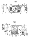
- FIG. 1 shows the circuit arrangement according to the invention in a systematic representation with a cockpit display of a motor vehicle and a control logic arranged separately therefrom for the connection of the Sensors
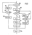
- Figure 2 is a block diagram with the central control logic and the decentralized control modules connected to it via the information line
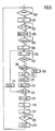
- Figure 3 shows a flow diagram of the central control logic for detecting and displaying the engine speed
- Figure 4 shows the cyclic pulse train on the information line
- Figure 5 shows a display module for the engine speed
- Figure 6 shows a flow diagram of the control module for detecting and processing the speed value.
- FIG. 1 shows a cockpit display 10, which consists of several interchangeable display modules made of LCD display elements.
- the cockpit display 10 is on the one hand grounded and on the other hand is connected to a DC voltage supply via terminal 11. It is also connected with terminal 12 to an information line 13, which starts from a central control logic 14.
- the control logic 14 is also connected to ground and via terminal 15 to a DC voltage supply. It has a large number of inputs 16, to which sensors are connected, which measure the various state variables in the motor vehicle that can be read on the cockpit display 10.
- the display modules of the cockpit display 10 comprise a speed display 17, a speed display 18, a monitoring display 19 for different, mutually independent measured variables, a status display 20 for different lighting and signaling systems, and a driving data display 21 controlled by an on-board computer.
- the various display modules are behind a printed display disc 22 of the cockpit display 10 is arranged.
- the measured values of the state variables measured by the sensors are passed to the control logic 14 via the inputs 16.
- the control logic 14 as will be explained further below, they are passed on the information line 13 in a cyclic sequence of digital signals as binary-coded numbers. From there, the measured values are read into the display modules respectively assigned to the state variables, processed and displayed via the corresponding LCD display elements of the cockpit 10.
- a first program step 100 the sensor 31 provided for the speed n of the engine, which can be the ignition generator for the ignition system of the internal combustion engine, for example, is queried.
- This sensor 31 emits a changing pulse frequency depending on the engine speed. If no speed pulse is present in program step 100, a counting register 1 is increased by the number 1 in the following program step 101. in the The following program step 102 checks whether the count register 1 has reached a predetermined maximum value. If this is not the case, program steps 100, 101 and 102 are run through until this value is reached. The speed value zero is then output in program step 103; which means the engine is stopped. This speed value zero is now stored in an output register 3 in a further step 104. With the following program section, the next sensor can now be queried.
- a predetermined time T1 of, for example, 50 microseconds is processed in the following step 205.
- a register R1 is increased from 0 to the number 1 and then in step 207 it is checked whether a further pulse a has occurred. If this is not yet the case, register R1 is incremented.
- This loop with program steps 206 and 207 is repeated until the 18th pulse a occurs.
- the number of passes in register R1 can now be used to check whether the cycle time between two successive pulses a according to FIG. 4 is time t0 or time t1.
- the register R1 has, for example, the content 10.
- the two front digits of the front BCD number remain free. If the central microcomputer 14 and the microcomputer 28 in the display module 24 are appropriately programmed, they can therefore be used for further display values, for example for monitoring certain incandescent lamps.
Landscapes
- Physics & Mathematics (AREA)
- General Physics & Mathematics (AREA)
- Control Of Indicators Other Than Cathode Ray Tubes (AREA)
- Arrangements For Transmission Of Measured Signals (AREA)
- Control Of El Displays (AREA)
Claims (7)
Applications Claiming Priority (2)
| Application Number | Priority Date | Filing Date | Title |
|---|---|---|---|
| DE19833305579 DE3305579A1 (de) | 1983-02-18 | 1983-02-18 | Schaltungsanordnung zur optischen anzeige von zustandsgroessen |
| DE3305579 | 1983-02-18 |
Publications (2)
| Publication Number | Publication Date |
|---|---|
| EP0120196A1 EP0120196A1 (fr) | 1984-10-03 |
| EP0120196B1 true EP0120196B1 (fr) | 1987-11-04 |
Family
ID=6191145
Family Applications (1)
| Application Number | Title | Priority Date | Filing Date |
|---|---|---|---|
| EP84100471A Expired EP0120196B1 (fr) | 1983-02-18 | 1984-01-18 | Agencement de circuit pour la signalisation optique de variables |
Country Status (5)
| Country | Link |
|---|---|
| US (1) | US4630043A (fr) |
| EP (1) | EP0120196B1 (fr) |
| JP (1) | JPS59162590A (fr) |
| DE (2) | DE3305579A1 (fr) |
| ES (1) | ES529829A0 (fr) |
Families Citing this family (38)
| Publication number | Priority date | Publication date | Assignee | Title |
|---|---|---|---|---|
| EP0182413A1 (fr) * | 1984-10-22 | 1986-05-28 | C. van der Lely N.V. | Ordinateur portable |
| CH667512A5 (de) * | 1984-10-24 | 1988-10-14 | Vaillant Gmbh | Steuereinrichtung fuer das betreiben von einzelelementen einer heizungsanlage. |
| DE3514438C1 (de) * | 1985-04-20 | 1986-09-18 | Porsche Ag | Zentrale Bedienungsein- und Informationsausgabe fuer Zusatzgeraete von Fahrzeugen |
| GB2189333B (en) * | 1986-03-20 | 1989-11-15 | Lucas Electrical Electronics A | Vehicle condition monitoring system |
| JPS6329229A (ja) * | 1986-07-23 | 1988-02-06 | Nissan Motor Co Ltd | 車両用診断装置 |
| DE3628333C2 (de) * | 1986-08-21 | 1996-04-04 | Bayerische Motoren Werke Ag | Multifunktionsanzeige für Kraftfahrzeuge |
| US4804937A (en) * | 1987-05-26 | 1989-02-14 | Motorola, Inc. | Vehicle monitoring arrangement and system |
| US4817118A (en) * | 1987-06-29 | 1989-03-28 | Step Engineering | Mobile incident logger |
| US4808994A (en) * | 1987-08-27 | 1989-02-28 | Riley Robert E | Logic interchange system |
| SE458886B (sv) * | 1987-09-04 | 1989-05-16 | Ericsson Telefon Ab L M | Foerfarande och system foer att oeverfoera information och styra komponenter |
| JPS6469914A (en) * | 1987-09-11 | 1989-03-15 | Yazaki Corp | Cross coil type combination meter |
| US4862365A (en) * | 1987-12-21 | 1989-08-29 | Navistar International Transportation | Universal electromechanical gauge |
| US4953110A (en) * | 1988-06-07 | 1990-08-28 | Globe Turbocharger Specialties, Inc. | Turbocharger control system |
| US4875041A (en) * | 1988-11-21 | 1989-10-17 | Navistar International Transportation Corp. | Time multiplexed control of air core gauges from a microprocessor address/data bus |
| US4991098A (en) * | 1988-11-25 | 1991-02-05 | General Motors Corporation | Computer-based controller and bipolar PWM driver arrangement for air core gauge control |
| US5136516A (en) * | 1989-12-28 | 1992-08-04 | General Signal Corporation | Analog and digital speed display device |
| DE4025104A1 (de) * | 1990-08-08 | 1992-02-13 | Kloeckner Humboldt Deutz Ag | Oeldruckniveau-anzeige |
| JP2708293B2 (ja) * | 1991-08-28 | 1998-02-04 | ローム株式会社 | 多連メータ駆動装置 |
| DE4392671T1 (de) * | 1992-06-10 | 1995-06-01 | Ford Werke Ag | Kommunikationssystem für Kraftfahrzeuge |
| JPH06213688A (ja) * | 1992-09-16 | 1994-08-05 | Caterpillar Inc | データを受け取る方法及び装置 |
| US5432497A (en) * | 1993-07-20 | 1995-07-11 | Paccar Inc. | Electronically programmable gauge |
| US5555502A (en) * | 1994-05-11 | 1996-09-10 | Geo Ventures | Display and control apparatus for the electronic systems of a motor vehicle |
| JPH11505323A (ja) * | 1995-04-18 | 1999-05-18 | カーティス インスツルメンツ インコーポレイテッド | 小型低価格半導体機器 |
| DE19832531A1 (de) * | 1998-07-22 | 2000-02-10 | Bosch Gmbh Robert | Steuerung für eine Mehrzahl von elektrischen Verbrauchern eines Kraftfahrzeugs |
| US6253143B1 (en) * | 1999-01-26 | 2001-06-26 | Veritas Dgc, Inc. | Safety limiter for powered vehicles |
| US6208919B1 (en) | 1999-09-24 | 2001-03-27 | Daimlerchrysler Corporation | Vehicle data acquisition and analysis system |
| US6871121B2 (en) | 2002-10-07 | 2005-03-22 | Blink Engineering Corp. | Entertainment system on-board a vehicle for visualizing on a display real-time vehicle data |
| US7135964B2 (en) * | 2002-11-04 | 2006-11-14 | Spx Corporation | Data link connector (DLC) driven display |
| DE20219989U1 (de) * | 2002-12-27 | 2004-06-03 | Trw Automotive Electronics & Components Gmbh & Co. Kg | Tachometer-Zeigerinstrument |
| US7680574B2 (en) * | 2004-03-04 | 2010-03-16 | Gm Global Technology Operations, Inc. | Vehicle information system with steering wheel controller |
| US7061405B2 (en) * | 2004-10-15 | 2006-06-13 | Yazaki North America, Inc. | Device and method for interfacing video devices over a fiber optic link |
| US7640085B2 (en) * | 2005-11-10 | 2009-12-29 | Gm Global Technology Operations, Inc. | Method and apparatus to provide vehicle information to a requestor |
| US20070188313A1 (en) * | 2006-02-13 | 2007-08-16 | Promate Electronic Co., Ltd. | Multi-purposed in-vehicle information display module |
| US7683771B1 (en) | 2007-03-26 | 2010-03-23 | Barry Loeb | Configurable control panel and/or dashboard display |
| US8605009B2 (en) * | 2010-12-05 | 2013-12-10 | Ford Global Technologies, Llc | In-vehicle display management system |
| US9452722B2 (en) | 2012-11-27 | 2016-09-27 | GM Global Technology Operations LLC | Induction powered panels |
| US9240276B2 (en) * | 2012-11-27 | 2016-01-19 | GM Global Technology Operations LLC | Induction powered panels |
| EP2993781A4 (fr) * | 2013-04-30 | 2016-12-14 | Fuji Electric Co Ltd | Dispositif de commande et dispositif d'entraînement pour un moteur |
Family Cites Families (16)
| Publication number | Priority date | Publication date | Assignee | Title |
|---|---|---|---|---|
| US3988730A (en) * | 1974-12-31 | 1976-10-26 | Motorola, Inc. | Multiple parameter monitoring and readout system with sampling of parameters of higher priority than the highest parameter which is out of tolerance |
| IT1061720B (it) * | 1976-06-04 | 1983-04-30 | Fiat Spa | Impianto elettrico per la distribuzione di energia particolarmente per veicoli |
| US4227181A (en) * | 1977-10-12 | 1980-10-07 | Ford Motor Company | Peripheral station in an information handling system |
| US4413341A (en) * | 1978-06-28 | 1983-11-01 | Markhasin Alexandr B | Method for exchange of data between central station and peripheral stations |
| JPS5511204A (en) * | 1978-07-10 | 1980-01-26 | Nissan Motor | Indicator for use in vehicles |
| JPS5515007A (en) * | 1978-07-19 | 1980-02-01 | Hitachi Ltd | Display control method |
| US4371934A (en) * | 1979-05-04 | 1983-02-01 | Robert Bosch Gmbh | Vehicle trip computer |
| DE2925131A1 (de) * | 1979-06-22 | 1981-01-08 | Daimler Benz Ag | Einrichtung zum anzeigen von betriebs- und rechenwerten |
| US4402073A (en) * | 1980-03-11 | 1983-08-30 | Vanderhoff Communications Ltd. | Speech and data communication network |
| US4442424A (en) * | 1980-06-11 | 1984-04-10 | Nippondenso Company, Limited | Method and system for displaying vehicle operating parameters in a variable format |
| DE3103884A1 (de) * | 1981-02-05 | 1982-09-02 | Robert Bosch Gmbh, 7000 Stuttgart | Fernwirksystem zum selektiven ansteuern von verbrauchern |
| JPS57208746A (en) * | 1981-06-18 | 1982-12-21 | Toyota Motor Corp | Transmission controlling system |
| IT1194058B (it) * | 1981-07-30 | 1988-09-14 | Fiat Auto Spa | Dispositivo per la visualizzazione selettiva a bordo di un autoveicolo di informazioni concernenti le condizioni di impiego dell autoveicolo stesso |
| DE3149291A1 (de) * | 1981-12-12 | 1983-06-23 | Robert Bosch Gmbh, 7000 Stuttgart | Schaltungsanordnung zur optischen anzeige von zustandsgroessen |
| US4464933A (en) * | 1982-11-15 | 1984-08-14 | International Harvester Co. | Steering console providing digital readout displays |
| US4551801A (en) * | 1983-02-07 | 1985-11-05 | Dickey-John Corporation | Modular vehicular monitoring system |
-
1983
- 1983-02-18 DE DE19833305579 patent/DE3305579A1/de not_active Withdrawn
-
1984
- 1984-01-18 DE DE8484100471T patent/DE3467242D1/de not_active Expired
- 1984-01-18 EP EP84100471A patent/EP0120196B1/fr not_active Expired
- 1984-02-01 US US06/575,855 patent/US4630043A/en not_active Expired - Fee Related
- 1984-02-14 JP JP59024555A patent/JPS59162590A/ja active Pending
- 1984-02-17 ES ES529829A patent/ES529829A0/es active Granted
Also Published As
| Publication number | Publication date |
|---|---|
| JPS59162590A (ja) | 1984-09-13 |
| US4630043A (en) | 1986-12-16 |
| EP0120196A1 (fr) | 1984-10-03 |
| DE3467242D1 (en) | 1987-12-10 |
| ES8501151A1 (es) | 1984-11-01 |
| DE3305579A1 (de) | 1984-08-23 |
| ES529829A0 (es) | 1984-11-01 |
Similar Documents
| Publication | Publication Date | Title |
|---|---|---|
| EP0120196B1 (fr) | Agencement de circuit pour la signalisation optique de variables | |
| EP0081807B2 (fr) | Circuit pour indication optique de grandeurs | |
| DE3103884C2 (fr) | ||
| EP0171579B1 (fr) | Dispositif pour transmettre en séries les valeurs mesurées d'au moins un transducteur | |
| DE2515202B2 (de) | Digitale vielfachmesseinrichtung | |
| DE2807604B2 (de) | Vorrichtung zur gemeinsamen Anzeige von zwei Betriebsparametern eines Kraftfahrzeugs | |
| DE3232416A1 (de) | Datenerfassungssystem fuer fahrzeuge | |
| EP0192672B2 (fr) | Procede pour controler des appareils de commande | |
| DE2904593A1 (de) | Geschwindigkeitsmeldegeraet fuer ein kraftfahrzeug | |
| DE3445617C2 (de) | Anordnung zur seriellen Übertragung der Meßwerte wenigstens eines Meßwertwandlers | |
| DE1275914B (de) | Unterwasser-Fernmesseinrichtung | |
| DE2753714A1 (de) | Einrichtung zur messung und anzeige von werten in zusammenhang mit dem kraftstoffverbrauch | |
| EP0406627B1 (fr) | Dispositif d'identification pour capteurs | |
| DE3440555C2 (fr) | ||
| DE4012610C2 (fr) | ||
| EP1082816B1 (fr) | Procede et dispositif pour actionner un compteur multietage dans un sens de comptage | |
| DE2723705C2 (de) | Prüf- und Überwachungseinrichtung für Hochfrequenz-Nachrichtenanlagen | |
| DE2543342A1 (de) | Schaltungsanordnung und verfahren zur messung der genauigkeit eines zeitmessers | |
| CH620039A5 (fr) | ||
| DE4323619C1 (de) | Einrichtung zur Übertragung einer Mehrzahl von Sensorsignalen an ein elektronisches Steuergerät | |
| DE69020364T2 (de) | Methode und Vorrichtung zum Kodieren und Lesen von Daten. | |
| DE3308610C2 (fr) | ||
| EP0158217A1 (fr) | Arrangement de couplage pour une installation signalant des dangers | |
| DE19604968C2 (de) | Verfahren zum Prüfen von inkrementalen Meßsystemen und Prüfgerät zur Durchführung des Verfahrens | |
| EP0190429A1 (fr) | Dispositif pour l'indication électronique de défauts, notamment d'une électronique de moteur d'automobiles |
Legal Events
| Date | Code | Title | Description |
|---|---|---|---|
| PUAI | Public reference made under article 153(3) epc to a published international application that has entered the european phase |
Free format text: ORIGINAL CODE: 0009012 |
|
| 17P | Request for examination filed |
Effective date: 19840118 |
|
| AK | Designated contracting states |
Designated state(s): DE FR GB IT SE |
|
| 17Q | First examination report despatched |
Effective date: 19860718 |
|
| GRAA | (expected) grant |
Free format text: ORIGINAL CODE: 0009210 |
|
| AK | Designated contracting states |
Kind code of ref document: B1 Designated state(s): DE FR GB IT SE |
|
| REF | Corresponds to: |
Ref document number: 3467242 Country of ref document: DE Date of ref document: 19871210 |
|
| ET | Fr: translation filed | ||
| GBT | Gb: translation of ep patent filed (gb section 77(6)(a)/1977) | ||
| ITF | It: translation for a ep patent filed | ||
| PLBI | Opposition filed |
Free format text: ORIGINAL CODE: 0009260 |
|
| PLAB | Opposition data, opponent's data or that of the opponent's representative modified |
Free format text: ORIGINAL CODE: 0009299OPPO |
|
| PLAB | Opposition data, opponent's data or that of the opponent's representative modified |
Free format text: ORIGINAL CODE: 0009299OPPO |
|
| 26 | Opposition filed |
Opponent name: VDO ADOLF SCHINDLING AG Effective date: 19880801 |
|
| R26 | Opposition filed (corrected) |
Opponent name: VDO ADOLF SCHINDLING AG Effective date: 19880823 |
|
| R26 | Opposition filed (corrected) |
Opponent name: VDO ADOLF SCHINDLING AG Effective date: 19880801 |
|
| ITTA | It: last paid annual fee | ||
| PLBN | Opposition rejected |
Free format text: ORIGINAL CODE: 0009273 |
|
| STAA | Information on the status of an ep patent application or granted ep patent |
Free format text: STATUS: OPPOSITION REJECTED |
|
| 27O | Opposition rejected |
Effective date: 19910324 |
|
| PGFP | Annual fee paid to national office [announced via postgrant information from national office to epo] |
Ref country code: GB Payment date: 19950110 Year of fee payment: 12 |
|
| PGFP | Annual fee paid to national office [announced via postgrant information from national office to epo] |
Ref country code: SE Payment date: 19950119 Year of fee payment: 12 |
|
| EAL | Se: european patent in force in sweden |
Ref document number: 84100471.6 |
|
| PGFP | Annual fee paid to national office [announced via postgrant information from national office to epo] |
Ref country code: FR Payment date: 19950131 Year of fee payment: 12 |
|
| PGFP | Annual fee paid to national office [announced via postgrant information from national office to epo] |
Ref country code: DE Payment date: 19950814 Year of fee payment: 12 |
|
| PG25 | Lapsed in a contracting state [announced via postgrant information from national office to epo] |
Ref country code: GB Effective date: 19960118 |
|
| PG25 | Lapsed in a contracting state [announced via postgrant information from national office to epo] |
Ref country code: SE Effective date: 19960119 |
|
| GBPC | Gb: european patent ceased through non-payment of renewal fee |
Effective date: 19960118 |
|
| PG25 | Lapsed in a contracting state [announced via postgrant information from national office to epo] |
Ref country code: FR Effective date: 19960930 |
|
| PG25 | Lapsed in a contracting state [announced via postgrant information from national office to epo] |
Ref country code: DE Effective date: 19961001 |
|
| EUG | Se: european patent has lapsed |
Ref document number: 84100471.6 |
|
| REG | Reference to a national code |
Ref country code: FR Ref legal event code: ST |