EP0120196B1 - Circuit arrangement for the optical display of variables - Google Patents
Circuit arrangement for the optical display of variables Download PDFInfo
- Publication number
- EP0120196B1 EP0120196B1 EP84100471A EP84100471A EP0120196B1 EP 0120196 B1 EP0120196 B1 EP 0120196B1 EP 84100471 A EP84100471 A EP 84100471A EP 84100471 A EP84100471 A EP 84100471A EP 0120196 B1 EP0120196 B1 EP 0120196B1
- Authority
- EP
- European Patent Office
- Prior art keywords
- display
- circuit arrangement
- values
- pulse
- display elements
- Prior art date
- Legal status (The legal status is an assumption and is not a legal conclusion. Google has not performed a legal analysis and makes no representation as to the accuracy of the status listed.)
- Expired
Links
Images

Classifications
-
- G—PHYSICS
- G01—MEASURING; TESTING
- G01D—MEASURING NOT SPECIALLY ADAPTED FOR A SPECIFIC VARIABLE; ARRANGEMENTS FOR MEASURING TWO OR MORE VARIABLES NOT COVERED IN A SINGLE OTHER SUBCLASS; TARIFF METERING APPARATUS; MEASURING OR TESTING NOT OTHERWISE PROVIDED FOR
- G01D7/00—Indicating measured values
- G01D7/02—Indicating value of two or more variables simultaneously
- G01D7/08—Indicating value of two or more variables simultaneously using a common indicating element for two or more variables
-
- G—PHYSICS
- G01—MEASURING; TESTING
- G01D—MEASURING NOT SPECIALLY ADAPTED FOR A SPECIFIC VARIABLE; ARRANGEMENTS FOR MEASURING TWO OR MORE VARIABLES NOT COVERED IN A SINGLE OTHER SUBCLASS; TARIFF METERING APPARATUS; MEASURING OR TESTING NOT OTHERWISE PROVIDED FOR
- G01D5/00—Mechanical means for transferring the output of a sensing member; Means for converting the output of a sensing member to another variable where the form or nature of the sensing member does not constrain the means for converting; Transducers not specially adapted for a specific variable
- G01D5/12—Mechanical means for transferring the output of a sensing member; Means for converting the output of a sensing member to another variable where the form or nature of the sensing member does not constrain the means for converting; Transducers not specially adapted for a specific variable using electric or magnetic means
- G01D5/25—Selecting one or more conductors or channels from a plurality of conductors or channels, e.g. by closing contacts
-
- G—PHYSICS
- G01—MEASURING; TESTING
- G01R—MEASURING ELECTRIC VARIABLES; MEASURING MAGNETIC VARIABLES
- G01R13/00—Arrangements for displaying electric variables or waveforms
Landscapes
- Physics & Mathematics (AREA)
- General Physics & Mathematics (AREA)
- Control Of Indicators Other Than Cathode Ray Tubes (AREA)
- Control Of El Displays (AREA)
- Arrangements For Transmission Of Measured Signals (AREA)
Description
Die Erfindung geht aus von einer Schaltungsanordnung zur optischen Anzeige von zustandsgrößen im Kraftfahrzeug nach dem ersten Teil des unabhängigen Anspruchs. Bei einer bekannten Schaltungsanordnung werden von einem Ringzähler verschiedene Sensoren zyklisch abgefragt, die bestimmte Zustandsgrößen im Kraftfahrzeug messen und als elektrische Meßwerte ausgeben. Die gemessenen Werte können über eine Logikschaltung als elektrische Signale in zeitlicher Folge an einer Anzeige ausgegeben und bei Defekten über verschiedene Leuchtdioden angezeigt werden. Dadurch wird der Zustand der einzelnen, von den sensoren überwachten Einrichtungen optisch angezeigt (DE-A-25 55 828, Figur 2). Diese Lösung hat vor allem den Nachteil, daß für jede Leuchtdiode eine Steuerleitung zu der zentral angeordneten Logikschaltung geführt werden muß. Außerdem können bei dieser Schaltungsanordnung nur Zustandegrößen erfaßt werden, die eine Ein- oder Austellung signalisieren. Kontinuierlich veränderliche Zustandsgrößen wie beispielsweise Fahrgeschwindigkeit, Tankfüllung und dgl. können mit dieser Schaltungsanordnung nicht genau genug angezeigt werden. Ferner muß bei einem Defekt in der Schaltungsanordnung die komplette Logikschaltung bzw. das komplette Schaltgerät ausgewechselt werden.The invention is based on a circuit arrangement for the optical display of state variables in the motor vehicle according to the first part of the independent claim. In a known circuit arrangement, various sensors are cyclically polled by a ring counter, which measure certain state variables in the motor vehicle and output them as electrical measured values. The measured values can be output via a logic circuit as electrical signals in chronological order on a display and displayed in the event of defects using various light-emitting diodes. The status of the individual devices monitored by the sensors is thereby indicated optically (DE-A-25 55 828, FIG. 2). The main disadvantage of this solution is that a control line must be routed to the centrally arranged logic circuit for each light-emitting diode. In addition, only state values can be detected in this circuit arrangement that signal an adjustment or exhibition. Continuously variable state variables such as driving speed, tank filling and the like cannot be displayed precisely enough with this circuit arrangement. Furthermore, the complete logic circuit or the complete switching device must be replaced in the event of a defect in the circuit arrangement.
Eine Schaltungsanordnung nach dem ersten Teil des unabhängigen Anspruchs ist aus der Zeitschrift Elektronik-Report 6, Juni 1880, Seiten 33 bis 34 bekannt. Die darin als "Salplex" bezeichnete Schaltungsanordnung ist unter anderem zur Anzeige von Zustandsgrößen in Kraftfahrzeugen zu verwenden und weist eine ringförmige Informationsleitung sowie eine vielzahl von Dekodier/Empfänger- und Kodier/-Geber-Einheiten auf. Dort wird für jede von einer Geber-Einheit auf eine Empfänger-Einheit zu übertragene einzelne Information ein aue 10-Bit bestehendes Datenwort erzeugt, welches 5 Bits als Empfangsadresse, 3 weitere Bits als Kanalerkennung und lediglich 1 Bit für die Information selbst enthält. Eine solche Lösung ist für die Übertragung von Meßwerten, die sich laufend ändern, ungeeignet, da für jeden analogen oder digitalen Meßwert mehrere Datenwörter benötigt werden, so daß bei der Übertragung mehrerer Meßwerte soviel Zeit benötigt wird, daß eine solche Anzeige zu träge ist. Außerdem muß jeder Geber mit einer relativ aufwendigen eigenen Kodierlogik ausgerüstet werden.A circuit arrangement according to the first part of the independent claim is known from the
Aus der Zeitschrift "internationale Elektronische Rundschau" 12, 1975, Seiten 277 bis 278, ist eine Schaltungsanordnung zur Übertragung von in Datenwörten mit Adresskode festgelegten Informationen bekannt, wobei die Datenwörter in einer zyklischen Folge auf der Datenleitung gesendet werden.From the magazine "Internationale Elektronische Rundschau" 12, 1975, pages 277 to 278, a circuit arrangement for the transmission of information defined in data words with an address code is known, the data words being sent in a cyclical sequence on the data line.
Mit der vorliegenden Lösung wird angestrebt, möglichst viele durch Sensoren digital und analog zu messende Zustandsgrößen im Kraftfahrzeug in einer Steuerlogik zusammenzufassen und als serielle digitale Signalfolge mit möglichst hoher Informationsdichte über eine Steuerleitung an dezentrale Steuermodule mit daran angeschlossenen Anzeigeelementen weiterzuleiten.The aim of the present solution is to combine as many state variables in the motor vehicle as possible to be measured digitally and analogously by sensors in a control logic and to transmit them as a serial digital signal sequence with the highest possible density of information via a control line to decentralized control modules with display elements connected to them.
Die erfindungsgemäße Schaltungsanordnung mit den kennzeichnenden Merkmalen des unabhängigen Anspruchs hat den Vorteil, daß beim Auftreten von Fehlern die zentrale Steuerlogik und die dezentralen Steuermodule voneinander getrennt überprüft und gegebenenfalle getrennt ausgewechselt werden können. Ein weiterer Vorteil besteht darin, daß eine zuverlässige Übertragung der verschiedenen Werte durch die binärkodierten Zahlen in der zyklischen Impulsfolge auf der Informationsleitung sowie eine hohe Informationsdichte erreicht wird. Außerdem können bei dieser Lösung in vorteilhafter Weiee sowohl für die zentrale Steuerlogik als auch für die dezentralen Steuermodule preisgünstige Mikrocomputer mit relativ kleinen Festwertspeichern verwendet werden. Die Mikrocomputer können dabei mehrere Alternativprogramme enthalten, von denen das richtige Programm beim Einbau der Schaltungsanordnung individuell zu dem jeweiligen Fahrzeugtyp ausgewahlt wird.The circuit arrangement according to the invention with the characterizing features of the independent claim has the advantage that when errors occur, the central control logic and the decentralized control modules can be checked separately from one another and, if necessary, replaced separately. Another advantage is that the various values are reliably transmitted by the binary-coded numbers in the cyclic pulse train on the information line, and a high information density is achieved. In addition, in this solution, inexpensive microcomputers with relatively small read-only memories can be used both for the central control logic and for the decentralized control modules. The microcomputers can contain several alternative programs, of which the correct program is selected individually for the respective vehicle type when the circuit arrangement is installed.
Durch die in den anhängigen Ansprüchen aufgeführten Maßnahmen sind vorteilhafte Weiterbildungen und Verbesserungen der im unabhängigen Anspruch angegebenen Merkmale gegeben. Eine besonders einfache und zuverlässige Übertragung der von den Sensoren Bemessenen Zustandsgrößen ist dadurch möglich, daß auf die Informationsleitung eine zyklische Folge von Impulsen gegeben wird, deren unterschiedliche Abstände voneinander als 0 bzw. 1-Signal die gemessenen Werte der Zustandsgrößen als Zahlen im BCD-Code darstellen.The measures listed in the dependent claims provide advantageous developments and improvements to the features specified in the independent claim. A particularly simple and reliable transmission of the state variables measured by the sensors is possible in that the information line is given a cyclic sequence of pulses, the different distances of which from one another as a 0 or 1 signal, the measured values of the state variables as numbers in the BCD code represent.
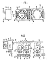
Ein Ausführungsbeispiel der Erfindung ist in der Zeichnung dargestellt und in der nachfolgenden Beschreibung näher erläutert. Es zeigen Figur 1 die erfindungsgemäße Schaltungsanordnung in systematischer Darstellung mit einer Cockpitanzeige eines Kraftfahrzeuges und einer separat davon angeordneten Steuerlogik für den Anschluß der Sensoren, Figur 2 ein Blockschaltbild mit der zentralen Steuerlogik und den über die Informationsleitung damit verbundenen dezentralen Steuermodulen, Figur 3 zeigt ein Flußdiagramm der zentralen Steuerlogik zur Erfassung und Anzeige der Motordrehzahl, Figur 4 zeigt die zyklische Impulsfolge auf der Informationsleitung, Figur 5 zeigt einen Anzeigemodul für die Motordrehzahl und Figur 6 zeigt ein Flußdiagramm des Steuermoduls zur Erfassung und Verarbeitung des Drehzahlwertes.An embodiment of the invention is shown in the drawing and explained in more detail in the following description. 1 shows the circuit arrangement according to the invention in a systematic representation with a cockpit display of a motor vehicle and a control logic arranged separately therefrom for the connection of the Sensors, Figure 2 is a block diagram with the central control logic and the decentralized control modules connected to it via the information line, Figure 3 shows a flow diagram of the central control logic for detecting and displaying the engine speed, Figure 4 shows the cyclic pulse train on the information line, Figure 5 shows a display module for the engine speed and Figure 6 shows a flow diagram of the control module for detecting and processing the speed value.
Figur 1 zeigt eine Cockpitanzeige 10, die in mehrere, auswechselbare Anzeigemodule aus LCD-Anzeigeelementen besteht. Die Cockpitanzeige 10.liegt einerseits auf Masse und ist andererseits über Klemme 11 an eine Gleichspannungsversorgung angeschlossen. Sie ist ferner mit Klemme 12 an eine Informationsleitung 13 angeschlossen, die von einer zentralen Steuerlogik 14 ausgeht. Die Steuerlogik 14 ist ebenfalls mit Masse und über Klemme 15 mit einer Gleichspannungsversorgung verbunden. Sie hat eine Vielzahl von Eingängen 16, an welche Sensoren angeschlossen werden, die die verschiedenen, auf der Cockpitanzeige 10 abzulesenden Zustandsgrößen im Kraftfahrzeug messen. Die Anzeigemodule der Cockpitanzeige 10 umfassen eine Geschwindigkeitsanzeige 17, eine Drehzahlanzeige 18, eine Überwachungsanzeige 19 für verschiedene, voneinander unabhängige Meßgrößen, eine Zustandsanzeige 20 für verschiedene Beleuchtungs- und Signalanlagen sowie eine von einem Bordcomputer gesteuerte Fahrdatenanzeige 21. Die verschiedenen Anzeigemodule sind hinter einer bedruckten Anzeigescheibe 22 der Cockpitanzeige 10 angeordnet. Die Meßwerte der von den Gebern gemessenen Zustandsgrößen werden über die Eingänge 16 auf die Steuerlogik 14 gegeben. In der Steuerlogik 14 werden sie - wie weiter hinten erläutert wird - in einer zyklischen Folge digitaler Signale als binärcodierte Zahlen auf die Informationsleitung 13 gegeben. Die Meßwerte werden von dort in die den Zustandsgrößen jeweils zugeordneten Anzeigemodule eingelesen, aufbereitet und über die entsprechenden LCD-Anzeigeelemente des Cockpits 10 zur Anzeige gebracht.Figure 1 shows a
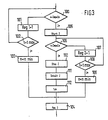
In Figur 2 ist das Blockschaltbild der erfindungsgemäßen Schaltungsanordnung dargestellt. Die Geschwindigkeitsanzeige 17, die Drehzahlanzeige 18 und die Fahrdatenanzeige 21 gehören jeweils zu einem Anzeigemodul 23, 24 und 25. Weitere Anzeigemodule für die Überwachungs- und Zustandsanzeigen 19, 20 sind - nicht dargestellt - ebenfalls an die Informationsleitung 13 angeschlossen. Die Anzeigemodule enthalten jeweils einen Steuermodul 26. Der Steuermodul 26a für die Fahrdatenanzeige 21 ist ein Fahrdatenrechner, der über ein separat angeordnetes Tastenfeld 27 zu bedienen ist. Der Steuermodul 26a enthält einen Mikroprozessor 28, dessen Ausgänge über eine Treiberstufe 35 an die einzelnen LCD-Anzeigeelemente der Fahrdatenanzeige 21 angeschlossen ist. In gleicher Weise bestehen auch die übrigen Steuermodule 26 aus jeweils einen Mikrocomputer 28, dessen Ausgänge über weitere Treiberstufen 35 mit den ihnen zugeordneten LCD-Anzeigeelementen 29 verbunden sind. Die zentrale Steuerlogik 14 besteht aus einem weiteren Mikrocomputer mit einem lKbit-EPROM-Festwert-speicher. An den Ausgängen des Mikrocomputers 14 ist eine Vielzahl von Sensoren des Kraftfahrzeuges angeschlossen, welche die anzuzeigenden Zustandsgrößen messen und von denen drei Sensoren 30, 31, 32 dargestellt sind. Die Sensoren 30, 31 und 32 geben digitale oder analoge elektrische Meßwerte über die Eingänge 16 in den Mikrocomputer 14. Alle Geber mit analogen Meßwerten werden auf solche Eingänge 16 gelegt, die einen im Mikrocomputer 14 integrierten A/D-Wandler haben. Der Mikrocomputer 14 ist außerdem noch mit mehreren Programmiereingängen 33 versehen, über die verschiedene, in seinem Festwertspeicher abgelegte Programme und Umrechnungstabellen ausgewählt werden können. Durch diese Programmiereingänge 33 können Zylinderzahl der Brennkraftmaschine, Übersetzungsverhältnis der Getriebestufen sowie die Reihenfolge der seriell ausgegebenen Anzeigedaten für verschiedene Fahrzeugtypen erfaßt und beim Einbau der Schaltungsanordnung im Fahrzeug entsprechend eingegeben werden. Über einen der Programmiereingänge 33 kann außerdem durch eine Prüftaste 34 ein Prüfprogramm aufgerufen werden, der die Funktionen des Mikrocomputers 14 prüft und bei einem Defekt ein entsprechendes Signal auf die Informationsleitung 13 oder auf eine zusätzliche Anzeige gibt.FIG. 2 shows the block diagram of the circuit arrangement according to the invention. The
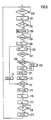
Mit Hilfe des in Figur 3 dargestellten Flußdiagrammes zur Messung der Motordrehzahl n soll die Ein- und Ausgabe der von den verschiedenen Sensoren 30, 31, 32 gemessenen Zustandsgrößen durch den Mikrocomputer 14 näher erläutert werden. Das Flußdiagramm zeigt dabei den Ausschnitt aus dem gesamten Programm des Mikroprozessors 14, der speziell zur Drehzahlmessung dient.The input and output of the state variables measured by the
In einem ersten Programmschritt 100 wird der für die Drehzahl n des Motors vorgesehene Sensor 31, der beispielsweise der Zündgeber für die Zündanlage der Brennkraftmaschine sein kann, abgefragt. Dieser Sensor 31 gibt in Abhängigkeit von der Motordrehzahl eine sich ändernde Impulsfrequenz ab. Ist beim Programmschritt 100 kein Drehzahlimpuls vorhanden, wird im folgenden Programmschritt 101 ein Zählregister 1 um die Zahl 1 erhöht. Im folgenden Programmschritt 102 wird geprüft, ob das Zählregister 1 einen vorgegebenen Maximalwert erreicht hat. Falls das nicht der Fall ist, werden die Programmschritte 100, 101 und 102 so oft durchlaufen, bis dieser Wert erreicht ist. Danach wird im Programmschritt 103 der Drehzahlwert Null ausgegeben; was bedeutet, daß der Motor stillsteht. Dieser Drehzahlwert Null wird nun in einem weiteren Schritt 104 in ein Ausgangsregister 3 abgelegt. Mit dem nachfolgenden Programmabschnitt kann nun der nächste Sensor abgefragt werden. Tritt dagegen im Programmschritt 100 am Drehzahlsensor 31 ein Impuls auf, so wird im Programmschritt 105 ein Drehzahlzähler gestartet. Im Schritt 106 wird nun geprüft, ob vom Drehzahlsensor 31 ein weiterer. Impuls eingegangen ist. Ist das nicht der Fall, wird im Programmschritt 107 ein Zählregister 2 um die Zahl 1 erhöht und im Schritt 108 wird der Stand dieses Zählregisters 2 überpruft. Auch hier wird die Programmschleife mit den Schritten 106, 107 und 108 wiederholt durchlaufen und beim Erreichen eines vorbestimmten Zählerstandes im Zählregister 2 wird im Programmschritt 108 ein Mindestwert 1 ausgegeben, der anzeigt, daß der Motor die gewünschte Leerlaufdrehzahl nicht überschritten hat. Tritt jedoch beim wiederholten Durchlauf der Programmschleife 106, 107 und 108 ein erneuter Drehzahlimpuls auf, so wird im Schritt 110 der Drehzahlzähler gestoppt. Im Schritt 111 wird der Stand des Drehzahlzählers abgelesen. Er gibt an, welche Zeit zwischen zwei aufeinanderfolgenden Drehzahlimpulsen vergangen ist. Der Zählerstand ist dabei unmittelbar umgekehrt proportional zur Motordrehzahl n. Im Programmschritt 112 wird nun unter Berücksichtigung der an einem Programmiereingang 33 eingegebenen Zylinderzahl aus dem Festwertspeicher ein Tabellenwert für die ermittelte Drehzahl n ausgelesen. Dieser Tabellenwert wird nun im nachfolgenden Schritt 104 in das Ausgangsregister 3 abgelegt. In ähnlicher Weise werden nun sämtliche Signale der angeschlossenen Sensoren verarbeitet und die ermittelten Tabellenwerte werden in entsprechende Ausgangsregister 3 abgelegt.In a
In einem späteren, nicht dargestellten Programmabschnitt werden die in den Ausgangsregistern abgelegten Zahlenwerte in einer zyklischen Signalfolge als binärkodierte Zahlen auf die Informationsleitung 13 gegeben. Die Reihenfolge der auf diese Weise vom Mikrocomputer 14 aufbereiteten Meßdaten ist dabei durch eine entsprechende Programmierung an den Programmiereingängen 33 vorgegeben. Die Signalfolge wird dabei am Ausgang des Mikrocomputers 14 als eine Folge von elektrischen impuisen a auf die Informationsleitung 13 gegeben. In Figur 4 ist eine solche, am Ausgang A des Mikrocomputers 14 erscheinende zyklische Signalfolge mit binärkodierten Zahlen dargestellt. Sie besteht in dem Beispielsfall aus einer Impulsfolge Ta von 256 Impulsen a mit einer Impulsbreite von 20 µs. Gegen Ende der Impulsfolge Ta tritt eine Synchronisationspause p auf, durch die sämtliche Steuermodule 26 zurückgesetzt werden. Durch unterschiedliche Abstände der aufeinanderfolgenden Impulse a werden die vom Mikroprozessor 14 ermittelten, in seinen Ausgangsregistern abgelegten Werte im BCD-Code als 0- bzw. 1-Signale auf die Informationsleitung 13 gegeben. Der kleine Abstand hat dabei den Wert 0 und der größere Abstand hat den Wert 1. Der Taktabstand to zweier Impulse mit dem Wert 0 beträgt 200 us und der Taktabstand t1 mit dem Wert 1 beträgt 400 µs. Die Impulsfolge Ta wird in 100 ms durchlaufen, so daß in jeder Sekunde 10 Impulszyklen auftreten.In a later program section, not shown, the numerical values stored in the output registers are passed on the
Im Beispielsfall soll eine Motordrehzahl n von 6000 min-1 vom Sensor 31 gemessen und von der Drehzahlanzeige 18 angezeigt werden. Figur 5 zeigt den dafür vorgesehenen Anzeigemodul 24. Die Drehzahlanzeige 18 ist als ringförmige Skala ausgebildet und in 27 LCD-Anzeigeelemente 29 unterteilt. Um die Drehzahl 6000 anzuzeigen, müssen die ersten 21 LCD-Anzeigeelemente 29 angesteuert werden. Dies wird nun dadurch erreicht, daß aus dem Festwertspeicher des zentralen Mikroprozessors 14 bei der vom Sensor 31 gemessenen Drehzahl von 6000 min-1 der Wert 21 im BCD-Code in die entsprechenden Ausgangsregister abgelegt wird (Schritt 104, Figur 3). Von dort wird der Wert 21 im Beispielsfall zwischen demsiebzehnten und fünfundzwanzigsten Impuls _a durch entsprechende Impulspausen ebenfalls im BCD-Code auf die Informationsleitung 13 gegeben. Der Mikrocomputer 28 des Anzeigemoduls 24 für die Drehzahlanzeige erfaßt sowohl die Impulse a als auch die Impulspausen. Durch eine Zeitschleife im Programm des Mikrocomputers 28 wird festgestellt, ob der jeweilige Impulsabstand den Wert 0 oder den Wert 1 hat bzw. ob eine Synchronisationspause p vorliegt. Die 0- und 1-Signale werden kontinuierlich in ein 8 bit-Schieberegister des Mikrocomputers 28 eingelesen. Außerdem werden die Impulse ª in einem Zählregister des Mikrocomputers 28 gezählt, der durch eine Pin-Programmierung des Mikrocomputers 28 auf eine bestimmte Zahl eingestellt ist. Da nun der zentrale Mikrocomputer 14 zwischen dem 17. und 25. Impuls a den Drehzahlwert 21 im BCD-Code auf die Informationsleitung 13 gibt, ist dieser Wert mit dem 25. Impuls im Mikrocomputer 28 gespeichert. Dieser gespeicherte Wert wird nun durch den Mikrocomputer 28 dekodiert und über entsprechende Umrechnungstabellen, welche in seinem Festwertspeicher abgelegt sind, werden seine Ausgange aktiviert. Dabei werden die Ausgänge 1 bis 21 mit einem 1-Signal belegt und die Ausgänge 22 bis 27 mit einem 0-Signal. Über die nachgeschaltete Treiberstufe 35 werden nun die ersten 21 LCD-Anzeigeelemente 29 aktiviert und dadurch die Motordrehzahl 6000 min-1 angezeigt.In the example, an engine speed to n measured by the sensor 31 and are displayed by the
In Figur 6 ist ein Programm dargestellt, mit dem der Mikrocomputer 28 in Figur 5 die für ihn bestimmte Information für die Motordrehzahl n aus der in Figur dargestellten Impulsfolge Ta herausliest. Im ersten Programmschritt 200 prüft der Mikrocomputer 28, ob auf der Informationsleitung 13 ein Impuls vorhanden ist. Sobald ein solcher Impuls a auftritt, wird das Zählregister im Schritt 201 um die Zahl 1 erhöht. Im nächsten Programmschritt 202 wird der Zählerstand geprüft. Mit dem 16. Impuls _a erreicht das Zählregister die Zahl 16 und mit dem folgenden Programmschritt 203 werden mehrere Register R1, R2, R3 auf 0 gesetzt und damit zum Einlesen der gewünschten Drehzahlinformation vorbereitet. Im folgenden Schritt 204 wird nun der nachfolgende 17. Impuls abgewartet. Sobald er auftritt, wird im folgenden Schritt 205 eine vorgegebene Zeit T1 von beispielsweise 50 µs abgearbeitet. Danach wird im Schritt 206 ein Register R1 von 0 auf die Zahl 1 erhöht und anschließend wird im Schritt 207 geprüft, ob ein weiterer Impuls a aufgetreten ist. Ist dies noch nicht der Fall, so wird das Register R1 inkrementiert. Diese Schleife mit den Programmschritten 206 und 207 wird so oft durchlaufen, bis der 18. Impuls a auftritt. Durch die im Register R1 stehende Zahl der Durchläufe kann nun geprüft werden, ob die Taktzeit zwischen zwei aufeinanderfolgenden Impulsen a gemäß Figur 4 die Zeit t0 oder die Zeit t1 ist. Bei einer Taktzeit t0, die den Informationswert 0 darstellt, hat das Register R1 beispielsweise den Inhalt 10. Bei einer Taktzeit tl, welche den Informationswert 1 darstellt, wird dagegen das Register R1 bis auf den Wert 30 inkrementiert. Im nachfolgenden Programmschritt 208 wird nun geprüft, ob der Inhalt des Registers R1 größer als 10 ist. Ist dies nicht der Fall, so wurde ein Taktabstand t0 mit dem Wert 0 ermittelt und im Programmschritt 209 wird nun das Carry-Register auf 0 gesetzt. Ist dagegen der Inhalt des Registers R1 größer als 10, so wurde ein Taktabstand t1 mit dem Informationswert 1 ermittelt und das Carry-Register wird im Schritt 210 auf 1 gesetzt. Im nachfolgenden Programmschritt 211 wird ein Register R2 zusammen mit dem Carry-Register um einen Schritt rotiert und damit wird der erste Wert äus der Drehzahlinformation der Impulsfolge Ta in die erste Stelle des Registers R2 gerückt. Im folgenden Schritt 212 wird ein weiteres Register R3 um 1 erhöht. Im Schritt 213 wird nun geprüft, ob das Register R3 auf den Wert 8 gestellt wurde. Solange dies nicht der Fall ist, wird in einem weiteren Programmschritt 214 das Register R1 wieder auf Null zurückgesetzt und die Schritte 206 und 207 werden nun erneut zyklisch durchlaufen, bis der nächste Impuls auftritt.FIG. 6 shows a program with which the
Auf diese Weise werden nun die durch die Taktabstände t0 und t1 der Impulsfolge Ta dargestellten Informationswerte zwischen dem 17. und 25. Impuls a ermittelt und im Register R2 eingespeichert. Mit dem 25. Impuls a erreicht das Register R3 im Programmschritt 212 den Wert 8. Im nachfolgenden Schritt 215 wird nun der Inhalt des Registers R2 in ein weiteres Register R4 umgespeichert und im Schritt 216 wird nun über die im Register R4 abgespeicherte Drehzahlinformation aus einer ROM-Tabelle ein Wert abgerufen, der im Programmschritt 217 zur Ansteuerung der entsprechenden Anzeigeelemente 29 als 0- und 1-Signale auf die 27 Ausgänge des Mikrocomputer 28 gelangt. Im Schritt 218 wird nun die Synchronisationspause p abgewartet und im Schritt 219 wird das Zählregister auf 0 zurückgesetzt. Danach springt das Programm wieder auf den Schritt 200 zurück und die Motordrehzahl wird mit der nachfolgenden Impulsfolge Ta erneut in das Anzeigemodul 24 eingelesen.In this way, the information values represented by the clock intervals t0 and t1 of the pulse train Ta between the 17th and 25th pulses a are determined and stored in register R2. With the 25th pulse a, the register R3 reaches the value 8 in the
Da zur Drehzahlanzeige nur 27 LCD-Anzeigeelemente benötigt werden, bleiben die zwei vorderen Stellen der vorderen BCD-Zahl frei. Sie können daher bei entsprechender Programmierung des zentralen Mikrocomputers 14 und des Mikrocomputers 28 im Anzeigemodul 24 für weitere Anzeigewerte, beispielsweise für die Überwachung bestimmter Glühlampen verwendet werden.Since only 27 LCD display elements are required for the speed display, the two front digits of the front BCD number remain free. If the central microcomputer 14 and the
Der Mikrocomputer 28 ist außerdem mit weiteren Eingängen 36 versehen, auf denen der anzuzeigende Wert gegebenenfalls auch in einer parallelen Dateneingabe übermittelt werden kann. Über einen Programmiereingang 37 wird in diesem Fall festgelegt, ob die über die Informationsleitung 13 in dem Mikrocomputer 28 gelangende serielle Dateneingabe oder die über die Eingänge 36 gelangende parallele Dateneingabe ausgewertet werden soll. Außerdem ist es auch möglich, zusätzlich zur seriellen Dateneingabe über die Informationsleitung 13 bestimmte Signalgeber unmittelbar über die Eingänge 36 an den Mikrocomputer 28 anzuschließen und dessen Signale mit zu verarbeiten. Ferner kann über einen weiteren Programmiereingang 38 der Mikrocomputer 28 mit einem Prüfprogramm getestet werden.The
Der Mikrocomputer 28 für die Fahrdatenanzeige 21 muß als Fahrdatenrechner arbeiten und bei entsprechender Betätigung des Tastenfeldes 27 Fahrzeit, Benzinverbrauch, Durchschnittsgeschwindigkeit und dgl. berechnen können. Außerdem soll er immer dann die Uhrzeit anzeigen, wenn keine Fahrdaten abgerufen werden. Zur Ermittlung der jeweils gewünschten Fahrdaten benötigt er verschiedene, vom zentralen Mikrocomputer 14 ausgegebene Werte. Um diese Werte aus der zyklischen Signalfolge auf der Informationsleitung 13 herauszulesen, müssen mehrere Programmabschnitte gemäß Figur 6 durchlaufen und dabei das Zählregister jeweils so umgeschaltet werden, daß er alle zur Berechnung der Fahrdaten benötigten Werte aus der zyklischen Signalfolge auslesen und mit einem internen Programm verarbeiten kann.The
Die Erfindung ist nicht auf das dargestellte Ausführungsbeispiel beschränkt. So ist es ohne weiteres möglich, die auf der Informationsleitung 13 zu übertragenden Daten als eine Folge von 0- bzw. 1-Signaten im einfachen Binärcode oder in einem 1 aus n-Code zu übertragen. Die 0- oder 1-Signale können dabei auch durch unterschiedlich breite Impulse a übertragen werden, wobei dann alle lmpulspausen mit Ausnahme der Synchronisationspause p gleich sind. Erfindungswesentlich ist jedoch, daß die zentrale Steuerlogik 14 eine zyklische Signalfolge von binärkodierten Zahlen auf die Informationsleitung 13 gibt, welche den Werten entsprechen, die von den verschiedenen Sensoren ermittelt werden. Wesentlich ist ferner, daß jeder Steuermodul einen Impulszähler und eine Dekodierstufe enthält, die gemäß Figur 6 durch ein µ C-Programm realisiert sein können. Der Zähler wählt die dem Steuermodul zugeordneten binärkodierten Zahlen aus der zyklischen Signalfolge aus und die Dekodierstufe setzt diese Binärzahlen in 1- bzw. 0-Signale um. Durch diese Signale werden nun die Anzeigeelemente 29 angesteuert, welche die von den Gebern gemessenen Werte wiedergeben. Dabei können anstelle von LCD-Anzeigeelementen 29 auch Leuchtdioden, Vakuum-Fluoreszenz-Displays oder andere aktive, quasiaktive oder nichtaktive Anzeigeelemente verwendet werden. Üblicherweise ist die Informationsleitung 13 eine Kupferleitung und die zyklische Signalfolge wird durch elektrische Impulse a übertragen. Im Rahmen der Erfindung ist es aber auch möglich, die Informationsleitung 13 als Glasfaser weiter auszubilden, auf den die ermittelten Daten in einer zyklischen Folge von Lichtimpulsen übertragen werden.The invention is not restricted to the exemplary embodiment shown. So it is easily possible on the
Durch die Verwendung einer intelligenten Steuerung in den Steuermodulen ist es möglich, die zentrale Steuerlogik in einem Mikrocomputer mit relativ kleinem Speicher zu realisieren. Die Weiterverarbeitung der übermittelten Daten erfolgt dabei in den intelligenten Steuerungen der Steuermodule 26. Bei einem Defekt können so mit geringem Reparaturaufwand einzelne Module ausgewechselt werden. Die Aufgliederung der vollständigen Cockpit-Anzeige 10 in einzelne Steuer- und Anzeigemodule wird dabei zweckmäßigerweise so gewählt, daß die kostenintensiven Baugruppen voneinander und von den übrigen Teilen der Cockpit-Anzeige zu trennen sind. Dabei kann es unter Umständen zweckmäßig sein, die kostenintensiven Anzeige-Displays so aufzugliedern, daß mehrere Displayplatinen an ein und demselben Steuermodul angeschlossen werden. Steuermodule und Anzeige-Displays sind miteinander lösbar verbunden und voneinander getrennt auswechselbar.By using an intelligent controller in the control modules, it is possible to implement the central control logic in a microcomputer with a relatively small memory. The transmitted data are further processed in the intelligent controls of the
Um möglichst wenig lösbare Kontaktstellen zu bekommen, ist es zweckmäßig, wenn jeder Steuermodul mit den ihm zugeordneten Anzeigeelementen fest verbunden als auswechselbarer Anzeigemodul ausgebildet ist.In order to get as few detachable contact points as possible, it is expedient if each control module with the display elements assigned to it is designed as an exchangeable display module.
Bei der in Figur 2 dargestellten Ausführung der erfindungsgemäßen Schaltungsanordnung wird beispielsweise für die zentrale Steuerlogik 14 der Mikrocomputer 8748 der Firma Intel und für die Steuermodule 26 der Mikrocomputer 6805 der Firma Motorola verwendet.In the embodiment of the circuit arrangement according to the invention shown in FIG. 2, the microcomputer 8748 from Intel and for the
Claims (7)
Applications Claiming Priority (2)
| Application Number | Priority Date | Filing Date | Title |
|---|---|---|---|
| DE3305579 | 1983-02-18 | ||
| DE19833305579 DE3305579A1 (en) | 1983-02-18 | 1983-02-18 | CIRCUIT ARRANGEMENT FOR THE OPTICAL DISPLAY OF STATE SIZES |
Publications (2)
| Publication Number | Publication Date |
|---|---|
| EP0120196A1 EP0120196A1 (en) | 1984-10-03 |
| EP0120196B1 true EP0120196B1 (en) | 1987-11-04 |
Family
ID=6191145
Family Applications (1)
| Application Number | Title | Priority Date | Filing Date |
|---|---|---|---|
| EP84100471A Expired EP0120196B1 (en) | 1983-02-18 | 1984-01-18 | Circuit arrangement for the optical display of variables |
Country Status (5)
| Country | Link |
|---|---|
| US (1) | US4630043A (en) |
| EP (1) | EP0120196B1 (en) |
| JP (1) | JPS59162590A (en) |
| DE (2) | DE3305579A1 (en) |
| ES (1) | ES529829A0 (en) |
Families Citing this family (38)
| Publication number | Priority date | Publication date | Assignee | Title |
|---|---|---|---|---|
| US4684089A (en) * | 1984-10-22 | 1987-08-04 | Lely Cornelis V D | Computer with universal input member for use on stationary and mobile platforms |
| CH667512A5 (en) * | 1984-10-24 | 1988-10-14 | Vaillant Gmbh | Control for burners mixers and pumps in central heating installation |
| DE3514438C1 (en) * | 1985-04-20 | 1986-09-18 | Porsche Ag | Central operating input and information output for additional devices of vehicles |
| GB2189333B (en) * | 1986-03-20 | 1989-11-15 | Lucas Electrical Electronics A | Vehicle condition monitoring system |
| JPS6329229A (en) * | 1986-07-23 | 1988-02-06 | Nissan Motor Co Ltd | Diagnosing device for vehicle |
| DE3628333C2 (en) * | 1986-08-21 | 1996-04-04 | Bayerische Motoren Werke Ag | Multi-function display for motor vehicles |
| US4804937A (en) * | 1987-05-26 | 1989-02-14 | Motorola, Inc. | Vehicle monitoring arrangement and system |
| US4817118A (en) * | 1987-06-29 | 1989-03-28 | Step Engineering | Mobile incident logger |
| US4808994A (en) * | 1987-08-27 | 1989-02-28 | Riley Robert E | Logic interchange system |
| SE458886B (en) * | 1987-09-04 | 1989-05-16 | Ericsson Telefon Ab L M | PROCEDURES AND SYSTEMS TO TRANSFER INFORMATION AND CONTROL COMPONENTS |
| JPS6469914A (en) * | 1987-09-11 | 1989-03-15 | Yazaki Corp | Cross coil type combination meter |
| US4862365A (en) * | 1987-12-21 | 1989-08-29 | Navistar International Transportation | Universal electromechanical gauge |
| US4953110A (en) * | 1988-06-07 | 1990-08-28 | Globe Turbocharger Specialties, Inc. | Turbocharger control system |
| US4875041A (en) * | 1988-11-21 | 1989-10-17 | Navistar International Transportation Corp. | Time multiplexed control of air core gauges from a microprocessor address/data bus |
| US4991098A (en) * | 1988-11-25 | 1991-02-05 | General Motors Corporation | Computer-based controller and bipolar PWM driver arrangement for air core gauge control |
| US5136516A (en) * | 1989-12-28 | 1992-08-04 | General Signal Corporation | Analog and digital speed display device |
| DE4025104A1 (en) * | 1990-08-08 | 1992-02-13 | Kloeckner Humboldt Deutz Ag | Oil pressure level display, esp. for internal combustion engine - has evaluation circuit computing desired pressure from engine revolution rate and oil temp. |
| JP2708293B2 (en) * | 1991-08-28 | 1998-02-04 | ローム株式会社 | Multiple meter drive |
| WO1993025412A1 (en) * | 1992-06-10 | 1993-12-23 | Ford Motor Company Limited | A communication system for motor vehicles |
| JPH06213688A (en) * | 1992-09-16 | 1994-08-05 | Caterpillar Inc | Method and device for receiving data |
| US5432497A (en) * | 1993-07-20 | 1995-07-11 | Paccar Inc. | Electronically programmable gauge |
| US5555502A (en) * | 1994-05-11 | 1996-09-10 | Geo Ventures | Display and control apparatus for the electronic systems of a motor vehicle |
| JPH11505323A (en) * | 1995-04-18 | 1999-05-18 | カーティス インスツルメンツ インコーポレイテッド | Small and low-priced semiconductor equipment |
| DE19832531A1 (en) * | 1998-07-22 | 2000-02-10 | Bosch Gmbh Robert | Control for a plurality of electrical consumers of a motor vehicle |
| US6253143B1 (en) * | 1999-01-26 | 2001-06-26 | Veritas Dgc, Inc. | Safety limiter for powered vehicles |
| US6208919B1 (en) | 1999-09-24 | 2001-03-27 | Daimlerchrysler Corporation | Vehicle data acquisition and analysis system |
| US6871121B2 (en) | 2002-10-07 | 2005-03-22 | Blink Engineering Corp. | Entertainment system on-board a vehicle for visualizing on a display real-time vehicle data |
| US7135964B2 (en) * | 2002-11-04 | 2006-11-14 | Spx Corporation | Data link connector (DLC) driven display |
| DE20219989U1 (en) * | 2002-12-27 | 2004-06-03 | Trw Automotive Electronics & Components Gmbh & Co. Kg | Tachometer pointer instrument |
| US7680574B2 (en) * | 2004-03-04 | 2010-03-16 | Gm Global Technology Operations, Inc. | Vehicle information system with steering wheel controller |
| US7061405B2 (en) * | 2004-10-15 | 2006-06-13 | Yazaki North America, Inc. | Device and method for interfacing video devices over a fiber optic link |
| US7640085B2 (en) * | 2005-11-10 | 2009-12-29 | Gm Global Technology Operations, Inc. | Method and apparatus to provide vehicle information to a requestor |
| US20070188313A1 (en) * | 2006-02-13 | 2007-08-16 | Promate Electronic Co., Ltd. | Multi-purposed in-vehicle information display module |
| US7683771B1 (en) | 2007-03-26 | 2010-03-23 | Barry Loeb | Configurable control panel and/or dashboard display |
| US8605009B2 (en) * | 2010-12-05 | 2013-12-10 | Ford Global Technologies, Llc | In-vehicle display management system |
| US9452722B2 (en) | 2012-11-27 | 2016-09-27 | GM Global Technology Operations LLC | Induction powered panels |
| US9240276B2 (en) * | 2012-11-27 | 2016-01-19 | GM Global Technology Operations LLC | Induction powered panels |
| CN105027426B (en) * | 2013-04-30 | 2017-06-09 | 富士电机株式会社 | The drive device of control device and motor |
Family Cites Families (16)
| Publication number | Priority date | Publication date | Assignee | Title |
|---|---|---|---|---|
| US3988730A (en) * | 1974-12-31 | 1976-10-26 | Motorola, Inc. | Multiple parameter monitoring and readout system with sampling of parameters of higher priority than the highest parameter which is out of tolerance |
| IT1061720B (en) * | 1976-06-04 | 1983-04-30 | Fiat Spa | ELECTRIC SYSTEM FOR THE DISTRIBUTION OF ENERGY PARTICULARLY FOR VEHICLES |
| US4227181A (en) * | 1977-10-12 | 1980-10-07 | Ford Motor Company | Peripheral station in an information handling system |
| US4413341A (en) * | 1978-06-28 | 1983-11-01 | Markhasin Alexandr B | Method for exchange of data between central station and peripheral stations |
| JPS5511204A (en) * | 1978-07-10 | 1980-01-26 | Nissan Motor | Indicator for use in vehicles |
| JPS5515007A (en) * | 1978-07-19 | 1980-02-01 | Hitachi Ltd | Display control method |
| US4371934A (en) * | 1979-05-04 | 1983-02-01 | Robert Bosch Gmbh | Vehicle trip computer |
| DE2925131A1 (en) * | 1979-06-22 | 1981-01-08 | Daimler Benz Ag | DEVICE FOR DISPLAYING OPERATING AND CALCULATING VALUES |
| US4402073A (en) * | 1980-03-11 | 1983-08-30 | Vanderhoff Communications Ltd. | Speech and data communication network |
| US4442424A (en) * | 1980-06-11 | 1984-04-10 | Nippondenso Company, Limited | Method and system for displaying vehicle operating parameters in a variable format |
| DE3103884A1 (en) * | 1981-02-05 | 1982-09-02 | Robert Bosch Gmbh, 7000 Stuttgart | REMOTE CONTROL SYSTEM FOR SELECTIVE CONTROL OF CONSUMERS |
| JPS57208746A (en) * | 1981-06-18 | 1982-12-21 | Toyota Motor Corp | Transmission controlling system |
| IT1194058B (en) * | 1981-07-30 | 1988-09-14 | Fiat Auto Spa | DEVICE FOR SELECTIVE DISPLAY ON BOARD A VEHICLE OF INFORMATION CONCERNING THE CONDITIONS OF USE OF THE VEHICLE ITSELF |
| DE3149291A1 (en) * | 1981-12-12 | 1983-06-23 | Robert Bosch Gmbh, 7000 Stuttgart | CIRCUIT ARRANGEMENT FOR THE OPTICAL DISPLAY OF STATE SIZES |
| US4464933A (en) * | 1982-11-15 | 1984-08-14 | International Harvester Co. | Steering console providing digital readout displays |
| US4551801A (en) * | 1983-02-07 | 1985-11-05 | Dickey-John Corporation | Modular vehicular monitoring system |
-
1983
- 1983-02-18 DE DE19833305579 patent/DE3305579A1/en not_active Withdrawn
-
1984
- 1984-01-18 DE DE8484100471T patent/DE3467242D1/en not_active Expired
- 1984-01-18 EP EP84100471A patent/EP0120196B1/en not_active Expired
- 1984-02-01 US US06/575,855 patent/US4630043A/en not_active Expired - Fee Related
- 1984-02-14 JP JP59024555A patent/JPS59162590A/en active Pending
- 1984-02-17 ES ES529829A patent/ES529829A0/en active Granted
Also Published As
| Publication number | Publication date |
|---|---|
| DE3467242D1 (en) | 1987-12-10 |
| EP0120196A1 (en) | 1984-10-03 |
| ES8501151A1 (en) | 1984-11-01 |
| JPS59162590A (en) | 1984-09-13 |
| US4630043A (en) | 1986-12-16 |
| ES529829A0 (en) | 1984-11-01 |
| DE3305579A1 (en) | 1984-08-23 |
Similar Documents
| Publication | Publication Date | Title |
|---|---|---|
| EP0120196B1 (en) | Circuit arrangement for the optical display of variables | |
| EP0081807B2 (en) | Circuit for the optical indication of parameters | |
| DE3103884C2 (en) | ||
| DE2515202C3 (en) | Digital multiple measuring device | |
| EP0171579B1 (en) | Arrangement for the serial transmission of measured values of at least one transducer | |
| DE2838256A1 (en) | DEVICE FOR CONTROLLING A OIL METER AND A SPEEDOMETER | |
| DE2807604B2 (en) | Device for the common display of two operating parameters of a motor vehicle | |
| DE3232416A1 (en) | Data acquisition system for vehicles | |
| EP0192672B2 (en) | Method for checking control apparatuses | |
| DE2904593A1 (en) | SPEED DETECTOR FOR A MOTOR VEHICLE | |
| DE1275914B (en) | Underwater remote measuring device | |
| DE2753714A1 (en) | DEVICE FOR MEASURING AND DISPLAYING VALUES RELATED TO FUEL CONSUMPTION | |
| EP0406627B1 (en) | Identification device for sensors | |
| DE3440555C2 (en) | ||
| DE4012610C2 (en) | ||
| EP1082816B1 (en) | Method and system for operating a multi-stage counter in one counting direction | |
| DE2723705C2 (en) | Testing and monitoring device for high-frequency communication systems | |
| DE3447639C2 (en) | ||
| DE4323619C1 (en) | Apparatus for the transmission of a plurality of sensor signals to an electronic control device | |
| DE3500440A1 (en) | DEVICE FOR ELECTRONIC ERROR DISPLAY, IN PARTICULAR MOTOR ELECTRONICS IN MOTOR VEHICLES | |
| DE3308610C2 (en) | ||
| EP0158217A1 (en) | Circuit arrangement for a danger-indicating installation | |
| DE19604968C2 (en) | Method for testing incremental measuring systems and testing device for carrying out the method | |
| DE3030266A1 (en) | Analogue chart recorder with alphanumeric printer - embodies data preparation circuit assembling annotation data for synchronised printing | |
| EP1394558A1 (en) | Device for safety testing an analog-to-digital converter |
Legal Events
| Date | Code | Title | Description |
|---|---|---|---|
| PUAI | Public reference made under article 153(3) epc to a published international application that has entered the european phase |
Free format text: ORIGINAL CODE: 0009012 |
|
| 17P | Request for examination filed |
Effective date: 19840118 |
|
| AK | Designated contracting states |
Designated state(s): DE FR GB IT SE |
|
| 17Q | First examination report despatched |
Effective date: 19860718 |
|
| GRAA | (expected) grant |
Free format text: ORIGINAL CODE: 0009210 |
|
| AK | Designated contracting states |
Kind code of ref document: B1 Designated state(s): DE FR GB IT SE |
|
| REF | Corresponds to: |
Ref document number: 3467242 Country of ref document: DE Date of ref document: 19871210 |
|
| ET | Fr: translation filed | ||
| GBT | Gb: translation of ep patent filed (gb section 77(6)(a)/1977) | ||
| ITF | It: translation for a ep patent filed |
Owner name: STUDIO JAUMANN |
|
| PLBI | Opposition filed |
Free format text: ORIGINAL CODE: 0009260 |
|
| PLAB | Opposition data, opponent's data or that of the opponent's representative modified |
Free format text: ORIGINAL CODE: 0009299OPPO |
|
| PLAB | Opposition data, opponent's data or that of the opponent's representative modified |
Free format text: ORIGINAL CODE: 0009299OPPO |
|
| 26 | Opposition filed |
Opponent name: VDO ADOLF SCHINDLING AG Effective date: 19880801 |
|
| R26 | Opposition filed (corrected) |
Opponent name: VDO ADOLF SCHINDLING AG Effective date: 19880823 |
|
| R26 | Opposition filed (corrected) |
Opponent name: VDO ADOLF SCHINDLING AG Effective date: 19880801 |
|
| ITTA | It: last paid annual fee | ||
| PLBN | Opposition rejected |
Free format text: ORIGINAL CODE: 0009273 |
|
| STAA | Information on the status of an ep patent application or granted ep patent |
Free format text: STATUS: OPPOSITION REJECTED |
|
| 27O | Opposition rejected |
Effective date: 19910324 |
|
| PGFP | Annual fee paid to national office [announced via postgrant information from national office to epo] |
Ref country code: GB Payment date: 19950110 Year of fee payment: 12 |
|
| PGFP | Annual fee paid to national office [announced via postgrant information from national office to epo] |
Ref country code: SE Payment date: 19950119 Year of fee payment: 12 |
|
| EAL | Se: european patent in force in sweden |
Ref document number: 84100471.6 |
|
| PGFP | Annual fee paid to national office [announced via postgrant information from national office to epo] |
Ref country code: FR Payment date: 19950131 Year of fee payment: 12 |
|
| PGFP | Annual fee paid to national office [announced via postgrant information from national office to epo] |
Ref country code: DE Payment date: 19950814 Year of fee payment: 12 |
|
| PG25 | Lapsed in a contracting state [announced via postgrant information from national office to epo] |
Ref country code: GB Effective date: 19960118 |
|
| PG25 | Lapsed in a contracting state [announced via postgrant information from national office to epo] |
Ref country code: SE Effective date: 19960119 |
|
| GBPC | Gb: european patent ceased through non-payment of renewal fee |
Effective date: 19960118 |
|
| PG25 | Lapsed in a contracting state [announced via postgrant information from national office to epo] |
Ref country code: FR Effective date: 19960930 |
|
| PG25 | Lapsed in a contracting state [announced via postgrant information from national office to epo] |
Ref country code: DE Effective date: 19961001 |
|
| EUG | Se: european patent has lapsed |
Ref document number: 84100471.6 |
|
| REG | Reference to a national code |
Ref country code: FR Ref legal event code: ST |