EP0116727B1 - Regelverfahren für eine Entstaubungsanlage - Google Patents
Regelverfahren für eine Entstaubungsanlage Download PDFInfo
- Publication number
- EP0116727B1 EP0116727B1 EP83201819A EP83201819A EP0116727B1 EP 0116727 B1 EP0116727 B1 EP 0116727B1 EP 83201819 A EP83201819 A EP 83201819A EP 83201819 A EP83201819 A EP 83201819A EP 0116727 B1 EP0116727 B1 EP 0116727B1
- Authority
- EP
- European Patent Office
- Prior art keywords
- pressure loss
- loss value
- control process
- suction
- control
- Prior art date
- Legal status (The legal status is an assumption and is not a legal conclusion. Google has not performed a legal analysis and makes no representation as to the accuracy of the status listed.)
- Expired
Links
- 238000000034 method Methods 0.000 title claims abstract description 17
- 239000000428 dust Substances 0.000 title claims abstract description 9
- 238000000605 extraction Methods 0.000 title claims description 6
- 230000004075 alteration Effects 0.000 claims 2
- 230000003247 decreasing effect Effects 0.000 claims 2
- 239000007789 gas Substances 0.000 claims 1
- 238000004886 process control Methods 0.000 claims 1
- 239000002912 waste gas Substances 0.000 claims 1
- 230000001105 regulatory effect Effects 0.000 description 6
- 241001136792 Alle Species 0.000 description 1
- 238000004140 cleaning Methods 0.000 description 1
- 238000011144 upstream manufacturing Methods 0.000 description 1
Images

Classifications
-
- B—PERFORMING OPERATIONS; TRANSPORTING
- B01—PHYSICAL OR CHEMICAL PROCESSES OR APPARATUS IN GENERAL
- B01D—SEPARATION
- B01D46/00—Filters or filtering processes specially modified for separating dispersed particles from gases or vapours
- B01D46/42—Auxiliary equipment or operation thereof
- B01D46/44—Auxiliary equipment or operation thereof controlling filtration
- B01D46/46—Auxiliary equipment or operation thereof controlling filtration automatic
-
- C—CHEMISTRY; METALLURGY
- C21—METALLURGY OF IRON
- C21C—PROCESSING OF PIG-IRON, e.g. REFINING, MANUFACTURE OF WROUGHT-IRON OR STEEL; TREATMENT IN MOLTEN STATE OF FERROUS ALLOYS
- C21C5/00—Manufacture of carbon-steel, e.g. plain mild steel, medium carbon steel or cast steel or stainless steel
- C21C5/28—Manufacture of steel in the converter
- C21C5/38—Removal of waste gases or dust
Definitions
- the invention relates to a control method for a dedusting system, in which a plurality of gas streams are extracted from locally separated dust sources, fed to a dedusting device via a collecting line and conveyed into an exhaust gas chimney by means of a controllable suction fan.
- Such systems are usually operated in such a way that either the pressure in the manifold is regulated to a constant value and the negative pressures at the individual suction points are set only once by hand, or that a suction point is regulated on behalf of the entire system. Both operating modes only lead to a reasonably satisfactory result if there are no major fluctuations at any point in the dedusting system.
- the known control methods are inadequate because they have to be on the safe side with regard to optimal dedusting, i. H. that too high negative pressures are set and excessive amounts of gas are extracted.
- the induced draft fan is oversized and is operated below the design point for most of the time and yet is operated at too high a power. The result is inappropriately high investment and operating costs, which unnecessarily drive up the dedusting costs.
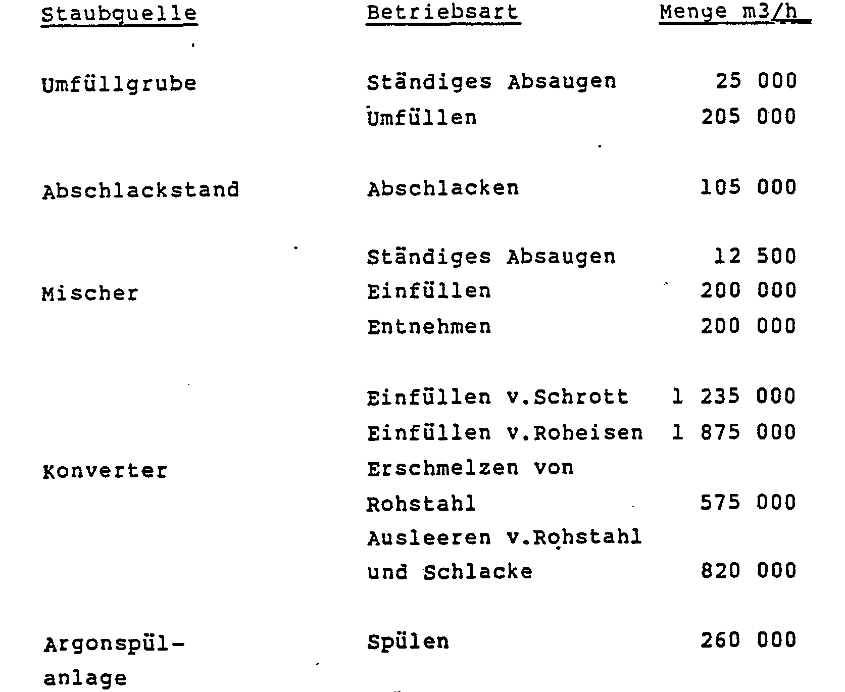
- dedusting system with a plurality of locally separated extraction points can be found in steelworks, where in addition to a main dedusting system for the converter, dedusting systems for collecting and cleaning the so-called secondary dust sources are also increasingly being provided.
- the following table shows some sources of secondary dust in steelworks with their gas quantities generated under different operating conditions.
- the pressure loss value R is increased when the control element at at least one suction point exceeds an adjustable value x below “fully open, or that the pressure loss value R is reduced if the control elements have an adjustable value at all suction points y below «fully opened.
- the change in the pressure loss value R is advantageously carried out step by step.
- the values x and y and the change steps in terms of size and chronological sequence are matched to the inertia of the overall system.
- digitally operating regulators are used in the regulating method and, in the case of a large number of regulating points, the superordinate regulating tasks are carried out by a process computer.
- FIG. 1 in which an exemplary embodiment with two suction points is shown schematically.
- the pressure at the respective suction point 12, 13 is recorded with a pressure transducer 1 and in the controller 2 with that at the setpoint r ; 3 set value compared.
- the controller 2 adjusts the flap 4 in the sense of the control deviation until the control deviation has become zero.
- the pressure upstream of the dedusting system 11 is measured with the pressure transducer 7 and compared in the controller 8 with the value set on the set point adjuster R 9.
- the gas flow to the chimney 15 is changed in the sense of the control deviation by changing the fan speed or by adjusting a swirl regulator 10 on the fan 14 until the pressure has reached the set value.
- control signal y from the controller 3 or the flap position is 100%, there is still a control deviation.
- Control deviation Xw and control signal y or flap position are applied to another controller 5, a so-called master controller. If the control signal or the damper position is 100% and there is still a control deviation, controller 5 increases its output signal.
- the guide controller 5 reduces its output signal and the negative pressure in the gas manifold 16 is reduced.
- the decisive factor for increasing the negative pressure is the largest output signal from the master controller 5. Of the maximum value selection 6, only the largest signal is passed on to the slave controller 8.
Landscapes
- Chemical & Material Sciences (AREA)
- Engineering & Computer Science (AREA)
- Chemical Kinetics & Catalysis (AREA)
- Environmental & Geological Engineering (AREA)
- Manufacturing & Machinery (AREA)
- Materials Engineering (AREA)
- Metallurgy (AREA)
- Organic Chemistry (AREA)
- Filtering Of Dispersed Particles In Gases (AREA)
- Waste-Gas Treatment And Other Accessory Devices For Furnaces (AREA)
- Electrostatic Separation (AREA)
- Control Of Positive-Displacement Air Blowers (AREA)
Description
- Die Erfindung bezieht sich auf ein Regelverfahren für eine Entstaubungsanlage, bei der eine Mehrzahl von Gasströmen von örtlich getrennten Staubquellen abgesaugt, über eine Sammelleitung einer Entstaubungseinrichtung zugeführt und mittels regelbarem Saugzuggebläse in einen Abgaskamin gefördert wird.
- Derartige Anlagen werden üblicherweise so betrieben, daß entweder der Druck in der Sammelleitung auf einen konstanten Wert geregelt wird und die Unterdrücke an den einzelnen Absaugstellen von Hand nur einmal eingestellt werden oder aber, daß eine Absaugstelle stellvertretend für das gesamte System geregelt wird. Beide Betriebsweisen führen nur dann zu einem einigermaßen befriedigenden Ergebnis, wenn an keiner Stelle der Entstaubungsanlage größere Schwankungen auftreten. In allen anderen Fällen sind die bekannten Regelverfahren unzureichend, weil sie im Hinblick auf eine optimale Entstaubung auf der sicheren Seite liegen müssen, d. h. daß zu hohe Unterdrücke eingestellt und zu hohe Gasmengen abgesaugt werden. In der Regel ist bei derartigen Anlagen das Saugzuggebläse überdimensioniert und wird die meiste Zeit unterhalb des Auslegungspunktes und trotzdem mit zu hoher Leistung betrieben. Die Folge sind unangemessen hohe Investions- und Betriebskosten, die die Aufwendungen für die Entstaubung unnötig in die Höhe treiben.
- Ein Beispiel für eine Entstaubungsanlage mit einer Mehrzahl örtlich getrennter Absaugstellen findet man in Stahlwerken, wo neben einer Hauptentstaubungsanlage für den Konverter in zunehmendem Maße auch Entstaubungsanlagen zur Erfassung und Reinigung der sogenannten Nebenstaubquellen vorgesehen werden. In der folgenden Tabelle sind einige Nebenstaubquellen in Stahlwerken mit ihren bei verschiedenen Betriebszuständen anfallenden Gasmengen zusammengestellt.
- Es leuchtet unmittelbar ein, daß bei Schwankungen des Gasanfalls an einzelnen Absaugstellen zwischen 0 und 100% und am Saugzuggebläse zwischen 10 und 100% die bekannten Regelverfahren verbesserungsbedürftig sind. Daraus ergibt sich die Aufgabe, für eine Entstaubungsanlage der eingangs genannten Art ein Regelverfahren vorzuschlagen, mit dem auf die Schwankungen an den einzelnen Absaugstellen besser reagiert werden kann und das ein Betreiben der Anlage mit geringstmöglichen Investions- und Betriebskosten erlaubt.
- Zur Lösung dieser Aufgabe wird ein Regelverfahren vorgeschlagen, das dadurch gekennzeichnet ist, daß der Unterdruck an jeder Absaugstelle auf einen vorgegebenen Sollwert r; eingeregelt wird, daß das Saugzuggebläse auf einen vorgegebenen Druckverlustwert R der Gesamtanlage eingeregelt wird und daß der Druckverlustwert R folgendermaßen geändert wird :
- a) ist an wenigstens einer Absaugstelle bei voll geöffnetem Regelorgan der Unterdruck geringer als vorgegeben, wird der Druckverlustwert R so lange erhöht, bis an allen Absaugstellen die vorgegebenen Unterdruckwerte erreicht sind,
- b) sind an allen Absaugstellen die vorgegebenen Unterdruckwerte erreicht und alle Regelorgane teilweise geschlossen, wird der Druckverlustwert R so lange erniedrigt, bis wenigstens an einer Absaugstelle das Regelorgan voll geöffnet ist.
- In weiterer Ausbildung des Erfindungsgedankens ist vorgesehen, daß der Druckverlustwert R erhöht wird, wenn an wenigstens einer Absaugstelle das Regelorgan einen einstellbaren Wert x unterhalb « voll geöffnet überschreitet bzw., daß der Druckveriustwert R erniedrigt wird, wenn an allen Absaugstellen die Regelorgane einen einstellbaren Wert y unterhalb « voll geöffnet unterschreiten. Vorteilhafterweise erfolgt die Änderung des Druckverlustwertes R schrittweise. Schließlich ist es zweckmäßig, wenn die Werte x und y und die Änderungsschritte hinsichtlich Größe und zeitlicher Abfolge auf die Regelträgheit der Gesamtanlage abgestimmt werden. Vorteilhafterweise werden bei dem Regelverfahren digital arbeitende Regler verwendet und bei einer großen Anzahl von Regelstellen die übergeordneten Regelaufgaben von einem Prozeßrechner vorgenommen.
- Weitere Einzelheiten werden anhand von Figur 1 erläutert, in der schematisch ein Ausführungsbeispiel mit zwei Absaugstellen dargestellt ist.
- Der Druck an der jeweiligen Absaugstelle 12, 13 wird mit einem Druckmeßumformer 1 erfaßt und im Regler 2 mit dem am Sollwert r; 3 eingestellten Wert verglichen. Bei einer Regelabweichung verstellt der Regler 2 die Klappe 4 im Sinne der Regelabweichung so lange, bis die Regelabweichung zu Null geworden ist.
- Der Druck vor der Entstaubungsanlage 11 wird mit dem Druckmeßumformer 7 gemessen und im Regler 8 mit dem am Sollwertsteller R 9 eingestellten Wert verglichen. Bei einer Regelabweichung wird durch Änderung der Gebläsedrehzahl oder durch Verstellung eines Drallreglers 10 am Gebläse 14 der Gasdurchfluß zum Kamin 15 im Sinne der Regelabweichung so lange verändert, bis der Druck den eingestellten Wert erreicht hat.
- Reicht der Unterdruck an einer der Absaugstellen 12, 13 trotz voll geöffneter Klappe 4 nicht aus, d. h. das Stellsignal y des Reglers 3 bzw. die Klappenstellung betragen 100%, so steht weiterhin eine Regelabweichung an. Regelabweichung Xw und Stellsignal y bzw. Klappenstellung werden einem weiteren Regler 5, einem sogenannten Führungsregler aufgeschaltet. Ist das Stellsignal bzw. die Klappenstellung 100% und steht weiterhin eine Regelabweichung an, so erhöht der Regler 5 sein Ausgangssignal.
- Dieses wird im Regler 8 zu dem im Sollwertsteller R 9 eingestellten Wert addiert, wodurch vom Regler 8 als sogenanntem Folgeregler der Unterdruck in der Gassammelleitung 16 und somit der Gasdurchfluß erhöht wird, bis die Regelabweichung am Regler 2 zu Null geworden ist.
- Verläßt die Klappe 4 ihre AUF-Stellung, so verringert der Führungsregler 5 sein Ausgangssignal und der Unterdruck in der Gassammelleitung 16 wird erniedrigt. Maßgebend für die Erhöhung des Unterdruckes ist das größte Ausgangssignal der Führungsregler 5. Von der Maximalwertauswahl 6 wird nur das größte Signal an den Folgeregier 8 weitergegeben.
- Der Einfachheit halber wurden nur zwei Absaugstellen im Verfahrensbild dargestellt. Das erfindungsgemäße Verfahren ist darauf jedoch nicht begrenzt und kann bei jeder Anzahl von Absaugstellen, die in der Praxis vorkommen, angewendet werden.
Claims (6)
Priority Applications (1)
| Application Number | Priority Date | Filing Date | Title |
|---|---|---|---|
| AT83201819T ATE35915T1 (de) | 1983-01-20 | 1983-12-20 | Regelverfahren fuer eine entstaubungsanlage. |
Applications Claiming Priority (2)
| Application Number | Priority Date | Filing Date | Title |
|---|---|---|---|
| DE19833301668 DE3301668A1 (de) | 1983-01-20 | 1983-01-20 | Regelverfahren fuer eine entstaubungsanlage |
| DE3301668 | 1983-01-20 |
Publications (3)
| Publication Number | Publication Date |
|---|---|
| EP0116727A2 EP0116727A2 (de) | 1984-08-29 |
| EP0116727A3 EP0116727A3 (en) | 1987-01-07 |
| EP0116727B1 true EP0116727B1 (de) | 1988-07-27 |
Family
ID=6188652
Family Applications (1)
| Application Number | Title | Priority Date | Filing Date |
|---|---|---|---|
| EP83201819A Expired EP0116727B1 (de) | 1983-01-20 | 1983-12-20 | Regelverfahren für eine Entstaubungsanlage |
Country Status (5)
| Country | Link |
|---|---|
| US (1) | US4521226A (de) |
| EP (1) | EP0116727B1 (de) |
| JP (1) | JPS59139913A (de) |
| AT (1) | ATE35915T1 (de) |
| DE (2) | DE3301668A1 (de) |
Families Citing this family (13)
| Publication number | Priority date | Publication date | Assignee | Title |
|---|---|---|---|---|
| US4701192A (en) * | 1985-05-31 | 1987-10-20 | Tidewater Industrial Components, Inc. | Vacuum system |
| JPS6249924A (ja) * | 1985-08-23 | 1987-03-04 | ジエ−ムス フエイ | 集塵ダクト吸引圧制御方法及び装置 |
| GB8616185D0 (en) * | 1986-07-02 | 1986-08-06 | Ici Plc | Pressure control |
| US4865629A (en) * | 1988-07-05 | 1989-09-12 | Industrial Filter & Pump Mfg. Co. | Control of particle size distribution in gas filtration |
| DE69324373T2 (de) | 1992-10-31 | 1999-08-26 | Sato | ZAHNBüRSTE UND ELEKTRISCH ANGETRIEBENE ZAHNBüRSTE |
| US5505763A (en) * | 1994-10-07 | 1996-04-09 | Nordson Corporation | System and method for controlling air flow through a powder coating booth |
| GB9506365D0 (en) * | 1995-03-28 | 1995-05-17 | British Steel Plc | Process control,method and apparatus |
| US5711785A (en) * | 1995-10-26 | 1998-01-27 | Ormet Corporation | Method and apparatus for controlling the cleaning cycle of air filter elements and for predicting the useful life thereof |
| DE19825638A1 (de) * | 1998-06-09 | 1999-12-16 | Hartwig Straub | Ausgleichsfilterapparat |
| US20090215375A1 (en) * | 2003-03-06 | 2009-08-27 | Greenvex | Fan Assemblies, Mechanical Draft Systems and Methods |
| CN102978331B (zh) * | 2012-12-04 | 2014-05-07 | 中冶赛迪工程技术股份有限公司 | 一种提高新og转炉煤气回收的控制方法 |
| DE102012224510A1 (de) | 2012-12-28 | 2014-07-03 | Sms Siemag Ag | Abgasanlage und Verfahren zu deren Betrieb |
| DE102013224615A1 (de) | 2013-11-29 | 2015-06-03 | Sms Siemag Ag | Verfahren und Vorrichtung zum energieeffizienten Betrieb von sekundären Entstaubungsanlagen |
Family Cites Families (8)
| Publication number | Priority date | Publication date | Assignee | Title |
|---|---|---|---|---|
| DE976156C (de) * | 1953-03-11 | 1963-04-04 | Maschf Augsburg Nuernberg Ag | Selbsttaetige Regelung der Verbrennungsluftmenge bei Mischfeuerungen |
| US3655361A (en) * | 1969-11-20 | 1972-04-11 | Chemical Construction Corp | Controlled removal of off-gas from oxygen steel converters |
| DE2523082B2 (de) * | 1975-05-24 | 1977-09-01 | Gottfried Bischoff Bau kompl. Gasreinigungs- und Wasserrückkühlanlagen KG, 4300 Essen | Gichtgasreinigungsanlage fuer druckhochoefen |
| US4201555A (en) * | 1976-12-30 | 1980-05-06 | Joseph Tkach | Method and apparatus for degasification of liquid by induced vortexing |
| US4160407A (en) * | 1977-11-18 | 1979-07-10 | Bell Telephone Laboratories, Incorporated | Ventilating system |
| JPS55132678A (en) * | 1979-04-02 | 1980-10-15 | Kawasaki Steel Co | Method of concentrating and collecting dust in exhaust gas containing dust generated at plural position |
| JPS6047497B2 (ja) * | 1981-05-25 | 1985-10-22 | 東プレ株式会社 | 集中式空気調和設備の風量制御装置 |
| JPS57207521A (en) * | 1981-06-17 | 1982-12-20 | Kawasaki Steel Corp | Operating method for dust collection system for central dust collection of dusty waste gases generated in plural places |
-
1983
- 1983-01-20 DE DE19833301668 patent/DE3301668A1/de not_active Withdrawn
- 1983-12-20 DE DE8383201819T patent/DE3377469D1/de not_active Expired
- 1983-12-20 EP EP83201819A patent/EP0116727B1/de not_active Expired
- 1983-12-20 AT AT83201819T patent/ATE35915T1/de not_active IP Right Cessation
-
1984
- 1984-01-06 US US06/568,856 patent/US4521226A/en not_active Expired - Lifetime
- 1984-01-19 JP JP59007920A patent/JPS59139913A/ja active Granted
Also Published As
| Publication number | Publication date |
|---|---|
| US4521226A (en) | 1985-06-04 |
| ATE35915T1 (de) | 1988-08-15 |
| JPS59139913A (ja) | 1984-08-11 |
| DE3301668A1 (de) | 1984-07-26 |
| EP0116727A2 (de) | 1984-08-29 |
| EP0116727A3 (en) | 1987-01-07 |
| DE3377469D1 (en) | 1988-09-01 |
| JPH0413005B2 (de) | 1992-03-06 |
Similar Documents
| Publication | Publication Date | Title |
|---|---|---|
| EP0116727B1 (de) | Regelverfahren für eine Entstaubungsanlage | |
| EP0515596B1 (de) | Produktspeiseautomatik und verfahren zur steuerung eines müllereiwalzenstuhles | |
| EP0058305B1 (de) | Steuerung von Turboverdichtern zum Verhindern des Pumpens | |
| EP0303023B1 (de) | Eine faserverarbeitende Anlage und Verfahren zu dessen Steuerung | |
| DE3531310A1 (de) | Reinluftgenerator | |
| EP0335105B1 (de) | Verfahren zur Vermeidung des Pumpens eines Turboverdichters mittels Abblaseregelung | |
| DE3047426A1 (de) | Verfahren zur regelung der luftmenge | |
| EP0143931A2 (de) | Einrichtung zur Belüftung und Klimatisierung von Fahrgasträumen in Schienenfahrzeugen | |
| DE3215073A1 (de) | Regelanordnung fuer feuerungsanlagen bei dampf- oder heizkesseln | |
| DE811578C (de) | Pneumatische Foerderanlage mit mehreren an ein gemeinsames Geblaese angeschlossenen Foerderrohren, insbesondere fuer Muehlen mit mehreren Passagen | |
| DE1274852B (de) | Ausgleichsvorrichtung fuer mehrere parallel arbeitende Gasturbinenanlagen | |
| WO1981002724A1 (en) | Method for adjusting the transport conditions in a pneumatic conveyor and pneumatic plant in a flour-mill for implementing such method | |
| DE3001778A1 (de) | Verfahren und einrichtung zur wegregelung eines positionsantriebes | |
| DE19801041C1 (de) | Verfahren zum Betrieb eines Radialverdichters mit verstellbaren Vorleit- und Nachleitapparaten bei Änderungen des Arbeitspunktes im Verdichterkennfeld | |
| DE7606107U1 (de) | Bogenfalzautomat | |
| EP0086337B1 (de) | Verfahren zur Regelung des Luftüberschusses an Feuerungen sowie Regeleinrichtung zur Ausführung des Verfahrens | |
| EP0352619A2 (de) | Verfahren zur Regelung der Feuerleistung bei Verbrennungsanlagen | |
| DE2236613B2 (de) | Vorrichtung zum Regeln der Gutschichthöhe einer Wirbelschichtanlage | |
| DE3938083C2 (de) | ||
| EP0561792A1 (de) | Wissensbasierte steuer- und regeleinrichtung. | |
| DE2638456C3 (de) | Verfahren zum Anfahren von Regelkreisen | |
| EP0334030B1 (de) | Regeleinrichtung für einen Druckregelkreis | |
| DE3024743C2 (de) | Regelvorrichtung für eine pneumatische Förderanlage | |
| DE4122631A1 (de) | Verfahren zum geregelten betreiben von verdichtern | |
| DE915413C (de) | Einrichtung zur Regelung mindestens einer UEbergabeleistung in einem von verschiedenen Kraftmaschinengruppen aus gespeisten Netzverband |
Legal Events
| Date | Code | Title | Description |
|---|---|---|---|
| PUAI | Public reference made under article 153(3) epc to a published international application that has entered the european phase |
Free format text: ORIGINAL CODE: 0009012 |
|
| AK | Designated contracting states |
Designated state(s): AT BE DE FR GB IT LU NL SE |
|
| PUAL | Search report despatched |
Free format text: ORIGINAL CODE: 0009013 |
|
| AK | Designated contracting states |
Kind code of ref document: A3 Designated state(s): AT BE DE FR GB IT LU NL SE |
|
| 17P | Request for examination filed |
Effective date: 19870217 |
|
| 17Q | First examination report despatched |
Effective date: 19871030 |
|
| GRAA | (expected) grant |
Free format text: ORIGINAL CODE: 0009210 |
|
| AK | Designated contracting states |
Kind code of ref document: B1 Designated state(s): AT BE DE FR GB IT LU NL SE |
|
| REF | Corresponds to: |
Ref document number: 35915 Country of ref document: AT Date of ref document: 19880815 Kind code of ref document: T |
|
| REF | Corresponds to: |
Ref document number: 3377469 Country of ref document: DE Date of ref document: 19880901 |
|
| ET | Fr: translation filed | ||
| ITF | It: translation for a ep patent filed | ||
| GBT | Gb: translation of ep patent filed (gb section 77(6)(a)/1977) | ||
| PLBE | No opposition filed within time limit |
Free format text: ORIGINAL CODE: 0009261 |
|
| STAA | Information on the status of an ep patent application or granted ep patent |
Free format text: STATUS: NO OPPOSITION FILED WITHIN TIME LIMIT |
|
| 26N | No opposition filed | ||
| PGFP | Annual fee paid to national office [announced via postgrant information from national office to epo] |
Ref country code: SE Payment date: 19910912 Year of fee payment: 9 |
|
| PGFP | Annual fee paid to national office [announced via postgrant information from national office to epo] |
Ref country code: FR Payment date: 19910917 Year of fee payment: 9 |
|
| PGFP | Annual fee paid to national office [announced via postgrant information from national office to epo] |
Ref country code: LU Payment date: 19911227 Year of fee payment: 9 |
|
| ITTA | It: last paid annual fee | ||
| PGFP | Annual fee paid to national office [announced via postgrant information from national office to epo] |
Ref country code: NL Payment date: 19911231 Year of fee payment: 9 |
|
| EPTA | Lu: last paid annual fee | ||
| PG25 | Lapsed in a contracting state [announced via postgrant information from national office to epo] |
Ref country code: LU Free format text: LAPSE BECAUSE OF NON-PAYMENT OF DUE FEES Effective date: 19921220 |
|
| PG25 | Lapsed in a contracting state [announced via postgrant information from national office to epo] |
Ref country code: SE Effective date: 19921221 |
|
| PG25 | Lapsed in a contracting state [announced via postgrant information from national office to epo] |
Ref country code: NL Effective date: 19930701 |
|
| NLV4 | Nl: lapsed or anulled due to non-payment of the annual fee | ||
| PG25 | Lapsed in a contracting state [announced via postgrant information from national office to epo] |
Ref country code: FR Effective date: 19930831 |
|
| REG | Reference to a national code |
Ref country code: FR Ref legal event code: ST |
|
| EUG | Se: european patent has lapsed |
Ref document number: 83201819.6 Effective date: 19930709 |
|
| PGFP | Annual fee paid to national office [announced via postgrant information from national office to epo] |
Ref country code: GB Payment date: 19971113 Year of fee payment: 15 |
|
| PGFP | Annual fee paid to national office [announced via postgrant information from national office to epo] |
Ref country code: AT Payment date: 19971126 Year of fee payment: 15 |
|
| PGFP | Annual fee paid to national office [announced via postgrant information from national office to epo] |
Ref country code: DE Payment date: 19971128 Year of fee payment: 15 |
|
| PGFP | Annual fee paid to national office [announced via postgrant information from national office to epo] |
Ref country code: BE Payment date: 19971208 Year of fee payment: 15 |
|
| PG25 | Lapsed in a contracting state [announced via postgrant information from national office to epo] |
Ref country code: DE Free format text: LAPSE BECAUSE OF THE APPLICANT RENOUNCES Effective date: 19980306 |
|
| PG25 | Lapsed in a contracting state [announced via postgrant information from national office to epo] |
Ref country code: GB Free format text: LAPSE BECAUSE OF NON-PAYMENT OF DUE FEES Effective date: 19981220 Ref country code: AT Free format text: LAPSE BECAUSE OF NON-PAYMENT OF DUE FEES Effective date: 19981220 |
|
| PG25 | Lapsed in a contracting state [announced via postgrant information from national office to epo] |
Ref country code: BE Free format text: LAPSE BECAUSE OF NON-PAYMENT OF DUE FEES Effective date: 19981231 |
|
| BERE | Be: lapsed |
Owner name: METALLGESELLSCHAFT A.G. Effective date: 19981231 |
|
| GBPC | Gb: european patent ceased through non-payment of renewal fee |
Effective date: 19981220 |