EP0116363B1 - Poche à colostomie munie d'un dispositif pour filtrer et contrôler l'évacuation des gaz - Google Patents
Poche à colostomie munie d'un dispositif pour filtrer et contrôler l'évacuation des gaz Download PDFInfo
- Publication number
- EP0116363B1 EP0116363B1 EP19840101213 EP84101213A EP0116363B1 EP 0116363 B1 EP0116363 B1 EP 0116363B1 EP 19840101213 EP19840101213 EP 19840101213 EP 84101213 A EP84101213 A EP 84101213A EP 0116363 B1 EP0116363 B1 EP 0116363B1
- Authority
- EP
- European Patent Office
- Prior art keywords
- bag
- colostomy
- bag according
- valve
- interior
- Prior art date
- Legal status (The legal status is an assumption and is not a legal conclusion. Google has not performed a legal analysis and makes no representation as to the accuracy of the status listed.)
- Expired
Links
- 239000007789 gas Substances 0.000 title claims description 46
- 238000001914 filtration Methods 0.000 title claims description 7
- 238000013022 venting Methods 0.000 title 1
- 239000000463 material Substances 0.000 claims description 21
- 238000005192 partition Methods 0.000 claims description 11
- 230000000968 intestinal effect Effects 0.000 claims description 6
- 239000003054 catalyst Substances 0.000 claims description 5
- 239000002245 particle Substances 0.000 claims description 4
- 239000000654 additive Substances 0.000 claims description 3
- 230000000903 blocking effect Effects 0.000 claims description 2
- 239000004744 fabric Substances 0.000 claims description 2
- 239000006260 foam Substances 0.000 claims description 2
- 239000008187 granular material Substances 0.000 claims description 2
- 239000012528 membrane Substances 0.000 claims description 2
- VNWKTOKETHGBQD-UHFFFAOYSA-N methane Chemical class C VNWKTOKETHGBQD-UHFFFAOYSA-N 0.000 claims description 2
- 239000004745 nonwoven fabric Substances 0.000 claims description 2
- 239000002759 woven fabric Substances 0.000 claims description 2
- 239000003463 adsorbent Substances 0.000 claims 1
- 230000029142 excretion Effects 0.000 claims 1
- 230000035515 penetration Effects 0.000 claims 1
- OKTJSMMVPCPJKN-UHFFFAOYSA-N Carbon Chemical compound [C] OKTJSMMVPCPJKN-UHFFFAOYSA-N 0.000 description 4
- 238000004519 manufacturing process Methods 0.000 description 4
- 239000007788 liquid Substances 0.000 description 3
- 230000007812 deficiency Effects 0.000 description 2
- 210000000936 intestine Anatomy 0.000 description 2
- 238000000034 method Methods 0.000 description 2
- 239000000126 substance Substances 0.000 description 2
- 238000010521 absorption reaction Methods 0.000 description 1
- 238000007792 addition Methods 0.000 description 1
- 230000000996 additive effect Effects 0.000 description 1
- 239000000853 adhesive Substances 0.000 description 1
- 238000007599 discharging Methods 0.000 description 1
- 230000000694 effects Effects 0.000 description 1
- 230000002349 favourable effect Effects 0.000 description 1
- 239000000835 fiber Substances 0.000 description 1
- 230000010354 integration Effects 0.000 description 1
- 210000002011 intestinal secretion Anatomy 0.000 description 1
- 230000035943 smell Effects 0.000 description 1
- 238000001179 sorption measurement Methods 0.000 description 1
- 239000003053 toxin Substances 0.000 description 1
- 231100000765 toxin Toxicity 0.000 description 1
- 108700012359 toxins Proteins 0.000 description 1
- 238000009423 ventilation Methods 0.000 description 1
- 238000003466 welding Methods 0.000 description 1
Images
Classifications
-
- A—HUMAN NECESSITIES
- A61—MEDICAL OR VETERINARY SCIENCE; HYGIENE
- A61F—FILTERS IMPLANTABLE INTO BLOOD VESSELS; PROSTHESES; DEVICES PROVIDING PATENCY TO, OR PREVENTING COLLAPSING OF, TUBULAR STRUCTURES OF THE BODY, e.g. STENTS; ORTHOPAEDIC, NURSING OR CONTRACEPTIVE DEVICES; FOMENTATION; TREATMENT OR PROTECTION OF EYES OR EARS; BANDAGES, DRESSINGS OR ABSORBENT PADS; FIRST-AID KITS
- A61F5/00—Orthopaedic methods or devices for non-surgical treatment of bones or joints; Nursing devices; Anti-rape devices
- A61F5/44—Devices worn by the patient for reception of urine, faeces, catamenial or other discharge; Portable urination aids; Colostomy devices
- A61F5/441—Devices worn by the patient for reception of urine, faeces, catamenial or other discharge; Portable urination aids; Colostomy devices having venting or deodorant means, e.g. filters ; having antiseptic means, e.g. bacterial barriers
Definitions
- the invention relates to a colostomy bag with a device for filtering and controlled removal of malodorous intestinal gases, which has a special filter chamber for receiving a filter material, which has a gas outlet opening leading to the outside, and via a gas inlet opening which is closed by means of a manually operable valve and with the bag holding the intestinal secretions. Interior is connected.
- So-called colostomy bags are used to hold the deposits in people with an artificial intestinal exit. H. especially the stool from the intestine.
- gases are generated in the intestine, which then also get into the colostomy pouch and cause it to expand accordingly.
- the aim here is to provide the patient with a possibility for the controlled emptying of the colostomy pouch from the gases, so that the patient has the opportunity to release the gases at a time when he feels unobserved, but also to do so Possibility to keep a certain gas cushion in the bag, thereby avoiding that the bag walls stick together, which could also lead to difficulties.
- a colostomy bag is known from EP-A-0 064 044, which has a filter chamber for receiving a filter material. When flowing through this filter chamber, the unpleasant smells are eliminated to some extent. However, there is no guarantee that complete odor removal will be achieved, which is why the patient using the bag must always fear the escape of unpleasant smelling gases.
- Another deficiency in the known colostomy pouch is that no gas cushion can build up in it, since the gases can always flow freely into the open. As a result, there is a fear that the walls of the bag will stick to each other as well as to the patient's skin, thereby increasing the absorption capacity. of the bag can be reduced and when adhering to the patient's skin there is a risk that the skin in the area of the bag will become sore.
- a bag of the type mentioned in the opening paragraph is finally known from US-A-2 054 535.
- the filter chamber is a separate element which is fastened to the outside of the bag and which is connected to an outlet opening of the bag via a hose.
- a plug-like valve element is provided in this outlet opening.
- the deficiencies explained with regard to the pouch according to DE-U-81 33 695 basically also occur because of the presence of a connecting tube.
- this known bag is expensive to manufacture and uncomfortable to use because of the separate, comparatively large and stiff filter element.
- the invention is therefore based on the object of designing a colostomy bag in such a way that the patient has both the possibility of discharging the gases in a controlled manner with simultaneous filtering without the risk of the bag being emptied unintentionally.
- the device for filtering and controlled removal of intestinal gases is integrated into the bag by providing the filter chamber in the bag, which with the rest of the bag interior the valve is in direct connection.
- the filter and ventilation device are therefore not provided separately but integrated in the bag, for which purpose a special chamber for receiving the filter material is provided in the bag on the one hand in a known manner, but on the other hand a valve between the filter chamber and the remaining bag interior is integrated.
- a special chamber for receiving the filter material is provided in the bag on the one hand in a known manner, but on the other hand a valve between the filter chamber and the remaining bag interior is integrated.
- the bag according to the invention has the essential advantage that the gas outlet can be controlled as desired according to the needs of the patient, so that on the one hand the patient can only let gas flow out when he feels undisturbed, and on the other hand it is possible to always keep a certain amount of residual gas in the bag, so that the bag walls can neither stick to each other nor to the patient's skin. Bags according to the invention can be produced very easily and inexpensively because of the integration of the filter element and the valve, so that every stoma patient is given the opportunity to use appropriate bags, and he no longer has to rely - as is usually the case - on draining the gases perforate the bag. In addition, however, the handling is very simple in comparison to the bags which have been customary hitherto and are equipped with a separate valve arrangement.
- the filter chamber is separated from the interior of the bag by a transverse wall running close and approximately parallel to the upper edge of the bag, the gas outlet opening advantageously being arranged on one end and the gas inlet opening on the other end of the elongated filter chamber .
- the transverse wall can be used separately or can only be formed by a weld seam between the two bag walls.
- valves known per se can of course be used as the valve.
- a particularly simple design is obtained, however, if, as provided according to the invention, the valve is essentially a lip valve formed by two parallel, elastically bendable plates, the plates lying against one another in the closed position and by lateral pressure in the direction of their plane in the open position can be bent apart.
- a lip valve of this type consisting of two platelets can be easily produced, for example in a welding process, which complies with the endeavor to reduce the cost of manufacturing the colostomy bag.
- the platelets forming the lip valve are arranged transversely to the bag walls in a special outlet chamber which is separated from the rest of the bag interior by means of a gas-permeable transverse wall.
- a gas-permeable transverse wall which is separated from the rest of the bag interior by means of a gas-permeable transverse wall.
- the plates are arranged approximately parallel to the transverse wall on an approximately perpendicular to this partition wall of the outlet chamber, the partition wall preferably simultaneously forming the end wall of the filter chamber having the gas inlet opening.
- the lip valve In order to ensure that the lip valve always functions reliably, it can be favorable if the transverse wall has only small openings which prevent particles from blocking the passage.
- a wide variety of substances can be used as filter material.
- adsorber grains preferably activated carbon grains
- filter material it is possible to use adsorber grains, preferably activated carbon grains, as filter material, since then on the one hand a sufficient gas throughput and on the other hand a correspondingly good adsorption can be achieved.
- web-shaped or filter material activated by additives flat materials, e.g. B. nonwovens, woven fabrics, knitted fabrics, foams or activated fibers.
- the use of such filter materials can above all bring advantages in their handling during manufacture compared to the use of granules.
- the material is activated by appropriate additions, e.g. B. of activated carbon, catalysts or the like.
- the gases can be cleaned by chemisorption, which in particular also removes toxins.
- the catalyst can be used as an additive to another filter material or as the only filter material, possibly in a suitable combination of several catalysts.
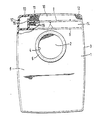
- the colostomy bag consists of two walls 1, 2 which are parallel to one another and which are connected along their edge via a weld seam 3.
- the wall 1 of the colostomy bag has an opening 4 which is surrounded by a self-adhesive ring 5.
- a bag part is divided over a transverse wall 6.
- the transverse wall 6 is provided with comparatively small passage openings 7 which, although allowing gas from the interior 8 of the bag to pass between the walls 1, 2 below the transverse wall 6, do not allow other substances located in the bag interior 8 to pass through.
- an elongated filter chamber 10 is divided over a transverse wall 9 and is filled with a corresponding filter material 11, for example activated carbon granules.
- the elongated filter chamber 10 has in the area of its right end in the drawing a gas outlet opening 12 at the top, in the area of the left end, likewise at the top, a gas inlet opening 13.
- a partition 15 which extends from the lower transverse wall 6 upwards over the transverse wall 9 forming the bottom of the filter chamber 10. The upper edge of this partition 15 delimits the gas inlet opening 13.
- the partition 15 serves as a support for two mutually parallel plates 16 made of elastically bendable material, which protrude transversely to the partition 15 and form a lip valve.
- the arrangement and design of the platelets 16 is such that they rest against one another in the rest position and are moved apart by lateral pressure (perpendicular to the plane of the drawing). In the closed position, in which the plates 16 resiliently abut against one another, no gas can escape from the outlet chamber 14 via the intermediate. Chamber 17 and the gas inlet opening 13 flow into the filter chamber 10.
- the passage openings 7 in the transverse wall 6 should be so small that, although they allow unimpeded gas passage from the bag interior 8 into the outlet chamber 14, they prevent any particles which could get stuck between the plates 16 in the open position from passing through. If particles would stick between the platelets 16 during use, the lip valve would no longer close properly after the lateral pressure on the platelets 16 had ended.
- the fact that the partition 15 is pulled relatively far up in the exemplary embodiment has the advantage that liquid passing through the passage openings 7 and the lip valve from the plates 16 collects in the intermediate chamber 17 and not the upper edge of the partition 15 exceeds 10 in the filter chamber. In this way, the security against leakage of the bag is increased, even if the gas should carry liquid with it.
Landscapes
- Health & Medical Sciences (AREA)
- Epidemiology (AREA)
- Nursing (AREA)
- Orthopedic Medicine & Surgery (AREA)
- Engineering & Computer Science (AREA)
- Biomedical Technology (AREA)
- Heart & Thoracic Surgery (AREA)
- Vascular Medicine (AREA)
- Life Sciences & Earth Sciences (AREA)
- Animal Behavior & Ethology (AREA)
- General Health & Medical Sciences (AREA)
- Public Health (AREA)
- Veterinary Medicine (AREA)
- Orthopedics, Nursing, And Contraception (AREA)
Claims (12)
Applications Claiming Priority (2)
| Application Number | Priority Date | Filing Date | Title |
|---|---|---|---|
| DE19833304312 DE3304312C1 (de) | 1983-02-09 | 1983-02-09 | Kolostomiebeutel mit einer Einrichtung zur Filterung und kontrollierten Abfuehrung der Gase |
| DE3304312 | 1983-02-09 |
Publications (2)
| Publication Number | Publication Date |
|---|---|
| EP0116363A1 EP0116363A1 (fr) | 1984-08-22 |
| EP0116363B1 true EP0116363B1 (fr) | 1987-03-04 |
Family
ID=6190333
Family Applications (1)
| Application Number | Title | Priority Date | Filing Date |
|---|---|---|---|
| EP19840101213 Expired EP0116363B1 (fr) | 1983-02-09 | 1984-02-07 | Poche à colostomie munie d'un dispositif pour filtrer et contrôler l'évacuation des gaz |
Country Status (2)
| Country | Link |
|---|---|
| EP (1) | EP0116363B1 (fr) |
| DE (1) | DE3304312C1 (fr) |
Families Citing this family (11)
| Publication number | Priority date | Publication date | Assignee | Title |
|---|---|---|---|---|
| FR2592581B1 (fr) * | 1986-01-03 | 1991-06-21 | Chevallier Francois | Poche de recueil pour effectuer des analyses medicales rapides. |
| DE3608933A1 (de) * | 1986-03-18 | 1987-10-01 | Kroack Geb Duerr | Stomabeutel |
| EP0283612A1 (fr) * | 1987-03-16 | 1988-09-28 | Marlen Manufacturing and Development Company | Sachet d'ostomie désodorisant |
| US5626569A (en) * | 1993-11-08 | 1997-05-06 | B. Braun Biotrol | Device for venting and controlling the pressure inside a stoma collection bag |
| FR2783705B1 (fr) * | 1998-09-30 | 2000-12-08 | Braun Biotrol B | Systeme de filtre et d'event de degazage integre dans une poche de recueil pour stomises |
| DK176235B1 (da) | 2003-12-30 | 2007-04-02 | Coloplast As | En stomipose |
| CA2612001A1 (fr) | 2005-06-28 | 2007-01-04 | Coloplast A/S | Prefiltre pour poche de stomie |
| CN101212941B (zh) | 2005-06-28 | 2010-08-18 | 科洛普拉斯特公司 | 具有相互作用表面的造口袋过滤器 |
| RU2600198C2 (ru) * | 2010-11-08 | 2016-10-20 | Колопласт А/С | Мешок для стомического использования с промежуточным фильтрующим элементом |
| US11571324B2 (en) | 2016-05-04 | 2023-02-07 | Hollister Incorporated | Ostomy pouch with tortuous path |
| LT4054493T (lt) * | 2019-11-08 | 2024-02-12 | Hollister Incorporated | Ostomijos prietaisas ir filtro mazgas su aplinkkelio vėdinimu |
Family Cites Families (16)
| Publication number | Priority date | Publication date | Assignee | Title |
|---|---|---|---|---|
| DE236255C (fr) * | ||||
| US2054535A (en) * | 1934-11-02 | 1936-09-15 | Archibald W Diack | Colostomy bag |
| GB576181A (en) * | 1944-02-17 | 1946-03-22 | Christopher Sibley Oliver | Improvements in or relating to appliances for use by patients with a colotomy |
| US3055368A (en) * | 1960-11-29 | 1962-09-25 | Thomas R Baxter | Drainage pouch for medical purposes |
| GB1295252A (fr) * | 1969-08-06 | 1972-11-08 | ||
| US3865109A (en) * | 1973-03-16 | 1975-02-11 | Austin E Elmore | Colostomy fecal pouch venting means |
| DE2550766A1 (de) * | 1975-11-12 | 1977-05-26 | Beiersdorf Ag | Kolostomie-behaelter |
| GB2029764A (en) * | 1978-07-12 | 1980-03-26 | Kingsdown Medical Consultants | Plastics Laminate |
| DE2928274A1 (de) * | 1978-07-19 | 1980-02-07 | Matburn Holdings Ltd | Chirurgischer auffang-beutel |
| US4232672A (en) * | 1978-08-02 | 1980-11-11 | Kingsdown Medical Consultants Limited | Ostomy coupling including a venting valve |
| US4367742A (en) * | 1979-05-29 | 1983-01-11 | Murray Ornstein | Ostomy bag |
| US4274848A (en) * | 1979-09-24 | 1981-06-23 | Hollister Incorporated | Gas-venting filter for collection appliance |
| DE3013255A1 (de) * | 1980-04-03 | 1981-10-08 | Fraunhofer-Gesellschaft zur Förderung der angewandten Forschung e.V., 8000 München | Verfahren und mittel zur adsorption und katalytischen zerlegung uebelriechender darmgase |
| GB2094153B (en) * | 1981-03-09 | 1985-09-04 | Johnson & Johnson | Colostomy appliance and pressure relief valve therefor |
| SE444505B (sv) * | 1981-04-23 | 1986-04-21 | Hagberg Lekarpraktik Ab S | Stomipase med en ventilationsoppning for gasavgivning |
| DE8133695U1 (de) * | 1981-11-19 | 1982-04-22 | Knust, Wilhelm, 5820 Gevelsberg | Vorrichtung zum Entlüften von Colostomiebeuteln |
-
1983
- 1983-02-09 DE DE19833304312 patent/DE3304312C1/de not_active Expired
-
1984
- 1984-02-07 EP EP19840101213 patent/EP0116363B1/fr not_active Expired
Also Published As
| Publication number | Publication date |
|---|---|
| DE3304312C1 (de) | 1984-06-14 |
| EP0116363A1 (fr) | 1984-08-22 |
Similar Documents
| Publication | Publication Date | Title |
|---|---|---|
| DE3309010C2 (fr) | ||
| DE69825585T2 (de) | Stoma-vorrichtung | |
| DE69529278T2 (de) | Filtrationsvorrichtung zur entfernung von leukozyten | |
| DE3112734A1 (de) | Filter fuer einen chirurgischen auffang-beutel | |
| DE3216889C2 (fr) | ||
| DE1959679C3 (de) | Filteranordnung, insbesondere zum Beseitigen von Gas aus einer Strömung | |
| DE2236455A1 (de) | Sammeltasche zur aufnahme von drainage aus einer postoperativen oeffnung in der bauchdecke | |
| EP0116363B1 (fr) | Poche à colostomie munie d'un dispositif pour filtrer et contrôler l'évacuation des gaz | |
| DE1491739B1 (de) | Vorrichtung zum Ableiten von Fluessigkeiten aus Koerperhohlraeumen | |
| DE10230885A1 (de) | Sammelbehälter für Körperabsonderungen | |
| DE3036009A1 (de) | Gas-ablassfilter fuer sammeleinrichtung | |
| DE2550438A1 (de) | Vorrichtung zum untersuchen eines von einer person abgegebenen fluids | |
| DE2252694B2 (de) | Filtergerät für Druckflüssigkeiten | |
| DE69625732T2 (de) | Aufblasbarer Beutel, insbesondere für künstlichen After | |
| DE3431025A1 (de) | Atemvorrichtung | |
| DE3237127A1 (de) | Beutel fuer stomatraeger zum auffangen des darminhalts | |
| DE3616683A1 (de) | Medizinisches geraet mit einer membrane | |
| DE3608933C2 (fr) | ||
| DE2306002C3 (de) | Vorrichtung zum Ausscheiden von Teilchen aus einem Rohgasstrom | |
| DE3939645C3 (de) | Staubabscheider mit schlauchförmigen Filterelementen und Verfahren zum Wechseln derselben | |
| CH637545A5 (de) | Blutbehaelter fuer die kardiotomie. | |
| DE69916139T2 (de) | Filterelementanordnung | |
| DE3304311A1 (de) | Vorrichtung zum entlueften von kolostomiebeuteln | |
| DE2846302C2 (de) | Bluttransfusionsfilter | |
| DE2545295C2 (fr) |
Legal Events
| Date | Code | Title | Description |
|---|---|---|---|
| PUAI | Public reference made under article 153(3) epc to a published international application that has entered the european phase |
Free format text: ORIGINAL CODE: 0009012 |
|
| AK | Designated contracting states |
Designated state(s): CH FR GB IT LI NL SE |
|
| 17P | Request for examination filed |
Effective date: 19841215 |
|
| GRAA | (expected) grant |
Free format text: ORIGINAL CODE: 0009210 |
|
| RAP1 | Party data changed (applicant data changed or rights of an application transferred) |
Owner name: HELSA-WERKE HELMUT SANDLER GMBH & CO. KG |
|
| AK | Designated contracting states |
Kind code of ref document: B1 Designated state(s): CH FR GB IT LI NL SE |
|
| ITF | It: translation for a ep patent filed | ||
| ET | Fr: translation filed | ||
| PLBE | No opposition filed within time limit |
Free format text: ORIGINAL CODE: 0009261 |
|
| STAA | Information on the status of an ep patent application or granted ep patent |
Free format text: STATUS: NO OPPOSITION FILED WITHIN TIME LIMIT |
|
| 26N | No opposition filed | ||
| PGFP | Annual fee paid to national office [announced via postgrant information from national office to epo] |
Ref country code: CH Payment date: 19890131 Year of fee payment: 6 |
|
| PGFP | Annual fee paid to national office [announced via postgrant information from national office to epo] |
Ref country code: SE Payment date: 19890202 Year of fee payment: 6 |
|
| PGFP | Annual fee paid to national office [announced via postgrant information from national office to epo] |
Ref country code: FR Payment date: 19890210 Year of fee payment: 6 |
|
| ITTA | It: last paid annual fee | ||
| PGFP | Annual fee paid to national office [announced via postgrant information from national office to epo] |
Ref country code: NL Payment date: 19890228 Year of fee payment: 6 Ref country code: GB Payment date: 19890228 Year of fee payment: 6 |
|
| PG25 | Lapsed in a contracting state [announced via postgrant information from national office to epo] |
Ref country code: GB Effective date: 19900207 |
|
| PG25 | Lapsed in a contracting state [announced via postgrant information from national office to epo] |
Ref country code: SE Effective date: 19900208 |
|
| PG25 | Lapsed in a contracting state [announced via postgrant information from national office to epo] |
Ref country code: LI Effective date: 19900228 Ref country code: CH Effective date: 19900228 |
|
| PG25 | Lapsed in a contracting state [announced via postgrant information from national office to epo] |
Ref country code: NL Effective date: 19900901 |
|
| GBPC | Gb: european patent ceased through non-payment of renewal fee | ||
| NLV4 | Nl: lapsed or anulled due to non-payment of the annual fee | ||
| PG25 | Lapsed in a contracting state [announced via postgrant information from national office to epo] |
Ref country code: FR Effective date: 19901031 |
|
| REG | Reference to a national code |
Ref country code: CH Ref legal event code: PL |
|
| REG | Reference to a national code |
Ref country code: FR Ref legal event code: ST |
|
| EUG | Se: european patent has lapsed |
Ref document number: 84101213.1 Effective date: 19901107 |