EP0114801A2 - Vorrichtung zum Vereinzeln von in einem Stapel angeordneten plattenförmigen Separatoren für Akkumulatoren oder dergleichen - Google Patents
Vorrichtung zum Vereinzeln von in einem Stapel angeordneten plattenförmigen Separatoren für Akkumulatoren oder dergleichen Download PDFInfo
- Publication number
- EP0114801A2 EP0114801A2 EP84890016A EP84890016A EP0114801A2 EP 0114801 A2 EP0114801 A2 EP 0114801A2 EP 84890016 A EP84890016 A EP 84890016A EP 84890016 A EP84890016 A EP 84890016A EP 0114801 A2 EP0114801 A2 EP 0114801A2
- Authority
- EP
- European Patent Office
- Prior art keywords
- stack
- discharge roller
- separators
- receptacle
- guide bar
- Prior art date
- Legal status (The legal status is an assumption and is not a legal conclusion. Google has not performed a legal analysis and makes no representation as to the accuracy of the status listed.)
- Granted
Links
Images

Classifications
-
- B—PERFORMING OPERATIONS; TRANSPORTING
- B65—CONVEYING; PACKING; STORING; HANDLING THIN OR FILAMENTARY MATERIAL
- B65G—TRANSPORT OR STORAGE DEVICES, e.g. CONVEYORS FOR LOADING OR TIPPING, SHOP CONVEYOR SYSTEMS OR PNEUMATIC TUBE CONVEYORS
- B65G59/00—De-stacking of articles
- B65G59/06—De-stacking from the bottom of the stack
- B65G59/067—De-stacking from the bottom of the stack articles being separated substantially perpendicularly to the axis of the stack
-
- Y—GENERAL TAGGING OF NEW TECHNOLOGICAL DEVELOPMENTS; GENERAL TAGGING OF CROSS-SECTIONAL TECHNOLOGIES SPANNING OVER SEVERAL SECTIONS OF THE IPC; TECHNICAL SUBJECTS COVERED BY FORMER USPC CROSS-REFERENCE ART COLLECTIONS [XRACs] AND DIGESTS
- Y02—TECHNOLOGIES OR APPLICATIONS FOR MITIGATION OR ADAPTATION AGAINST CLIMATE CHANGE
- Y02P—CLIMATE CHANGE MITIGATION TECHNOLOGIES IN THE PRODUCTION OR PROCESSING OF GOODS
- Y02P70/00—Climate change mitigation technologies in the production process for final industrial or consumer products
- Y02P70/50—Manufacturing or production processes characterised by the final manufactured product
Definitions
- the invention relates to a device for separating plate-shaped separators for accumulators or the like arranged in a stack, with a stack receptacle having guide strips, inclined relative to the vertical and a dispensing device arranged in the lower region thereof, the end-side guide strip of the stack holder overlapping has the width of the stack receptacle extending lower portion, which delimits an exit gap for the separators with a bottom of the stack receptacle supporting the stack, and wherein the dispensing device is provided with a discharge roller made of elastically deformable material and running parallel to the exit gap.
- a device of this type is already known (DE-A1-2 715 713), which is used in connection with a device for covering collector plates with heat-weldable separators.
- the separators are separated by means of the pneumatically or hydraulically reciprocable bottom of the stack receptacle and moved between two cooperating conveyor rollers which are arranged at a distance from the stack, which is why a plate guide connected to the end guide strip must be provided, which with the a relatively large stroke executing bottom of the stack holder cooperates.
- the disadvantage of this design is that it is structurally complex and is only suitable for separating separators of a certain thickness, which proves to be particularly disadvantageous when separators are to be separated with a predetermined profile.
- the invention now aims to provide a device of the type specified in the introduction, which enables the separation of separators of different thicknesses and profiles in a structurally and control-technically simple manner.
- the device according to the invention is characterized in that the lower section of the end guide strip of the stack holder is provided with a bottom edge which is bevelled from the inside out, which has the discharge roller which runs parallel to the outlet gap and which is preferably made of foam rubber or the like. there is engaged, the lower portion of the end guide bar is adjustable against the discharge roller.
- separators of different strengths and profiles i.e. e.g. smooth, ribbed or corrugated separators that can be separated quickly and gently.
- the device can be adjusted to extreme separator strengths or designs by adjusting the lower section of the front guide rail against the discharge roller. This measure is not necessary for conventional separator plate thicknesses; rather, it is sufficient if the bevelled lower edge of the front guide bar touches the discharge roller, which is then compressed to the extent or thickness of the separator when the bottom separator is discharged.
- the distance between the front edge of the bottom of the stack receptacle and the discharge roller can also be adjusted, it also being possible for the bottom of the stack receptacle to be connected to the lower section of the end guide strip. This adjustment is only necessary to extreme separator thicknesses to be able to make a perfect separation.
- the stack receptacle is open on its rear side for inserting the stack. It is therefore advantageously only necessary to adjust the lateral guide strips to adapt the stack holder to different stack sizes.
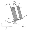
- Figures 1 and 2 show the device according to the invention in schematic side views in two different phases of the separation of a separator.
- a stack 1 of separator plates is held in a stack receptacle which is inclined with respect to the vertical and has a bottom 2 on its underside, on which the stack 1 rests, as well as at least one end guide rail 3 and two adjustable side guide rails 4.
- the rear side the stack holder is open to allow easy loading.
- a plate 5 which extends over the entire width of the stack receptacle and is in turn connected to the base 2 at its lateral ends (not shown), is fastened to the lower end of the end guide strip 3.
- the lower edge 5 'of the plate 5 is chamfered to the outside and delimits an outlet gap 6 for the bottom separator ⁇ ' of the stack with the bottom 2.
- the lower edge 5 ′ is in engagement with a stationary discharge roller 7, which is arranged below the plate 5 and is made of elastically deformable material, in particular of foam rubber, and extends over the length of the outlet gap 6.
- the top of the bottom 2 is slightly lower than that with the lower edge 5 'in one Grasping generators of the discharge roller 7 to ensure proper engagement of the bottom separator with the discharge roller, as will be explained below.
- the bottom separator 1 'of the stack 1 comes into contact with its front edge on the bevel of the bottom edge 5' and at the same time engages with the discharge roller 7. If the roller 7 is now rotated in the direction of the arrow by means of an intermittent rotary drive (not shown), the separator 1 'is carried along by the discharge roller 7, etc. This is because the friction between the discharge roller 7 and the lowermost separator 1 'is greater than between the lowermost separator 1' and the stack 1 above it. Since the lower edge 5 'acts on the discharge roller 7, the latter is removed when the separator 1' is carried along. compressed somewhat according to the thickness or profile thereof, as shown in FIG. 2.
- the discharge roller 7 is by means of a control device, not shown, which e.g. or the like via a light barrier scanning the rear edge of the separator. is operated, rotated in each discharge cycle until the separator has reached the area of a collecting tray 8 arranged in front of the discharge roller 7.
- a control device not shown, which e.g. or the like via a light barrier scanning the rear edge of the separator. is operated, rotated in each discharge cycle until the separator has reached the area of a collecting tray 8 arranged in front of the discharge roller 7.
- the diameter of the core of the discharge roller 7 and the layer of elastically compressible material arranged thereon are chosen such that the elastic layer is not completely compressed with no separator thickness.
- the plate 5 can be mounted for height adjustment in the direction of the double arrow P 'in FIG. 1 and for separating very thin separa gates, for example from 1 to 2 mm thick separator plates, are adjusted against the discharge roller 7 so that the lower edge 5 'of the plate 5 penetrates into the discharge roller 7 in order to ensure sufficient frictional entrainment of the separators.
- the base 2, to which the plate 5 is fastened can be adjustable towards and away from the stationary discharge roller 7 in the direction of the double arrow P in FIG. 1 in order to take different separator thicknesses into account.
- the above adjustment options are primarily intended for extreme cases, because the construction according to the invention allows the separating of separators within a relatively large range of thicknesses without the need for adjustment due to the compressibility of the discharge roller 7.
- the plate 5 sits at its lateral ends, not shown, on bolts projecting upwards from the base 2, which engage in corresponding openings in the plate 5, so that the plate 5 can be adjusted relative to the base and thus relative to the discharge roller 7.
Landscapes
- Sheets, Magazines, And Separation Thereof (AREA)
Abstract
Description
- Die Erfindung betrifft eine Vorrichtung zum Vereinzeln von in einem Stapel angeordneten plattenförmigen Separatoren für Akkumulatoren od.dgl., mit einer Führungsleisten aufweisenden, gegenüber der Vertikalen geneigt angeordneten Stapelaufnahme und einer im unteren Bereich derselben angeordneten Ausbringeinrichtung, wobei die stirnseitige Führungsleiste der Stapelaufnahme einen sich über die Breite der Stapelaufnahme erstreckenden unteren Abschnitt aufweist, der mit einem den Stapel abstützenden Boden der Stapelaufnahme einen Austrittsspalt für die Separatoren begrenzt, und wobei die Ausbringeinrichtung mit einer parallel zum Austrittsspalt verlaufenden Austragwalze aus elastisch verformbarem Material versehen ist.
- Es ist bereits eine Vorrichtung dieser Art bekannt (DE-A1-2 715 713), die in Verbindung mit einer Vorrichtung zum Umhüllen von Sammlerplatten mit wärmeverschweißbaren Separatoren angewendet wird. Bei dieser Vorrichtung werden die Separatoren mittels des pneumatisch oder hydraulisch hin- und herbewegbaren Bodens der Stapelaufnahme vereinzelt und zwischen zwei zusammenwirkende Förderwalzen bewegt, die mit Abstand vom Stapel angeordnet sind, weshalb auch eine mit der stirnseitigen Führungsleiste verbundene Plattenführung vorgesehen werden muß, die mit dem einen relativ großen Hub ausführenden Boden der Stapelaufnahme zusammenwirkt. Der Nachteil dieser Ausführung besteht vor allem darin, daß sie konstruktiv aufwendig und nur zum Vereinzeln von Separatoren einer bestimmten Stärke geeignet ist, was sich besonders dann als nachteilig erweist, wenn Separatoren mit einer vorbestimmten Profilierung vereinzelt werden sollen.
- Die Erfindung zielt nun darauf ab, eine Vorrichtung der einleitend angegebenen Art zu schaffen, die auf konstruktiv und steuerungstechnisch einfache Weise die Vereinzelung von Separatoren unterschiedlicher Stärke und Profilierung ermöglicht. Die erfindungsgemäße Vorrichtung zeichnet sich dadurch aus, daß der untere Abschnitt der stirnseitigen Führungsleiste der Stapelaufnahme mit einer von innen nach außen abgeschrägten Unterkante versehen ist, die mit der parallel zum Austrittsspalt verlaufenden Austragwalze, welche vorzugsweise aus Schaumgummi od.dgl. besteht, in Eingriff steht, wobei der untere Abschnitt der stirnseitigen Führungsleiste gegen die Austragwalze verstellbar ist.
- Mit dieser Vorrichtung, die mit geringen Kosten hergestellt werden kann sowie eine einfache und zuverlässige Betriebsweise ermöglicht, wird erreicht, daß Separatoren unterschiedlicher Stärke und Profilierung, d.h. z.B. glatte, mit Rippen versehene oder gewellte Separatoren, rasch und schonend vereinzelt werden können. Dabei kann die Vorrichtung nach Bedarf auf extreme Separatorstärken bzw. -ausbildungen durch Verstellung des unteren Abschnittes der stirnseitigen Führungsleiste gegen die Austragwalze hin verstellt werden. Für übliche Separatorplattenstärken ist diese Maßnahme nicht erforderlich, es reicht vielmehr aus, wenn die abgeschrägte Unterkante der stirnseitigen Führungsleiste die Austragwalze berührt, die dann beim Austragen des jeweils untersten Separators im Ausmaß der Stärke bzw. Profilierung des Separators zusammengedrückt wird.
- Bei einer bevorzugten Ausführungsform der Erfindung ist ferner der Abstand der Vorderkante des Bodens der Stapelaufnahme von der Austragwalze einstellbar, wobei außerdem der Boden der Stapelaufnahme mit dem unteren Abschnitt der stirnseitigen Führungsleiste verbunden sein kann. Auch diese Verstellung ist nur erforderlich, um bei extremen Separatorstärken eine einwandfreie Vereinzelung vornehmen zu können.
- Gemäß einer Weiterbildung der Erfindung ist die Stapelaufnahme an ihrer Hinterseite zum Einbringen des Stapels offen. Vorteilhaft ist somit zur Anpassung der Stapelaufnahme an unterschiedliche Stapelgrößen nur mehr die Verstellung von seitlichen Führungsleisten erforderlich.
- Die Erfindung wird nachfolgend an einem Ausführungsbeispiel unter Bezugnahme auf die Zeichnungen näher erläutert. Die
- Figuren 1 und 2 zeigen die erfindungsgemäße Vorrichtung in schematischen Seitenansichten in zwei verschiedenen Phasen der Vereinzelung eines Separators.
- Gemäß Figur 1 wird ein Stapel 1 von Separatorplatten in einer gegenüber der Vertikalen geneigt angeordneten Stapelaufnahme gehalten, die an ihrer Unterseite einen Boden 2 aufweist, auf welchem der Stapel 1 aufruht, sowie zumindest eine stirnseitige Führungsleiste 3 und zwei verstellbare seitliche Führungsleisten 4. Die Rückseite der Stapelaufnahme ist offen, um ein leichtes Beschicken derselben zu ermöglichen. Am unteren Ende der stirnseitigen Führungsleiste 3 ist eine sich über die gesamte Breite der Stapelaufnahme erstreckende Platte 5 befestigt, die ihrerseits an ihren seitlichen Enden (nicht gezeigt) mit dem Boden 2 verbunden ist. Die Unterkante 5' der Platte 5 ist nach außen abgeschrägt und begrenzt mit dem Boden 2 einen Austrittsspalt 6 für den jeweils untersten Separator η' des Stapels. Die Unterkante 5' steht mit einer unterhalb der Platte 5 angeordneten ortsfesten Austragwalze 7 aus elastisch verformbarem Material, insbesondere aus Schaumgummi, in Eingriff, die sich über die Länge des Austrittsspaltes 6 erstreckt. Die Oberseite des Bodens 2 liegt etwas tiefer als die mit der Unterkante 5' in Eingriff gelangende Erzeugende der Austragwalze 7, um einen einwandfreien Eingriff des jeweils untersten Separators mit der Austragwalze zu sichern, wie dies nachfolgend erläutert wird.
- Wie Figur 1 zeigt, gelangt der jeweils unterste Separator 1' des Stapels 1 mit seiner Vorderkante an der Abschrägung der Unterkante 5' zur Anlage und zugleich mit der Austragwalze 7 in Eingriff. Wird nun die Walze 7 mittels eines nicht gezeigten, intermittierenden Drehantriebes in der Pfeilrichtung gedreht, so wird der Separator 1' von der Austragwalze 7 mitgenommen, u.zw. deshalb, weil die Reibung zwischen der Austragwalze 7 und dem untersten Separator 1' größer ist als zwischen dem untersten Separator 1' und dem darüberliegenden Stapel 1. Da die Unterkante 5' an der Austragwalze 7 angreift, wird diese bei der Mitnahme des Separators l' entsprechend der Stärke oder Profilierung desselben etwas zusammengedrückt, wie dies Figur 2 zeigt.
- Die Austragwalze 7 wird mittels einer nicht gezeigten Steuereinrichtung, die z.B. über eine die hintere Kante des Separators abtastende Lichtschranke od.dgl. betätigt wird, in jedem Austragzyklus jeweils so lange gedreht, bis der Separator in den Bereich einer vor der Austragwalze 7 angeordneten Auffangschale 8 gelangt ist.
- Die Durchmesser des Kernes der Austragwalze 7 und der auf diesem angeordneten Schicht aus elastisch zusammendrückbarem Material werden so gewählt, daß die elastische Schicht bei keiner Separatorstärke vollständig zusammengedrückt wird.
- Das erläuterte Ausführungsbeispiel kann im Rahmen des allgemeinen Erfindungsgedankens verschiedentlich abgewandelt werden. So kann die Platte 5 für sich in Richtung des Doppelpfeiles P' in Figur 1 höhenverstellbar montiert sein und zur Vereinzelung sehr dünner Separatoren, z.B. von 1 bis 2 mm dicken Separatorplatten, gegen die Austragwalze 7 hin so nachgestellt werden, daß die Unterkante 5' der Platte 5 in die Austragwalze 7 eindringt, um eine ausreichende Reibungsmitnahme der Separatoren zu gewährleisten. Ferner kann der Boden 2, an welchem die Platte 5 befestigt ist, gegen die ortsfeste Austragwalze 7 hin und von dieser weg in Richtung des Doppelpfeiles P in Figur 1 verstellbar sein, um unterschiedlichen Separatorstärken Rechnung zu tragen. Die vorstehenden Verstellmöglichkeiten sind vor allem für Extremfälle bestimmt, denn die erfindungsgemäße Konstruktion gestattet infolge der Zusammendrückbarkeit der Austragwalze 7 die Vereinzelung von Separatoren innerhalb eines relativ großen Stärkenbereiches ohne das Erfordernis einer Verstellung. Zweckmäßig sitzt die Platte 5 an ihren nicht gezeigten seitlichen Enden auf vom Boden 2 nach oben ragenden Bolzen, die in entsprechende Öffnungen in der Platte 5 eingreifen, so daß die Platte 5 gegenüber dem Boden und somit relativ zur Austragwalze 7 eingestellt werden kann.
Claims (4)
Applications Claiming Priority (2)
| Application Number | Priority Date | Filing Date | Title |
|---|---|---|---|
| AT0020283A AT381809B (de) | 1983-01-21 | 1983-01-21 | Vorrichtung zum vereinzeln von in einem stapel angeordneten plattenfoermigen separatoren, beispielsweise fuer akkumulatoren |
| AT202/83 | 1983-01-21 |
Publications (3)
| Publication Number | Publication Date |
|---|---|
| EP0114801A2 true EP0114801A2 (de) | 1984-08-01 |
| EP0114801A3 EP0114801A3 (en) | 1986-09-10 |
| EP0114801B1 EP0114801B1 (de) | 1988-05-11 |
Family
ID=3484192
Family Applications (1)
| Application Number | Title | Priority Date | Filing Date |
|---|---|---|---|
| EP84890016A Expired EP0114801B1 (de) | 1983-01-21 | 1984-01-20 | Vorrichtung zum Vereinzeln von in einem Stapel angeordneten plattenförmigen Separatoren für Akkumulatoren oder dergleichen |
Country Status (3)
| Country | Link |
|---|---|
| EP (1) | EP0114801B1 (de) |
| AT (1) | AT381809B (de) |
| DE (1) | DE3471080D1 (de) |
Cited By (3)
| Publication number | Priority date | Publication date | Assignee | Title |
|---|---|---|---|---|
| GB2183221A (en) * | 1985-11-25 | 1987-06-03 | Cubic Western Data | Ticket magazine module |
| EP0402348A1 (de) * | 1989-06-06 | 1990-12-12 | JUNGFER AKKUMULATOREN GmbH | Magazin für Akkumulatorenplatten |
| CN103387070A (zh) * | 2013-07-10 | 2013-11-13 | 超威电源有限公司 | 一种蓄电池自动放隔挡纸装置 |
Families Citing this family (1)
| Publication number | Priority date | Publication date | Assignee | Title |
|---|---|---|---|---|
| WO2006015430A1 (en) * | 2004-08-09 | 2006-02-16 | The Australian National University | Solar cell (sliver) sub-module formation |
Family Cites Families (6)
| Publication number | Priority date | Publication date | Assignee | Title |
|---|---|---|---|---|
| AT225504B (de) * | 1961-06-05 | 1963-01-25 | Metallwaren & Maschf P Schwarz | Vorrichtung zum Vereinzeln von in einem Vorratsschacht magazinierten Metall-Stanzplatinen od. dgl. |
| DE1929172A1 (de) * | 1969-06-09 | 1971-01-07 | Hadi Offermann Maschb Gmbh | Vorrichtung zum Vereinzeln von Akkumulator-Platten aus einem Stapel |
| DE2203626C2 (de) * | 1972-01-26 | 1983-03-03 | Kleindienst Gmbh & Co Kg, 8900 Augsburg | Vorrichtung zur Entnahme von Blättern aus einem Hauptstapel |
| AT329124B (de) * | 1974-06-26 | 1976-04-26 | Aga Elbak Batteriewerke Ges M | Vorrichtung zur einzelentnahme von separatoren fur akkumulatoren aus stapeln |
| US4026000A (en) * | 1976-07-15 | 1977-05-31 | Globe-Union Inc. | Apparatus for producing enveloped battery plates |
| DE3003555A1 (de) * | 1980-01-31 | 1981-08-06 | Hornberger Maschinenbaugesellschaft mbH & Co KG, 7294 Schopfloch | Vorrichtung zum zufuehren von streifenmaterial an einer kantenanleimmaschine |
-
1983
- 1983-01-21 AT AT0020283A patent/AT381809B/de not_active IP Right Cessation
-
1984
- 1984-01-20 EP EP84890016A patent/EP0114801B1/de not_active Expired
- 1984-01-20 DE DE8484890016T patent/DE3471080D1/de not_active Expired
Cited By (3)
| Publication number | Priority date | Publication date | Assignee | Title |
|---|---|---|---|---|
| GB2183221A (en) * | 1985-11-25 | 1987-06-03 | Cubic Western Data | Ticket magazine module |
| EP0402348A1 (de) * | 1989-06-06 | 1990-12-12 | JUNGFER AKKUMULATOREN GmbH | Magazin für Akkumulatorenplatten |
| CN103387070A (zh) * | 2013-07-10 | 2013-11-13 | 超威电源有限公司 | 一种蓄电池自动放隔挡纸装置 |
Also Published As
| Publication number | Publication date |
|---|---|
| DE3471080D1 (en) | 1988-06-16 |
| ATA20283A (de) | 1986-04-15 |
| EP0114801B1 (de) | 1988-05-11 |
| EP0114801A3 (en) | 1986-09-10 |
| AT381809B (de) | 1986-12-10 |
Similar Documents
| Publication | Publication Date | Title |
|---|---|---|
| DE3047436C2 (de) | ||
| DE2808617C2 (de) | Verfahren und Anlage zum Ausrichten von stapel- oder reihenförmigen Gruppen von Gegenständen | |
| CH647976A5 (de) | Vorrichtung zum vereinzeln von gestapelten zuschnitten aus karton, pappe oder wellpappe. | |
| DE2742063C3 (de) | Filterplattenöffnungsmechanismus | |
| DE2737933B2 (de) | Gehäuse für ein Gerät, insbesondere für einen Drucker | |
| DE3423119A1 (de) | Vorrichtung zum verlegen eines gummiartigen streifenfoermigen dichtungsprofils in dehnungsfugen von fahrbahnen | |
| DE2627810C3 (de) | Vorrichtung zum Vereinzeln, Transportieren und Ablegen von Vergütungsbögen im Zuge der Herstellung von vergüteten Spanplatten, Faserplatten o.dgl | |
| DE3318314A1 (de) | Vorrichtung zum trennen der einzelnen zuschnitte eines stapels gestanzter blaetter | |
| EP0167982B1 (de) | Stauchfalzmaschine mit einer Falzgutaufreihvorrichtung | |
| DE3033334A1 (de) | Vorrichtung zum herstellen von laenglichen konstruktionsteilen | |
| EP0114801B1 (de) | Vorrichtung zum Vereinzeln von in einem Stapel angeordneten plattenförmigen Separatoren für Akkumulatoren oder dergleichen | |
| DE2166212C3 (de) | Scharnierbandförderer für Metallspäne. Ausscheidung aus: 2100932 | |
| DE1964572A1 (de) | Filmschneidevorrichtung | |
| DE69206418T2 (de) | Schottentüranordnung. | |
| EP0097855A1 (de) | Plattenfilter | |
| DE9301072U1 (de) | Sammelvorrichtung für Blätter zur Bildung von Blattstapeln | |
| EP0175795A2 (de) | Kaschierstation | |
| DE3823705A1 (de) | Vorrichtung zum vereinzeln von zuschnitten aus einem stapel | |
| DE4432124C2 (de) | Vorrichtung zum Vereinzeln von Zeitschriften-Remittenden von der Unterseite eines Stapels | |
| DE2747623C2 (de) | Vorratsmagazin mit einer Vorrichtung zur Entnahme jeweils eines einzelnen Filmblattes | |
| DE9208033U1 (de) | Zuführeinrichtung zum Vereinzeln von Zuschnitten | |
| DE68909791T2 (de) | Vorrichtung zum verbinden von zwei materialbahnen. | |
| DE29520112U1 (de) | Vorrichtung zum Trennen und seitlichem Auslenken durch Längsschnitt erzeugten Metallstreifen | |
| DE2643388B2 (de) | Vorrichtung zum Vereinzeln von Blättern eines Stapels | |
| DE2230631C3 (de) | Verfahren zum Herstellen quaderförmiger Schachteln |
Legal Events
| Date | Code | Title | Description |
|---|---|---|---|
| PUAI | Public reference made under article 153(3) epc to a published international application that has entered the european phase |
Free format text: ORIGINAL CODE: 0009012 |
|
| AK | Designated contracting states |
Designated state(s): BE CH DE FR GB IT LI LU NL SE |
|
| PUAL | Search report despatched |
Free format text: ORIGINAL CODE: 0009013 |
|
| AK | Designated contracting states |
Kind code of ref document: A3 Designated state(s): BE CH DE FR GB IT LI LU NL SE |
|
| 17P | Request for examination filed |
Effective date: 19861117 |
|
| 17Q | First examination report despatched |
Effective date: 19870806 |
|
| GRAA | (expected) grant |
Free format text: ORIGINAL CODE: 0009210 |
|
| AK | Designated contracting states |
Kind code of ref document: B1 Designated state(s): BE CH DE FR GB IT LI LU NL SE |
|
| GBT | Gb: translation of ep patent filed (gb section 77(6)(a)/1977) | ||
| REF | Corresponds to: |
Ref document number: 3471080 Country of ref document: DE Date of ref document: 19880616 |
|
| ITF | It: translation for a ep patent filed | ||
| ET | Fr: translation filed | ||
| PLBE | No opposition filed within time limit |
Free format text: ORIGINAL CODE: 0009261 |
|
| STAA | Information on the status of an ep patent application or granted ep patent |
Free format text: STATUS: NO OPPOSITION FILED WITHIN TIME LIMIT |
|
| 26N | No opposition filed | ||
| ITTA | It: last paid annual fee | ||
| EPTA | Lu: last paid annual fee | ||
| PGFP | Annual fee paid to national office [announced via postgrant information from national office to epo] |
Ref country code: DE Payment date: 19940308 Year of fee payment: 11 |
|
| PGFP | Annual fee paid to national office [announced via postgrant information from national office to epo] |
Ref country code: CH Payment date: 19941220 Year of fee payment: 12 |
|
| PGFP | Annual fee paid to national office [announced via postgrant information from national office to epo] |
Ref country code: FR Payment date: 19941228 Year of fee payment: 12 |
|
| PGFP | Annual fee paid to national office [announced via postgrant information from national office to epo] |
Ref country code: LU Payment date: 19950101 Year of fee payment: 12 |
|
| PGFP | Annual fee paid to national office [announced via postgrant information from national office to epo] |
Ref country code: GB Payment date: 19950110 Year of fee payment: 12 |
|
| PGFP | Annual fee paid to national office [announced via postgrant information from national office to epo] |
Ref country code: SE Payment date: 19950117 Year of fee payment: 12 |
|
| PGFP | Annual fee paid to national office [announced via postgrant information from national office to epo] |
Ref country code: BE Payment date: 19950130 Year of fee payment: 12 |
|
| EAL | Se: european patent in force in sweden |
Ref document number: 84890016.3 |
|
| PGFP | Annual fee paid to national office [announced via postgrant information from national office to epo] |
Ref country code: NL Payment date: 19950131 Year of fee payment: 12 |
|
| PG25 | Lapsed in a contracting state [announced via postgrant information from national office to epo] |
Ref country code: DE Effective date: 19951003 |
|
| PG25 | Lapsed in a contracting state [announced via postgrant information from national office to epo] |
Ref country code: LU Free format text: LAPSE BECAUSE OF NON-PAYMENT OF DUE FEES Effective date: 19960120 Ref country code: GB Effective date: 19960120 |
|
| PG25 | Lapsed in a contracting state [announced via postgrant information from national office to epo] |
Ref country code: SE Effective date: 19960121 |
|
| PG25 | Lapsed in a contracting state [announced via postgrant information from national office to epo] |
Ref country code: CH Effective date: 19960131 Ref country code: BE Effective date: 19960131 Ref country code: LI Effective date: 19960131 |
|
| BERE | Be: lapsed |
Owner name: AKKUMULATORENFABRIK DR. LEOPOLD JUNGFER Effective date: 19960131 |
|
| PG25 | Lapsed in a contracting state [announced via postgrant information from national office to epo] |
Ref country code: NL Effective date: 19960801 |
|
| GBPC | Gb: european patent ceased through non-payment of renewal fee |
Effective date: 19960120 |
|
| REG | Reference to a national code |
Ref country code: CH Ref legal event code: PL |
|
| PG25 | Lapsed in a contracting state [announced via postgrant information from national office to epo] |
Ref country code: FR Effective date: 19960930 |
|
| NLV4 | Nl: lapsed or anulled due to non-payment of the annual fee |
Effective date: 19960801 |
|
| EUG | Se: european patent has lapsed |
Ref document number: 84890016.3 |
|
| REG | Reference to a national code |
Ref country code: FR Ref legal event code: ST |