EP0114460A2 - Bandage pneumatique ayant une ceinture à différent module - Google Patents
Bandage pneumatique ayant une ceinture à différent module Download PDFInfo
- Publication number
- EP0114460A2 EP0114460A2 EP83306153A EP83306153A EP0114460A2 EP 0114460 A2 EP0114460 A2 EP 0114460A2 EP 83306153 A EP83306153 A EP 83306153A EP 83306153 A EP83306153 A EP 83306153A EP 0114460 A2 EP0114460 A2 EP 0114460A2
- Authority
- EP
- European Patent Office
- Prior art keywords
- band
- modulus
- annular
- tire
- radially
- Prior art date
- Legal status (The legal status is an assumption and is not a legal conclusion. Google has not performed a legal analysis and makes no representation as to the accuracy of the status listed.)
- Withdrawn
Links
Images


Classifications
-
- B—PERFORMING OPERATIONS; TRANSPORTING
- B60—VEHICLES IN GENERAL
- B60C—VEHICLE TYRES; TYRE INFLATION; TYRE CHANGING; CONNECTING VALVES TO INFLATABLE ELASTIC BODIES IN GENERAL; DEVICES OR ARRANGEMENTS RELATED TO TYRES
- B60C9/00—Reinforcements or ply arrangement of pneumatic tyres
- B60C9/18—Structure or arrangement of belts or breakers, crown-reinforcing or cushioning layers
-
- B—PERFORMING OPERATIONS; TRANSPORTING
- B60—VEHICLES IN GENERAL
- B60C—VEHICLE TYRES; TYRE INFLATION; TYRE CHANGING; CONNECTING VALVES TO INFLATABLE ELASTIC BODIES IN GENERAL; DEVICES OR ARRANGEMENTS RELATED TO TYRES
- B60C17/00—Tyres characterised by means enabling restricted operation in damaged or deflated condition; Accessories therefor
Definitions
- This invention relates to banded radial run-flat tires and, more particularly, to banded tires having a dual-modulus of stiffness band for enhancing the performance of the tire in the deflated or partially inflated condition.
- a run-flat tire is one designed to support a vehicle for operation even if the tire has partially or totally lost its inflation pressure.
- the advantages of such a tire in safety, convenience, and cost are obvious.
- the elimination of the require ment for a spare wheel and tire results in a weight and space savings for the vehicle itself that achieves a long-sought goal in the industry.
- a recent successful development in the art of run-flat tires is the band-reinforced radial tire invented by one of the inventors in the present application, which banded tire is the subject of U.S. patent No. 4,111,249, assigned to the assignee of the present invention.
- the types of run-flat tires with which the dual modulus band of the subject invention can be used are disclosed in that Markow patent, U. S . No. 4,111,249, whic 6 b is hereby incorporated herein by reference.
- the banded run-flat tire is a pneumatic radial tire having a casing with a crown and sidewalls.
- the sidewalls extend radially inward from the crown on either side to annular beads which, in a conventional way, are used to mount the tire in a sealed relationship on the rim of a wheel.
- the band element is incorporated circumferentially in the crown region of the tire radially inwardly from the tread thereof. Any suitabl high-strength material can be used for the band, preferably the band is a thin structural ring fabricated from a fiber/epoxy composite.
- Radial tires as is well known, have a multiplicity of closely spaced radial reinforcing cords or wires in the sidewalls.
- the radial cords or wires function as spoke-like reinforcing elements to stabilize the circumferentially extending band.
- the radial spoke-like elements and the band stabilized thereby form a load- sustaining structure analogous to an elastic arch.
- the band receives vertical, drag, and side loads from the road or ground surface. These loads are carried in compression and bending, with the spoke-like radial elements acting as tension members to support the axle.
- a further important function of the closely spaced radial elements is to stabilize the band against buckling.
- the band when operating with the tire normally inflated, the band should not interact adversely with the tire.
- a tire and its band in operation maintain a substantially cylindrical shape except for a flattening at the footprint or the sector of the tire in contact with the surface.
- the tire In the inflated condition, the tire has a relatively small footprint where the tire and the band flattens in contact with the surface and there is a gradual bend in the transition zone at the leading and trailing edges of the footprint between the flattened portion and the normally cylindrical portion of the tire. It will be seen that a particular segment of the band (and tire) will be subject, therefore, to a cycle of bending twice during each revolution of the tire as that segment passes through the transition zones on either side of the footprint. It is also in the footprint area that most of the unpredictable transient loads caused by road surface anomalies occur.
- the present invention relates to a banded radial run-flat tire having a dual-modulus of stiffness band.
- banded radial run-flat tires are disclosed in the Markow patent, U.S. No. 4,11.1,249, referenced previously herein.
- the bands disclosed in that Markow patent have a constant modulus providing a classic linear load/deflection relationship when the band bends in operation.
- the bands preferably are fabricated from fiber/resin composites which are laid up or fabricated using filament winding techniques.
- a dual modulus behavior is achieved in the bands in several of those embodiments by the use of techniques involving the increasing of filament tension in the later stages of the winding process.
- Pre-stressing filament wound structural elements such as pressure vessels and pipes by the use of means such as expandible mandrels is well known in the prior art.
- the prior art teachings of pre-stressing techniques are directed to static structures rather than to the attainment of a dual-modulus bending behavior in a dynamic flexible annular band structure which undergoes large cyclic bending deflections as an inherent aspect of its operation.
- Pre-stressing techniques for the cords or plies of tires are also known in the prior art.
- the techniques include the use of greater tension or extensibility of various cords or plies with respect to other cords or plies in the carcass or breaker strips or belts of conventional un-banded tires.
- Representative examples of such teachings are disclosed in French patent of addition 11,179 (1910), British 758,914, and U.S. patent Nos. 2,198,586, and 2,990,870. It will be seen that these prior art patents are addressed to details of carcass ply configurations which are intended to equalize the stress distribution in operatio in loaded, inflated tires.
- This invention is a banded radial run-flat tire, the band of which has a dual-modulus of bending deflection.
- Bands having three types of dual-modulus bending characteristics are disclosed.
- the band In the first type of dual-modulus band, the band is designed so that it has a greater resistance to bending forces tending to decrease its local radius of curvature than to those tending to flatten it.
- bending stiffness increases with increasing stress irrespective of the bending direction.
- the design produces a two-step modulus in which initial deflection is resisted at one rate and final deflection at another rate.
- the band is constructed with a radially outward substantiall solid circumferential'section and a radially inward circumferential section provided with discontinuities such as transverse slits around its inside periphery.
- the discontinuities allow the band to resist compression such as would be involved in forces tending to reduce the radius of the band, but not to tension acting to flatten a sector of the band.
- a second embodiment for achieving a favorable variation in stiffness with bending direction has a thin band to which are attached standoff shear ties around the outer diameter.
- shear ties are connected to one another by thin fibers in an arrangement in which the fibers resist tensile loads on the band but which buckle when reverse bending puts them in compression.
- a third embodiment exhibiting variation in stiffness with bending direction has a thin band on the outside periphery of which are attached transversely corrugated strips. Attached to each trough of the corrugated strips is a radial strut With this arrangement, compression loads tending to decrease the radius of the band are resisted by the struts, but tensile loads tending to flatten the band are not resisted.
- a fourth embodiment having this first type of dual-modulus exploits a band having an anticlastic shape.
- the band has an arcuate cross-section with an outwardly concave configuration. Under load, the arcuate cross-section will deform so as to have a lower section modulus where the band flattens out and a more stable section mod ulus due to elastic buckling where the band radius of curvature is decreasing.
- a further embodiment has a thin flat band having a plurality of coaxial rings of anticlastic configuration fastened side-by-side on the outside periphery of the band. In operation, each of the anticlastic rings will behave in the manner describei for the previous embodiment.
- the band s fabricated out of various composite materials whose elastic properties are different in tension and in compression, the materials being arranged selectively in coaxial thicknesses.
- a thickness of material whose modulus is relatively lower in compression would be placed toward the outside diameter of the band.
- bands having the second type of dual-modulus behavior in which bending stiffness is increased with increasing stress are disclosed.
- One embodiment of this type of dual-modulus band has an elastomeric filler material sandwiched between coaxial inner and outer annular band elements, forming a structure analogous to a beam with the elastomeric material acting as the web of the beam and the annular elements the caps of the beam.
- the caps are connected with discrete tensile fibers which are embedded in the elastomeric filler, which is of a type designed to work best in compression.
- a further embodimen of this type of dual-modulus structure has a thin annular band to which are attached standoff shear ties around the inner and outer diameter- These shear ties are connected to one another by thin curved fibers in an arrangement in which the curved fibers on the side opposite the direction of bending straighten under load such that the band stiffens with increased stress and deflection.
- a dual-modulus behavior of the band of the run-flat tire is obtained with a filament-wound band in which the outer filaments are pre-stressel.
- a filament-wound band by proper design, including a judicious choice of materials of construction, and control of the manufacturing process, any one of the three types of dual-modulus bending characteristics can be achieved by the use of a pre-stress ing technique.
- the technique during filament winding around a cylindrical mandrel, the initial layers are laid down with low filament tension. In subsequent layers, filament winding tension is increased either in one large step or in a programmed series of smaller steps.
- a band fabricated with a pre-stress technique has a relatively low bending modulus in a direction flattening out the band until the inner surface micro-wrinkles straighten, whereupon the band stiffens to resist overbending.
- overbending can be caused by impacting a pothol or a small obstacle.
- the pre-stresses add to the induced stresses, causing the band to become stiff relatively early in its bending response.
- the -band With a bending direction-dependent dual-modulus band of the invention, the -band can be stiff enough for proper run-flat tire operation and yet lower repeated stresses in the ground contact area are developed. Where band bending modulus is directly but not necessarily linearly, proportional to applied load, the band can be made thinner and lighter. It will still provide prope support when running flat but will have relatively little influenc on pressurized operation.
- Another object of the invention is to provide a band for a banded run-flat tire in which the bending stiffness of the band in a direction tending to flatten the tire has a constant or multi-step increase with deflection and in which the bending stiffness in the opposite direction remains constant with deflection.
- a yet further object of the invention is to provide a banded run-flat tire at reasonable cost in which tire the band stresses are within the fatigue limits for both pressurized and unpressurized operation with sufficient margin to accommodate high transient ground impact loads and yet in which the band stiffness is sufficient to accept a proper proportion of structura support during run-flat operation.
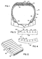
- F ig. 1 illustrates an embodiment of a tire 10 of the invention mounted on a wheel 12 which may be of a conventional type having a drop-center rim 14 welded to a wheel body 16.
- Tire 10 comprises a carcass or casing 18 having an outer pheripheral tread portion 20 in the crown 22 of the casing and sidewalls 24 extending from either side of the crown to beads 26 in the inside peripheral portions of the sidewalls. Treads 28 in any desired pattern can be incised in tread portion 20 of the casing 18.
- Beads 26, which can be reinforced with the usual annular cords or wires 30, are adapted to seat in an airtight relationship in the rim 14 when the tire is mounted on the wheel 12.
- the sidewalls 24 of the casing are reinforced by the usual known weftless radial plies or elements 32.
- Radial elements 32 can be fabricated out of steel wires or suitable textile fibers as is well known in the art.
- annular compression element or band 36 Located in the crown of the radial tire just described underlying the tread thereof is an annular compression element or band 36.
- Band 36 is reinforced and stabilized by the radial elements 32 in sidewalls 24 to give tire 10 its run-flat capabilities.
- tire 10 When mounted on the wheel 12, tire 10 can be inflated through the usual valve (not shown) in the rim of the wheel.
- the band 36 has dual-modulus of bending characteristics.
- bands having three types of dual-modulus characteristics can be used in the tire of this invention.
- the first type of dual-modulus band it is designed so that it has a greater resistance to bending forces tending to decrease its local radius of curvature than to those tending to flatten it.
- a dual-modulus band 36 1 of the first type is shown in Figs. 2-4.
- dual-modulus band 36 1 has a radially outward, substantially solid annular body section 38 and a radially inward circumferential body section 40.
- Inward body section 40 is provided with a series of discontinuities such as transverse slots 42 which separate the inward body into a memori of lands 44 around the inside circumference of annular body sectio 36 with the slots 42 between them.
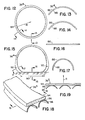
- band 36 2 has a thin annular band element 50 having a multiplicity of standoff shear ties, such as the V-shaped members 52, attached in discrete annular rows 54, 56, 58, and 60, for example, around the outer periphery 62 of the band element.
- the apexes 63 of the shear ties in each row are connected to one another by annular fibers 64.
- the tension on the annular fibers 64 is relieved and the flattening is resisted only by the resiliency of the band element 50 itself (Fig. 6).
- the annular fibers 64 are put into tension and straighten out (Fig. 7 ) Further deflection of the band is resisted by the band and annular fiber in tension.
- FIGs 8-11 illustrate a further embodiment of the dual-modulus band of the invention.
- the band 36 3 has a thin annular band element 66 having a number of transversely corrugated annular strips 68 attached side-by-side (Fig. 9) at the crests 70 of their corrugations to the band element 66 around the outer periphery 72 thereof.
- Attached to the inside surface 74 of each of the troughs 76 of the corrugated strips 68 is a radial strut 78.
- Each of the struts 78 can have a flange or buffer strip 80 on its radially inward free end 82.
- the band 36 4 has a band element 86 with an annular anticlastic shape; i.e., the structure has opposite curvatures at any given point.
- the band 36 4 is an annular structure made from a sheet material and having, in the unstressed condition, an arcuate cross-section with concave surface 88 facing radially outward, as shown in Figs. 13 and 14.
- band 36 5 comprises a band element 94 having a number of annular anticlastic elements 96 afixed side-by-side on the outside peripheral surface 98 of the band element.
- Each of the anticlastic elements 96 is made from a sheet material and, in the unstressed condition, has an arcuate cross-section with a concave surface facing radially outwardly.
- the behavior of anticlastic elements 96 will substantially correspond collectively to that of the single anticlastic element 86 of band 36 4 .
- a further description thereof will serve no useful purpose and such will not be given.
- the various materials used can be arranged in a predetermine sequence of coaxial layers or thicknesses.
- the material having a modulus lower in compression will be situated toward the outside diameter of the band.
- a candidate material for use in the outside region of the band is Kevlar (an aramid marketed by DuPont Company).
- the micro-structure of Kelvar would cause it to act in a low-modulus manner if, in the fabrication of the band, hoopwise fibers of Kelvar are embedded in a matrix having a low modulus.
- the inside layers or thicknesses of the band can be fabricated out of glass fibers in an epoxy resin matrix.
- a second type of dual-modulus band behavior attainable in this invention is characterized by a bending stiffness which increases in either direction with increasing applied load.
- An embodiment of that type of band is illustrated in Figs. 20-22.
- the dual-modulus band 36 6 comprises a pair of thin annular elements 108 and 110 having an elastomeric filler material 112 sandwiched between them.
- thi arrangement forms a structure analogous to a beam with the elastomeric material acting as the web of the beam and the annulai elements the caps of the beam.
- a multiplicity of discrete tensil fibers 114 connect the outside surface 116 of inner annular element 108 with the inside surface 118 of the outer annular element 110. It will be appreciated that the individual fibers are completely surrounded by the elastomeric filler 112..
- the elastomer is one selected for its favorable properties in compression.
- the annular band elements 108 and 110 In operation in the unstressed condition, the annular band elements 108 and 110 have a circular shape and the fibers 114 will be oriented radially and thus will not impose any stresses on the elastomeric material 112 surrounding them (Fig.20). Should a load be imposed that reduces the radius of curvature R of band 36 6 , the consequent differential movement of the outer annular element relative to the inner annular element puts the fibers into diagonal tension. This puts the elastomeric material into compression and the beam stiffness increases proportionately as the diagonal tension angle increases (Fig. 21). Should the load tend to flatten the band, the relative movement between the annular elements puts the fibers into diagonal tension in the opposite direction as shown in Fig. 22 to again put the elastomeric material into compression and the beam stiffness will again increase proportionally with band deflection.
- a preferred embodiment of the dual-modulus band of the invention employs a filament wound structure.
- the inner filament layers of the band are put into compression by the outer layers.
- This compression of the inner layers can be achieved by winding the band on a cylindrical mandrel with a compressible outer surface.
- the cylindrical mandrel 132 has its outer diametrical surface 134 coated with an elastomeric material 136.
- a progressive increase in winding tension using a conventional filament winding mandrel can be employed to produce a band having a dual-modulus behavior.
- the first layers of filaments are wound on the mandrel with just enough tension to cause them to lie flat.
- the filament tension is increased controllably and in a reproducible manner either in one large step or in a programmed series of smaller steps.
- the final layers are wound with considerable tension and the ends are secured to maintain this tension and the resulting compression in the band is locked in during the curing phase of fabrication.
- Fiberglas or E Glass filaments in a resin matrix with a nominal filament/ resin ratio of about 60/40 are suitable for use.
- resin formulations suitable for use is one using about 4.5 lbs of EPON 828, 4.0 lbs of methyl nadic anhydride, 0.05 lb benzyl di-methyl amine, 0.25 lb of KELPOXY G 272-100, and 0.25 lb KELPOXY G 293-100; or another formulation using about 4.0 lbs EPON 828, 4.0 lbs methyl nadic anhydride, 0.05 lb benzyl di-methyl amine, 0.5 lb KELPOXY G 272-100, and 0.5 lb KELPOXY G 293-100.
- any suitable known technique for integrating the filaments and the resin can be employed- As is well known in the art, curing of the resin can be carried out at any suitable temperature for any suitable time, as, for example; at 325F for 4 hr; or 325F for 4 hr and 400F for 4 hr; or at 325F for 4 hr plus the tire cure cycle.
- the critical element is the pre-stressing of the outer filament layers of the band.
- the annular fibers 64 that are normally straight in the unstressed condition of the band can be curved initially.
- the band is not as stiff as it is later on when the annular fiber tensile elements become straight.
Landscapes
- Engineering & Computer Science (AREA)
- Mechanical Engineering (AREA)
- Tires In General (AREA)
- Tyre Moulding (AREA)
Applications Claiming Priority (2)
| Application Number | Priority Date | Filing Date | Title |
|---|---|---|---|
| US460492 | 1983-01-24 | ||
| US06/460,492 US4456048A (en) | 1983-01-24 | 1983-01-24 | Dual-modulus band banded tire |
Publications (2)
| Publication Number | Publication Date |
|---|---|
| EP0114460A2 true EP0114460A2 (fr) | 1984-08-01 |
| EP0114460A3 EP0114460A3 (fr) | 1985-07-10 |
Family
ID=23828928
Family Applications (1)
| Application Number | Title | Priority Date | Filing Date |
|---|---|---|---|
| EP83306153A Withdrawn EP0114460A3 (fr) | 1983-01-24 | 1983-10-12 | Bandage pneumatique ayant une ceinture à différent module |
Country Status (6)
| Country | Link |
|---|---|
| US (1) | US4456048A (fr) |
| EP (1) | EP0114460A3 (fr) |
| JP (1) | JPS59137204A (fr) |
| AU (1) | AU562255B2 (fr) |
| CA (1) | CA1207645A (fr) |
| DE (1) | DE114460T1 (fr) |
Cited By (5)
| Publication number | Priority date | Publication date | Assignee | Title |
|---|---|---|---|---|
| EP0191124A1 (fr) * | 1983-07-27 | 1986-08-20 | Jonny Janus | Pneumatique à ceinture et son procédé de fabrication |
| EP0205356A2 (fr) * | 1985-06-06 | 1986-12-17 | Grumman Aerospace Corporation | Pneumatique de sécurité comportant une ceinture obtenue par enroulement hélicoidal |
| AT386571B (de) * | 1985-12-11 | 1988-09-12 | Semperit Ag | Fahrzeugluftreifen |
| EP0394536A1 (fr) * | 1989-04-28 | 1990-10-31 | Hille + Müller Kg | Pneumatique à ceinture pour roue de véhicule |
| US6260593B1 (en) | 1998-08-04 | 2001-07-17 | Bridgestone/Firestone Research, Inc. | Race tire containing band element |
Families Citing this family (38)
| Publication number | Priority date | Publication date | Assignee | Title |
|---|---|---|---|---|
| US4708186A (en) * | 1983-01-24 | 1987-11-24 | Grumman Aerospace Corporation | Segmented-band banded tire |
| AT384191B (de) * | 1984-08-23 | 1987-10-12 | Semperit Ag | Fahrzeugluftreifen |
| US4734144A (en) * | 1985-04-25 | 1988-03-29 | Grumman Aerospace Corporation | Banded-tire building method |
| AT387933B (de) * | 1985-09-02 | 1989-04-10 | Semperit Ag | Fahrzeugluftreifen |
| FR2614956B1 (fr) * | 1987-05-05 | 1989-08-18 | Renault | Dispositif actif permettant de faire varier la raideur d'elements de suspension, notamment pour vehicules automobiles |
| US5201971A (en) * | 1989-04-19 | 1993-04-13 | Pipelli Armstrong Tire Corporation | Pneumatic tires containing a composite belt |
| US5035792A (en) * | 1990-11-19 | 1991-07-30 | Uop | Cleanup of hydrocarbon-conversion system |
| US5817197A (en) * | 1996-10-15 | 1998-10-06 | Bridgestone/Firestone, Inc. | Multiple link tire belt |
| US5879484A (en) * | 1997-01-13 | 1999-03-09 | Bridgestone/Firestone, Inc. | Run flat banded pneumatic tire |
| US6598634B1 (en) | 1998-04-08 | 2003-07-29 | Bridgestone Corporation | Cured tire including encapsulated high modulus composite |
| US6117258A (en) * | 1998-04-27 | 2000-09-12 | Bridgestone/Firestone Research, Inc. | Band element and method for building same for a run flat banded tire |
| US6148885A (en) | 1998-07-21 | 2000-11-21 | Bridgestone/Firestone Research, Inc. | Pneumatic tire with band element |
| US6112791A (en) | 1998-12-17 | 2000-09-05 | Bridgestone/Firestone Research, Inc. | Pneumatic tire with band element having tapered end portions |
| US6695025B1 (en) | 1999-05-18 | 2004-02-24 | The Goodyear Tire & Rubber Company | Runflat tire construction with ply cords having a variable modulus of elasticity |
| US7418988B2 (en) * | 1999-12-10 | 2008-09-02 | Michelin Recherche Et Technique S.A. | Non-pneumatic tire |
| WO2001042033A1 (fr) * | 1999-12-10 | 2001-06-14 | Michelin Recherche Et Technique S.A. | Pneumatique souple a support structurel |
| US7650919B2 (en) * | 1999-12-10 | 2010-01-26 | Michelin Recherche of Technique S.A. | Non-pneumatic tire having web spokes |
| US6983776B2 (en) | 1999-12-10 | 2006-01-10 | Michelin Recherche Et Technique S.A. | Structurally supported resilient tire with bias ply carcass |
| US6371182B1 (en) | 2000-02-24 | 2002-04-16 | The Goodyear Tire & Rubber Company | Runflat tire with dual-modulus underlay |
| US6460586B1 (en) | 2000-03-29 | 2002-10-08 | Bridgestone/Firestone North American Tire, Llc | Multi-region band element for run flat tire |
| US6321808B1 (en) | 2000-03-29 | 2001-11-27 | Bridgestone/Firestone Research, Inc. | Expandable band for run flat tire and method of making |
| US6405773B1 (en) | 2000-06-14 | 2002-06-18 | Bridgestone/Firestone North American Tire, Llc | Run flat pneumatic tire and band element therefor |
| US6470937B1 (en) | 2000-10-03 | 2002-10-29 | Bridgestone/Firestone North American Tire, Llc | Run flat pneumatic tire and anticlastic band element therefor |
| US6439288B1 (en) | 2000-11-28 | 2002-08-27 | Bridgestone/Firestone North American Tire, Llc | Pneumatic tire with variable thickness band element |
| JP4614622B2 (ja) * | 2001-04-16 | 2011-01-19 | ミシュラン ルシェルシュ エ テクニーク ソシエテ アノニム | バイアスプライカーカスを有する構造的に支持された弾性タイヤ |
| US20040055686A1 (en) * | 2002-07-22 | 2004-03-25 | Cowger Katharine M. | Tire components having improved durability |
| KR101034440B1 (ko) | 2003-07-31 | 2011-05-12 | 한국타이어 주식회사 | 자동차용 공기입 타이어 |
| ITTO20040120A1 (it) * | 2004-02-27 | 2004-05-27 | Fiat Auto Spa | Pneumatico per veicoli, in particolare, autoveicoli |
| CA2525982C (fr) * | 2005-10-27 | 2011-07-26 | Michelin Recherche Et Technique S.A. | Pneumatique non gonflable |
| US7938158B2 (en) * | 2007-08-02 | 2011-05-10 | Bridgestone Americas Tire Operations, Llc | Puncture resistant pneumatic tire |
| US8561661B2 (en) * | 2009-02-03 | 2013-10-22 | Bridgestone Americas Tire Operations, Llc | Run-flat pneumatic tire assembly and method |
| CN103338918B (zh) * | 2010-12-29 | 2016-05-18 | 米其林集团总公司 | 具有增强件的结构支承的非充气轮以及制造方法 |
| US8573272B2 (en) | 2011-09-02 | 2013-11-05 | The Goodyear Tire & Rubber Company | Self-supporting pneumatic tire |
| US8567465B2 (en) | 2011-09-02 | 2013-10-29 | The Goodyear Tire & Rubber Company | Self-supporting pneumatic tire |
| US8590586B2 (en) | 2011-09-02 | 2013-11-26 | The Goodyear Tire & Rubber Company | Self-supporting pneumatic tire |
| CN102874055A (zh) * | 2012-10-09 | 2013-01-16 | 北京化工大学 | 一种双刚圈结构航空轮胎 |
| US9849734B2 (en) * | 2014-10-31 | 2017-12-26 | The Goodyear Tire & Rubber Company | Pneumatic tire with a three dimensional component |
| EP3184327A1 (fr) * | 2015-12-22 | 2017-06-28 | The Goodyear Tire & Rubber Company | Bandage non pneumatique |
Citations (15)
| Publication number | Priority date | Publication date | Assignee | Title |
|---|---|---|---|---|
| FR1187336A (fr) * | 1957-11-27 | 1959-09-09 | Pneumatiques Caoutchouc Mfg | Pneumatique perfectionné |
| FR1205722A (fr) * | 1958-08-08 | 1960-02-04 | Dunlop Sa | Bandage pneumatique perfectionné |
| FR1290231A (fr) * | 1961-02-24 | 1962-04-13 | Kleber Colombes | Enveloppe de pneumatique |
| GB929413A (en) * | 1958-09-05 | 1963-06-19 | Continental Gummi Werke Ag | Improvements in or relating to pneumatic tyres for vehicles |
| FR1433298A (fr) * | 1964-07-02 | 1966-03-25 | Continental Gummi Werke Ag | Pneumatique à ceinture |
| GB1035341A (en) * | 1963-02-05 | 1966-07-06 | Nicholas Peter Sorrell Strauss | Improvements in or relating to tyres |
| BE694232A (fr) * | 1967-02-17 | 1967-08-17 | ||
| US3667529A (en) * | 1969-05-30 | 1972-06-06 | Uniroyal Englebert France | High speed radial ply tires |
| DE2208905A1 (de) * | 1972-02-25 | 1973-09-06 | Continental Gummi Werke Ag | Fahrzeugluftreifen |
| US3785423A (en) * | 1971-12-15 | 1974-01-15 | Bourcier Carbon Christian | Top reinforcement for pneumatic tires |
| FR2257443A1 (en) * | 1974-01-14 | 1975-08-08 | Ici Ltd | Tyre with specific wall stiffness beneath tread band - does not collapse when depressurised to atmospheric |
| DE2458275A1 (de) * | 1974-12-10 | 1976-06-16 | Continental Gummi Werke Ag | Guertelreifen |
| US4111249A (en) * | 1976-11-08 | 1978-09-05 | Grumman Aerospace Corporation | Band reinforced radial tire |
| FR2401036A1 (fr) * | 1977-08-25 | 1979-03-23 | Dunlop Ltd | Enveloppes pour roue de vehicule |
| FR2425334A1 (fr) * | 1978-05-11 | 1979-12-07 | Kleber Colombes | Pneumatique de securite |
Family Cites Families (4)
| Publication number | Priority date | Publication date | Assignee | Title |
|---|---|---|---|---|
| FR11179E (fr) * | 1908-10-07 | 1909-12-21 | Leon Auguste Jules L Huillier | Enveloppe à bandes juxtaposées pour bandage pneumatique |
| FR1407794A (fr) * | 1964-06-24 | 1965-08-06 | Pneumatiques, Caoutchouc Manufacture Et Plastiques Kleber Colombes | Pneumatiques en particulier pour avions |
| US3734157A (en) * | 1970-06-17 | 1973-05-22 | V Roque | Vehicle tire |
| FR2248161A2 (en) * | 1973-10-17 | 1975-05-16 | Uniroyal | Hoop reinforcement plies for radial tyres - comprise both metallic and aromatic polyamide based plies |
-
1983
- 1983-01-24 US US06/460,492 patent/US4456048A/en not_active Expired - Fee Related
- 1983-09-27 CA CA000437700A patent/CA1207645A/fr not_active Expired
- 1983-09-30 AU AU19791/83A patent/AU562255B2/en not_active Ceased
- 1983-10-12 DE DE198383306153T patent/DE114460T1/de active Pending
- 1983-10-12 EP EP83306153A patent/EP0114460A3/fr not_active Withdrawn
- 1983-12-19 JP JP58238069A patent/JPS59137204A/ja active Pending
Patent Citations (15)
| Publication number | Priority date | Publication date | Assignee | Title |
|---|---|---|---|---|
| FR1187336A (fr) * | 1957-11-27 | 1959-09-09 | Pneumatiques Caoutchouc Mfg | Pneumatique perfectionné |
| FR1205722A (fr) * | 1958-08-08 | 1960-02-04 | Dunlop Sa | Bandage pneumatique perfectionné |
| GB929413A (en) * | 1958-09-05 | 1963-06-19 | Continental Gummi Werke Ag | Improvements in or relating to pneumatic tyres for vehicles |
| FR1290231A (fr) * | 1961-02-24 | 1962-04-13 | Kleber Colombes | Enveloppe de pneumatique |
| GB1035341A (en) * | 1963-02-05 | 1966-07-06 | Nicholas Peter Sorrell Strauss | Improvements in or relating to tyres |
| FR1433298A (fr) * | 1964-07-02 | 1966-03-25 | Continental Gummi Werke Ag | Pneumatique à ceinture |
| BE694232A (fr) * | 1967-02-17 | 1967-08-17 | ||
| US3667529A (en) * | 1969-05-30 | 1972-06-06 | Uniroyal Englebert France | High speed radial ply tires |
| US3785423A (en) * | 1971-12-15 | 1974-01-15 | Bourcier Carbon Christian | Top reinforcement for pneumatic tires |
| DE2208905A1 (de) * | 1972-02-25 | 1973-09-06 | Continental Gummi Werke Ag | Fahrzeugluftreifen |
| FR2257443A1 (en) * | 1974-01-14 | 1975-08-08 | Ici Ltd | Tyre with specific wall stiffness beneath tread band - does not collapse when depressurised to atmospheric |
| DE2458275A1 (de) * | 1974-12-10 | 1976-06-16 | Continental Gummi Werke Ag | Guertelreifen |
| US4111249A (en) * | 1976-11-08 | 1978-09-05 | Grumman Aerospace Corporation | Band reinforced radial tire |
| FR2401036A1 (fr) * | 1977-08-25 | 1979-03-23 | Dunlop Ltd | Enveloppes pour roue de vehicule |
| FR2425334A1 (fr) * | 1978-05-11 | 1979-12-07 | Kleber Colombes | Pneumatique de securite |
Cited By (7)
| Publication number | Priority date | Publication date | Assignee | Title |
|---|---|---|---|---|
| EP0191124A1 (fr) * | 1983-07-27 | 1986-08-20 | Jonny Janus | Pneumatique à ceinture et son procédé de fabrication |
| WO1986004862A1 (fr) * | 1983-07-27 | 1986-08-28 | Jonny Janus | Pneu a carcasse radiale et procede pour sa fabrication |
| EP0205356A2 (fr) * | 1985-06-06 | 1986-12-17 | Grumman Aerospace Corporation | Pneumatique de sécurité comportant une ceinture obtenue par enroulement hélicoidal |
| EP0205356A3 (fr) * | 1985-06-06 | 1988-05-04 | Grumman Aerospace Corporation | Pneumatique de sécurité comportant une ceinture obtenue par enroulement hélicoidal |
| AT386571B (de) * | 1985-12-11 | 1988-09-12 | Semperit Ag | Fahrzeugluftreifen |
| EP0394536A1 (fr) * | 1989-04-28 | 1990-10-31 | Hille + Müller Kg | Pneumatique à ceinture pour roue de véhicule |
| US6260593B1 (en) | 1998-08-04 | 2001-07-17 | Bridgestone/Firestone Research, Inc. | Race tire containing band element |
Also Published As
| Publication number | Publication date |
|---|---|
| JPS59137204A (ja) | 1984-08-07 |
| AU562255B2 (en) | 1987-06-04 |
| CA1207645A (fr) | 1986-07-15 |
| US4456048A (en) | 1984-06-26 |
| EP0114460A3 (fr) | 1985-07-10 |
| DE114460T1 (de) | 1985-01-17 |
| AU1979183A (en) | 1984-07-26 |
Similar Documents
| Publication | Publication Date | Title |
|---|---|---|
| US4456048A (en) | Dual-modulus band banded tire | |
| US4428411A (en) | Run-flat tire and method of making same | |
| US4459167A (en) | Run-flat tire and method of making same | |
| EP1242254B1 (fr) | Pneumatique souple a support structurel | |
| US4794966A (en) | Run-flat tire incorporating band segment and coil members | |
| KR101076620B1 (ko) | 비공압 타이어 | |
| US5879484A (en) | Run flat banded pneumatic tire | |
| US4241775A (en) | Tires | |
| CA2458002A1 (fr) | Pneu non pneumatique | |
| JP4614622B2 (ja) | バイアスプライカーカスを有する構造的に支持された弾性タイヤ | |
| JPS591602B2 (ja) | タイヤトウメンベルト | |
| KR20170074202A (ko) | 지오데식 연결 웨브를 구비한 비-공기 타이어 | |
| JPH0459162B2 (fr) | ||
| KR970011922B1 (ko) | 벨트로 보강된 차량용 타이어 | |
| RU2742440C2 (ru) | Пневматическая шина с кольцеобразной вогнутостью боковины | |
| KR20040022450A (ko) | 타이어용 런플랫 인서트 | |
| CN1107599C (zh) | 非充气式的可变形车轮 | |
| JP4477769B2 (ja) | タイヤ用クラウン補強体 | |
| US4708186A (en) | Segmented-band banded tire | |
| AU769704B2 (en) | Safety support and support and rim assembly for tyre comprising centring means for easy mounting | |
| US6470937B1 (en) | Run flat pneumatic tire and anticlastic band element therefor | |
| KR20050084491A (ko) | 가변 강성 측벽을 갖는 런플랫 타이어 | |
| CN113226719A (zh) | 用于非充气轮胎的腹板结构及其制造方法 | |
| CA1130183A (fr) | Pneumatiques | |
| RU2261804C2 (ru) | Конструктивно поддерживаемая шина-эластик с каркасом со смещенным слоем |
Legal Events
| Date | Code | Title | Description |
|---|---|---|---|
| PUAI | Public reference made under article 153(3) epc to a published international application that has entered the european phase |
Free format text: ORIGINAL CODE: 0009012 |
|
| AK | Designated contracting states |
Designated state(s): DE FR GB IT SE |
|
| ITCL | It: translation for ep claims filed |
Representative=s name: JACOBACCI CASETTA & PERANI S.P.A. |
|
| EL | Fr: translation of claims filed | ||
| DET | De: translation of patent claims | ||
| PUAL | Search report despatched |
Free format text: ORIGINAL CODE: 0009013 |
|
| AK | Designated contracting states |
Designated state(s): DE FR GB IT SE |
|
| 17P | Request for examination filed |
Effective date: 19850814 |
|
| 17Q | First examination report despatched |
Effective date: 19861016 |
|
| 17Q | First examination report despatched |
Effective date: 19880919 |
|
| STAA | Information on the status of an ep patent application or granted ep patent |
Free format text: STATUS: THE APPLICATION IS DEEMED TO BE WITHDRAWN |
|
| 18D | Application deemed to be withdrawn |
Effective date: 19890516 |
|
| RIN1 | Information on inventor provided before grant (corrected) |
Inventor name: MARKOW, EDWARD G. Inventor name: KOPSCO, M. ALAN |