EP0112348B1 - Wabenregalanlage, insbesondere beschickungs- und entnahmevorrichtung für eine solche anlage - Google Patents
Wabenregalanlage, insbesondere beschickungs- und entnahmevorrichtung für eine solche anlage Download PDFInfo
- Publication number
- EP0112348B1 EP0112348B1 EP83901907A EP83901907A EP0112348B1 EP 0112348 B1 EP0112348 B1 EP 0112348B1 EP 83901907 A EP83901907 A EP 83901907A EP 83901907 A EP83901907 A EP 83901907A EP 0112348 B1 EP0112348 B1 EP 0112348B1
- Authority
- EP
- European Patent Office
- Prior art keywords
- shelf
- support
- loading
- pick
- pallets
- Prior art date
- Legal status (The legal status is an assumption and is not a legal conclusion. Google has not performed a legal analysis and makes no representation as to the accuracy of the status listed.)
- Expired
Links
Images


Classifications
-
- B—PERFORMING OPERATIONS; TRANSPORTING
- B65—CONVEYING; PACKING; STORING; HANDLING THIN OR FILAMENTARY MATERIAL
- B65G—TRANSPORT OR STORAGE DEVICES, e.g. CONVEYORS FOR LOADING OR TIPPING, SHOP CONVEYOR SYSTEMS OR PNEUMATIC TUBE CONVEYORS
- B65G1/00—Storing articles, individually or in orderly arrangement, in warehouses or magazines
- B65G1/02—Storage devices
- B65G1/04—Storage devices mechanical
- B65G1/0407—Storage devices mechanical using stacker cranes
- B65G1/0435—Storage devices mechanical using stacker cranes with pulling or pushing means on either stacking crane or stacking area
-
- B—PERFORMING OPERATIONS; TRANSPORTING
- B65—CONVEYING; PACKING; STORING; HANDLING THIN OR FILAMENTARY MATERIAL
- B65G—TRANSPORT OR STORAGE DEVICES, e.g. CONVEYORS FOR LOADING OR TIPPING, SHOP CONVEYOR SYSTEMS OR PNEUMATIC TUBE CONVEYORS
- B65G1/00—Storing articles, individually or in orderly arrangement, in warehouses or magazines
- B65G1/02—Storage devices
- B65G1/04—Storage devices mechanical
- B65G1/0442—Storage devices mechanical for elongated articles
Definitions
- the invention relates to a honeycomb racking system, consisting of at least one shelf formed from a plurality of stacked and stacked compartments on the cross section of the pallets to be stored therein, into which the pallets containing the stored goods are stored from one end, towards which they are then also outsourced for order picking, from the pallets stored in the shelf and from a loading and unloading device for the pallets which can be moved along the shelf and moves to the respective shelf compartment.
- Such a rack system is described for example in FR-A-1214242.
- a loading and unloading device a bridge crane driving over the rack, the gripper of which can be raised on a suspended guide that can be moved transversely to the rack on the crane bridge that can be moved along the rack.
- This construction proves to be unsuitable, in particular, for racking systems that store long goods, since the level to be approached with the gripper and maintained during the storage or retrieval process cannot be maintained during storage and retrieval of the storage goods due to the tilting moments occurring on the gripper or on its guidance , which leads to malfunctions in the result. Corresponding malfunctions occur in a rack system, as described in US-A-4063653.
- the loading and unloading device is formed by a platform that can be raised on a portal that can be moved along the shelf in the hallway, with a device installed thereon for storing and retrieving pallets. Even bumps in the hallway on which the portal travels, which experience has shown can also occur afterwards, lead to the platform again deviating from the alignment that must be strictly adhered to to the shelf compartment in question.
- the invention is based on the object of designing the type of rack system mentioned in such a way that a correct assignment of the part of the loading and unloading device forming the gripper to be attached to the pallet to the respective rack compartment is ensured and remains that trouble-free loading and removal guaranteed.
- the object is achieved according to the invention in a storage device of the type outlined at the outset in that the shelf compartments are formed from spars which are spaced apart from one another across the width and depth of the shelf and from consoles arranged one above the other on the spars and which underlie the stored pallets that the self-supporting, drawer-like pallets that can be stored and retrieved are provided on the back with castors supporting the brackets forming part of the shelf and on the front with an abutment for a loading and unloading device that comes into active engagement with it, and that the loading devices - And removal device along the access or removal side of the shelf over the height of the shelf and in the loading and unloading device correspondingly relocatable, with the front abutment of the pallet to be handled in each case can be brought into engagement gripper, which on a s I have height-adjustable supports on casters in the hallway in front of the shelf, the support starting from the free end of a boom which is part of a guide in the loading device which forms
- the gripper which is positively guided in its three movement devices, the pallet to be transferred in each case in the material removal position is moved to, the pallet approached is raised and pulled out of its regular compartment for material removal in a drawer-like manner.
- the loading and unloading device that is positively guided on the shelf ensures the correct orientation of the gripper to the respective control compartment, which is required for trouble-free shelf operation.
- the pallet which is moved out of the shelf into the material removal position like a drawer, is accessible via ladders and the like.
- the trolley which can be moved along the loading and unloading side of the rack, is assigned, in addition to the gripper support at a distance from the gripper support, another support which can be displaced in the same direction and on which a working platform is adjustable in height, from which the pallet in the material removal position is accessible.
- the material removed from the pallet in the material removal position can be deposited on receptacles provided on the work platform and projecting toward the material removal side. The removed material can then be lowered to the corridor using the work platform.
- a jib crane that can be moved on the shelf, preferably assigned to the carriage that is already provided and can be moved on the shelf.
- the jib crane can then also be provided in a manner known per se with a trolley which can be moved on the jib and on which the winch is arranged to lift the material removed.
- the crane is also suitable for storing stored goods.
- the accessibility of the pallet in the material removal position and then also the material loading position for the crane can be improved in that the carrier originating from the trolley that can be moved on the shelf is eccentrically arranged on the gripper support, specifically for systems equipped with a working platform on the side facing away from the working platform moved to takes hold.
- Portal supports also prove to be advantageous for the forced guidance of the gripper on the support.
- the gripper guides itself with a guide carriage on the support, which is supported by guide rollers on the portal supports.
- the pallet from which the stored goods are to be removed is pulled out of the shelf in the manner of a drawer only to such an extent that the rollers provided on the back of the pallet still rest on the shelf consoles forming the shelf compartment support.
- a lock which prevents the pallet from being pulled out completely from the shelf, for example catching the rollers, is expediently provided.
- the gripper support on the side facing the shelf becomes a track-bound, synchronous with the gripper support on Auxiliary support that can be moved along the shelf, on which a console that can be lifted and lowered synchronously with the gripper and underpins the outsourced pallet.
- the auxiliary support that is to say the components forming the auxiliary support, underpins the rear end of the pallet which has been completely pulled out of the shelf.
- the pallet now underpinned on the front by the gripper and on the back of the console forming part of the auxiliary support is transferred in the hallway with the synchronous lowering of the gripper and console and then, analogously, raised again for storage.
- console forming part of the auxiliary support Since the console forming part of the auxiliary support is in the engaged position when moving the gripper in the loading or unloading direction in the path of the gripper, care must be taken that this gripper movement is not impeded by the console.
- This can be solved by arranging the console on the auxiliary support so that it can be pivoted about a vertical axis and only pivoting into the engagement position when the gripper has passed the area of the auxiliary support, or by lifting the console only to the level of the engagement position when the gripper has passed the area of the auxiliary support.
- a portal construction is also suitable for the auxiliary support, the portal being designed so wide that it can be passed through by the gripper and then of course by the pallet.
- the cantilever on the trolley, which is assigned to the trolley that can be moved on the shelf and can be displaced in the loading and unloading device relative to the trolley, and can be raised, lowered and tilted to a limited extent.
- the guide, in which the boom can be displaced in the loading and unloading direction is expediently non-rotatably mounted in bearing blocks arranged on the carriage with a pendulum axis in elongated holes extending vertically.
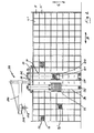
- honeycomb racks shown consist of a large number of shelf compartments 11, 11 ', 11 "... Arranged next to and above one another, into which pallets 12 containing goods 13, 13' ... are stored from the front 111 of the racks (arrow A '), after which the pallets 12 are then pulled out again in a drawer-like manner to remove stored goods 13, 13' ... for the compilation of the commissions called up (arrow A).
- the present invention addresses the handling of the pallets 12, that is to say in particular the removal of the pallets 12 from the rack for the removal of stored goods 13, 13 '... Contained in the pallets 12 for the compilation of material commissions called up.
- a gripper 21 which is movable relative to the rack and which is guided with the pallets 12 is provided along the rack (double arrow B) over the height of the rack (double arrow C) and in the loading and unloading direction (double arrow A / A ') can be brought into engagement, be it that he underpins the bottom side of the pallet 12 and engages in a recess on the bottom side of the pallet 12, be it that he engages under and behind an abutment on the front side of the pallet 12, and with which the Pallet 12 is pulled out of the shelf in the manner of a drawer or is completely removed from the shelf (arrow A) and then pushed back onto the shelf, that is to say in the compartment provided for it (arrow A ').
- the gripper 21 is arranged on a support 31 that can be moved in height on the support 31 on the support corridor 116 (double arrow B) and transversely (double arrow A / A ') to the shelf 31 (double arrow C), the support 31 the free end 321 of a cantilever 32 is underpinned, which in turn is displaceably or displaceably mounted in a carriage (double arrow B) 33 which is movable on the shelf along the front of the shelf (16, 16) in the sense of the double arrow A / A '.
- the support 31 which is provided on the corridor side with castors 311 designed as swivel rollers, is designed as a portal in which the gripper 21 guides itself with a slide 211 equipped with guide rollers 212.
- the gripper 21 is lifted by means of a winch 312 arranged above the head of the support 31.
- the actual gripper is formed by a bracket 213, starting from the guide carriage 211 and provided with cheeks 214 encasing the pallet 12, with a cam 216 projecting upwards at its free end.
- the respective shelf compartments 11, 11' ... are gripped by the gripper 21 with the support 31 moved against the shelf while leaving a free space by moving the shelf conveyor 31/32 / 33 approached along the shelf in alignment with the relevant shelf compartment and lifting the gripper 21 to the level of the free space below the shelf compartment.
- the gripper support 31 is then moved further against the shelf until the bracket 213 forming part of the gripper 21 extends into the shelf and in particular the gripper cam 216 has made a recess on the bottom side of the pallet 12 to be transferred into the material removal position.
- the gripper 21 is then raised to such an extent that the pallet 12 is slightly raised by the gripper console 213, the gripper cam 216 then also engaging with the pallet recess 112.
- the pallet 12 is then pulled out of the shelf in a drawer-like manner and thus transferred into the material removal position (FIG. 1).
- a work platform 22 is provided for the removal of material from the pallet 12 'in the material removal position, which is arranged on a support 36 which is supported by a roller 361 on the corridor 116, the support 36 in turn from the free end 371 of a further boom 37, which is assigned to the carriage 33 which can be moved on the shelf and is also displaceable in the sense of the double arrow A / A '.
- the pallet 12 'located in the removal position can be approached individually, so that material retrieved from the working platform 22 can be removed from the pallet 12' and placed, for example, on the console 221 provided on the working platform 22.
- the material removed from the pallet 12 'can then be lowered with the working platform 22 to the hallway 116 and transported there.
- a jib crane 39 To lift the material removed from the pallet 12 onto the corridor 116, there is also a jib crane 39 still installed on the carriage 33 with a trolley 392 that can be moved along the crane jib 391 and its associated winch 393. This jib crane 39 is then also provided for the storage of material in the pallets 12. The accessibility of the extended pallet 12 'for the jib crane 39 helps if the jib 33 acts on the gripper support 31 - as shown - off-center.
- the pallet 12 'no longer required is transferred from the removal position back to the shelf by moving the arm 32 in the direction of arrow A' and the associated movement of the gripper support 31 against the shelf.
- the gripper 21 and thus also the shelf conveyor 31/32/33 finally come out of engagement with the pallet 12 that has been re-stored.
- the shelf conveyor 31/32/33 is then ready to move to another pallet to be transferred into the material removal position 12 available.
- FIGS. 4 and 5 show a special embodiment of the new honeycomb rack system.
- a track-bound (16, 16) carriage 93 with an additional positive guidance 19, 19 is provided on the shelf along the front of the shelf in the sense of the double arrow B, in which a Boom 92 is slidably mounted in the sense of the double arrow A / A '.
- the gripper support 91 is arranged, which is supported on the corridor 116 via swivel castors 911.
- the auxiliary support 94 is arranged on a protrusion 931 of the carriage 93 projecting from the front of the shelf, which can be moved along the shelf by rails (18 '/ 941).
- the auxiliary support is also designed as a portal which can be passed through by the gripper 21 located on the gripper support 91 and in which there is a bridge 96 which undercuts the pallet 12 'which has been completely removed from the rack.
- the bridge 96 which lagging the level of the gripper bracket 213 and can be lowered prematurely from this level, can be lifted in the same direction as the gripper 21 by means of cable pulls 961 and 216 in connection with electric winches 962 and 217 with the gripper 21.
- the arm 92 can be displaced by means of a rack and pinion drive.
- the pallets 12 used in the new honeycomb racking system are equipped on the back with castors, by means of which they are supported on the brackets forming the shelf compartments on the shelf rails.
Landscapes
- Engineering & Computer Science (AREA)
- Mechanical Engineering (AREA)
- Warehouses Or Storage Devices (AREA)
Applications Claiming Priority (4)
| Application Number | Priority Date | Filing Date | Title |
|---|---|---|---|
| DE19823223594 DE3223594A1 (de) | 1982-06-24 | 1982-06-24 | Beschickungs- und entnahmevorrichtung fuer wabenregale |
| DE3223594 | 1982-06-24 | ||
| DE3237709 | 1982-10-12 | ||
| DE19823237709 DE3237709A1 (de) | 1982-10-12 | 1982-10-12 | Beschickungs-und entnahmevorrichtung fuer wabenregale |
Publications (2)
| Publication Number | Publication Date |
|---|---|
| EP0112348A1 EP0112348A1 (de) | 1984-07-04 |
| EP0112348B1 true EP0112348B1 (de) | 1986-08-27 |
Family
ID=25802597
Family Applications (1)
| Application Number | Title | Priority Date | Filing Date |
|---|---|---|---|
| EP83901907A Expired EP0112348B1 (de) | 1982-06-24 | 1983-06-24 | Wabenregalanlage, insbesondere beschickungs- und entnahmevorrichtung für eine solche anlage |
Country Status (8)
| Country | Link |
|---|---|
| EP (1) | EP0112348B1 (da) |
| CH (1) | CH663189A5 (da) |
| DE (1) | DE3365651D1 (da) |
| DK (1) | DK94984D0 (da) |
| GB (1) | GB2134092B (da) |
| NL (1) | NL8320192A (da) |
| SE (1) | SE449086B (da) |
| WO (1) | WO1984000142A1 (da) |
Family Cites Families (3)
| Publication number | Priority date | Publication date | Assignee | Title |
|---|---|---|---|---|
| FR1214242A (fr) * | 1957-10-16 | 1960-04-07 | Mécanisme pousseur, applicable notamment aux appareils de manutention mécaniques, tels que transporteurs élévateurs et appareils comportant ce mécanisme | |
| DE2102098A1 (de) * | 1971-01-16 | 1972-07-27 | Griese, Klaus P., 3001 Meilendorf | Stapel- und Kommisionierungsanlage für stabförmige Güter |
| US4063653A (en) * | 1976-10-05 | 1977-12-20 | Oehler, Wyhlen, Lagertechnic Ag | Automatic high shelf store |
-
1983
- 1983-06-24 DE DE8383901907T patent/DE3365651D1/de not_active Expired
- 1983-06-24 GB GB08404059A patent/GB2134092B/en not_active Expired
- 1983-06-24 WO PCT/DE1983/000114 patent/WO1984000142A1/de not_active Ceased
- 1983-06-24 NL NL8320192A patent/NL8320192A/nl unknown
- 1983-06-24 EP EP83901907A patent/EP0112348B1/de not_active Expired
- 1983-06-24 CH CH1405/84A patent/CH663189A5/de not_active IP Right Cessation
-
1984
- 1984-02-23 DK DK0949/84A patent/DK94984D0/da not_active Application Discontinuation
- 1984-02-23 SE SE8400999A patent/SE449086B/sv not_active IP Right Cessation
Also Published As
| Publication number | Publication date |
|---|---|
| SE8400999D0 (sv) | 1984-02-23 |
| GB2134092B (en) | 1986-12-31 |
| EP0112348A1 (de) | 1984-07-04 |
| WO1984000142A1 (fr) | 1984-01-19 |
| GB2134092A (en) | 1984-08-08 |
| GB8404059D0 (en) | 1984-03-21 |
| DK94984A (da) | 1984-02-23 |
| DE3365651D1 (en) | 1986-10-02 |
| NL8320192A (nl) | 1984-05-01 |
| DK94984D0 (da) | 1984-02-23 |
| SE8400999L (sv) | 1984-02-23 |
| SE449086B (sv) | 1987-04-06 |
| CH663189A5 (de) | 1987-11-30 |
Similar Documents
| Publication | Publication Date | Title |
|---|---|---|
| CH629442A5 (de) | Einrichtung zur speicherung von fuer die vorratshaltung dienenden paletten. | |
| DE102013009340A1 (de) | Einrichtung und Verfahren zum Ein- und Auslagern von stapelbaren Behältern | |
| DE102008022323A1 (de) | Shuttle-Kanallager, Shuttle-Bahnhof, Shuttle und Verfahren zum Betreiben des Shuttle-Kanallagers | |
| DE2509223B2 (de) | Lastübergabevorrichtung eines Regalförderzeuges | |
| DE2807002A1 (de) | Paletten-regallager | |
| WO2002018263A1 (de) | Vorrichtung zum befördern von personen mittels eines spreaders | |
| WO2003070607A1 (de) | Regalbediengerät mit einem lastaufnahmemittel | |
| EP3094576B1 (de) | System aus regaleinrichtung und korrespondierem teleskopierbarem lastaufnahmemittel ohne breitenverstellung | |
| DE4031883A1 (de) | Aufnahme- und abgabesystem fuer paletten und behaelter | |
| EP0213070B1 (de) | Lageranlage | |
| EP0242730B1 (de) | Regalanlage | |
| DE1556071A1 (de) | Mechanisiertes Palettenregallager | |
| DE3335289A1 (de) | Hochregalanlage | |
| DE2756385C2 (da) | ||
| EP0112348B1 (de) | Wabenregalanlage, insbesondere beschickungs- und entnahmevorrichtung für eine solche anlage | |
| DE102015115323A1 (de) | Regalbediengerät | |
| DE10241347B4 (de) | Lagereinrichtung zum Ein- und Auslagern von Behältern oder dergleichen in ein bzw. aus einem Regal | |
| EP1180491A1 (de) | Regalbediengerät | |
| DE3402996A1 (de) | Anlage zum ein- und auslagern von containern unter verwendung eines hochregallagers | |
| DE4425780C2 (de) | Verfahren und Einrichtung zum Entsorgen von Leerpaletten aus einem Regallager | |
| DE19813291B4 (de) | Lagermittel, vorzugsweise für lange Lagereinheiten | |
| EP0013033A1 (de) | Austragvorrichtung, insbesondere für das Austragen von Stabmaterial und dergleichen aus den Kassetten einer Regalanlage | |
| DE2914404A1 (de) | Regalbediengeraet | |
| DE4010905A1 (de) | Regalbediengeraet fuer ein stangenmaterial-lager | |
| DE2515429C3 (de) | Lastübergabevorrichtung eines Regalförderzeugs |
Legal Events
| Date | Code | Title | Description |
|---|---|---|---|
| PUAI | Public reference made under article 153(3) epc to a published international application that has entered the european phase |
Free format text: ORIGINAL CODE: 0009012 |
|
| AK | Designated contracting states |
Designated state(s): BE DE FR |
|
| 17P | Request for examination filed |
Effective date: 19840717 |
|
| GRAA | (expected) grant |
Free format text: ORIGINAL CODE: 0009210 |
|
| AK | Designated contracting states |
Kind code of ref document: B1 Designated state(s): BE DE FR |
|
| REF | Corresponds to: |
Ref document number: 3365651 Country of ref document: DE Date of ref document: 19861002 |
|
| RAP2 | Party data changed (patent owner data changed or rights of a patent transferred) |
Owner name: NEUHAEUSER, HELMUT, DIPL.-ING. |
|
| RIN2 | Information on inventor provided after grant (corrected) |
Free format text: THEOBALD, WOLFGANG |
|
| BECN | Be: change of holder's name |
Effective date: 19860827 |
|
| ET | Fr: translation filed | ||
| PLBE | No opposition filed within time limit |
Free format text: ORIGINAL CODE: 0009261 |
|
| STAA | Information on the status of an ep patent application or granted ep patent |
Free format text: STATUS: NO OPPOSITION FILED WITHIN TIME LIMIT |
|
| 26N | No opposition filed | ||
| PGFP | Annual fee paid to national office [announced via postgrant information from national office to epo] |
Ref country code: DE Payment date: 19920610 Year of fee payment: 10 |
|
| PGFP | Annual fee paid to national office [announced via postgrant information from national office to epo] |
Ref country code: FR Payment date: 19920629 Year of fee payment: 10 |
|
| PGFP | Annual fee paid to national office [announced via postgrant information from national office to epo] |
Ref country code: BE Payment date: 19920903 Year of fee payment: 10 |
|
| PG25 | Lapsed in a contracting state [announced via postgrant information from national office to epo] |
Ref country code: BE Effective date: 19930630 |
|
| BERE | Be: lapsed |
Owner name: NEUHAUSER HELMUT DIPL.-ING. Effective date: 19930630 |
|
| PG25 | Lapsed in a contracting state [announced via postgrant information from national office to epo] |
Ref country code: FR Effective date: 19940228 |
|
| PG25 | Lapsed in a contracting state [announced via postgrant information from national office to epo] |
Ref country code: DE Effective date: 19940301 |
|
| REG | Reference to a national code |
Ref country code: FR Ref legal event code: ST |